
20
Offshore wind turbine foundations – analysis and design
Abstract
Foundations for offshore wind farms involve significant technical challenges, including design requirements to withstand the harsh marine environment, prolonged impact under large wave loading and wind turbulence. These foundations are subjected to a combination of axial loads, low-amplitude cyclic lateral loads, bending and torsional moments generated by the offshore wind turbine (OWT) structure and various environmental factors. Monopiles are the most widely adopted foundation choice for OWT structures worldwide, in terms of ease of installation, economy and logistics. For monopiles, the applied loads and moments must be resisted by earth pressures mobilized in the surrounding soil, with an adequate factor of safety provided. Compared with the axial loading case, the cyclic lateral loads are considered governing for serviceability requirements. This chapter presents details on the environmental loading, geometric dimensions and geotechnical design considerations for OWT foundations, with a focus on monopile fondations. Existing methods for modelling soil under cyclic loading are reviewed, with emphasis on strain accumulation models that take into consideration the monopile–soil interaction. Inherent limitations and shortcomings of these models for the analysis/design of OWT monopile foundations are discussed, along with recommendations for future research needs.
Keywords
Cyclic; Foundation; Lateral load; Monopile; Offshore; Soil; Strain accumulation20.1. Foundation options for offshore wind-turbine structures
The economically viable development of wind-farms depends on efficient solutions being available for a number of technical issues, one aspect being the foundations. The foundation choice largely depends on water depth, seabed characteristics, applied loading, available construction technologies and, importantly, economic costs (Malhotra, 2010). Offshore wind turbine (OWT) structures may be found on gravity base, suction caisson, monopile, tripod or jacket/lattice foundations (collectively categorized as bottom-mounted structures) or using floating platforms tethered to the seabed (Fig. 20.1). The most widely adopted foundation choice in terms of its ease of installation, economy and logistics is the monopile, a single large-diameter hollow (pipe) pile; with an estimated 75% of all installed OWTs employing this solution (Blanco, 2009; Fischer, 2011; Malhotra, 2010). Hence, the focus of this chapter is on the geotechnical aspects of monopile foundations, with some discussion also provided on the other main foundation options.
Monopiles are typically used in shallow water depths (ie, 20–40 m), but may become too flexible for water depths of between ∼30 and 40 m, in which case monopiles fitted with guy wires, or alternatively tripod and jacket/lattice structures, are considered as economical alternatives. For greater depths, time-consuming installation and the effect of soil degradation, which occurs around the pile shaft at seabed level, make monopile foundation solutions prohibitive (Irvine et al., 2003). Tripods consist of a large-diameter central, steel tubular section that is supported over its lower length by three braces (Fig. 20.1(d)), which are connected to the seabed using different foundation types, including gravity base, suction bucket or piles. In this manner, the loads applied to the OWT and its support structure are mostly transferred axially (via the braces) to the seabed foundation. Complete installation of a tripod foundation system having, for example, a water surface to seabed length of up to 50 m typically takes two to three working days, often requiring special equipment for driving/drilling and working underwater (Esteban et al., 2011; Fischer, 2011). A jacket structure (see Fig. 20.1(e)) is a lattice frame comprising small-diameter steel struts that, similar to the tripod, is anchored to the seabed using different foundation types. Complete installation of the jacket structure generally takes up to 3 days. These structures are particularly suited for severe maritime weather conditions because of the additional structural stiffness and larger moment arm (across the seabed) for reacting against the bending loads, compared with monopile foundations. Jacket/lattice structures are also more adaptable to the conditions encountered onsite, increasing their application range, with geometrical variations of the substructure achieved relatively simply, but without altering the stiffness of the overall structure (De Vries, 2007). It is estimated that by 2020, 50–60% of OWTs will be supported by monopiles, with a further 35–40% supported by jacket and tripod systems (Babcock and Brown Company, 2012). The main reason for this shift is the attraction of jacket and tripod systems for deeper sea locations that provide consistently higher wind speeds and hence greater wind-energy production, which is a cube function of the wind speed (Tempel and Molenaar, 2002).

Figure 20.1 Support structure options showing typical ranges of water-depth application (adapted from Malhotra, 2010).
In the future, it is anticipated that floating structures, which are currently at the research and development stage, will be commercially used, particularly for water depths greater than 50 m (Saleem, 2011). Such floating platforms for wind turbines will impose many new design challenges. Among these, tension-leg platform concepts (Fig. 20.1(f)) are currently considered as more economical (Fischer, 2011) since the rigid body modes of the floater are limited to horizontal translation (surge and sway) and rotation around the vertical axis (yaw). For spare floater systems (Fig. 20.1(g)), buoyancy is provided to the wind turbine structure by a long slender cylinder/capsule that protrudes well below the water line (De Vries, 2007; Esteban et al., 2011; Fischer, 2011). For barrage floater systems, the wind turbine structure is placed on a barrage and attached, via anchor lines, to the seabed. The design of floating offshore wind turbines is discussed in chapter ‘Energy storage for offshore wind farms’.
20.2. System of loading on offshore foundations
Offshore foundations are subjected to a combination of loading, namely: axial (self weight) forces of the structure/machinery; repeating horizontal/lateral loads; bending and torsional moments. Apart from the self-weight forces, this system of loading is generated by environmental conditions and the operation of the machinery (Fig. 20.2). The foundations must be designed to resist large numbers of wind and hydrodynamic (ocean waves, current flow and tidal/swell action) load cycles of varying direction, amplitude and frequency occurring at the proposed site over the project's lifetime of typically 25 years or more (Sahin, 2004). Another variable/cyclic load acting on OWT structures, depending on the geographic setting, is from ice sheets. Seismic loading is considered as a special type of dynamic loading. However, the focus of this chapter is on wind and wave loading since these are considered more important in the assessment of the OWT structure's fatigue life.

The wave loading (forces) acting on OWT structures is often greater than the wind loading. However, in terms of the overturning (bending) moments generated, the wave loading generally has only a minor role, compared with the rotor–thrust reaction to the wind loads. This occurs due to the smaller lever arm for the bending moment generated by the wave loading, as compared with the overall tower length, and longer lever arm of the rotor thrust in considering the overall overturning moment acting on the foundation system (LeBlance, 2009). For instance, for OWT monopiles installed in the North Sea, Byrne and Houlsby (2003) reported that the rotor thrust reaction contributed to approximately 25% of the total horizontal load, but generated approximately 75% of the total overturning moment. The density of the medium must also be considered when comparing wind and wave loading, with the density of sea water significantly greater than that of air. Hydrodynamic loads generally only become significant for greater water depths and (or) wave heights, which cause the lever arm of the wave load to increase, along with the intensity of the lateral load generated by the water (Fischer, 2011). Fluctuations in wind speed about a mean value impose repeated aerodynamic loads, although when considering the dynamic behaviour of offshore structures, this cyclic nature is generally insignificant compared with the repeated wave loads (Journée and Massie, 2001). Dynamic analysis of offshore structures that takes into account the fluctuating wind load is necessary in cases where the wind field contains energy at frequencies near the offshore structure's natural frequency, although for monopile foundations, the difference between these frequencies is usually high. When the loading frequency gets closer to the structure's natural frequency of vibration (API, 2010), the repeating load can be termed dynamic load. This tends to excite the structure dynamically, leading to resonance and the development of higher stresses in the support structure and foundation, but more significantly to a higher range of stresses; an unfavourable situation in considering fatigue life. A correct evaluation of the total hydrodynamic load acting on an offshore structure must consider the combined current flow and wave particle velocities. Morison et al. (1950) formulated an equation to predict the wave loads acting on a vertical pile exposed to horizontal sinusoidal oscillatory flow. In their equation, the linear inertial force and adapted quadratic drag force (from real flows and constant currents) are superimposed to obtain the resultant force acting on the projected area of the pile. Morison's formula is strictly limited for use with slender structural elements, characterized by D/λ < 0.2, where D is the diameter of the structural element between seabed level and the transition piece, and λ is the impinging wavelength of the ocean wave. For larger offshore structures (eg, gravity foundations and OWT monopiles), the wave field is significantly influenced and a diffraction regime emerges. Potential flow theory is more suitable for the calculation of wave loads on such structures (Batchelor, 1967). However, a significant number of existing offshore structure designs have employed Morison's equation even though the criterion of D/λ < 0.2 may not have been fully satisfied (Haritos, 2007).
For geotechnical design, the relative proportions and importance of the different types of loads applied essentially depend upon the kind of foundation system being considered. For gravity base foundations, potential failure modes are in bearing capacity or excessive settlement; hence the vertical (self-weight) loads are generally the major design consideration (Malhotra, 2010). For monopile foundations, the lateral deflection (rotation) response of the monopile largely controls the serviceability limit state of the whole structure. Hence, lateral loads and resulting moments are more critical compared with the vertical loads for monopile foundations. In other words, the monopile's response under repeated lateral loading is the major design consideration, with the monopile design dominated by considerations of its dynamic and fatigue responses under working loads, rather than its ultimate load-carrying capacity. For instance, existing OWTs have rotor diameters ranging between ∼90 and 120 m (power-generation capacities of 3–6 MW (Tong, 2010)) and produce gravitational loading in the range of ∼2–8 MN. For instance, Byrne and Houlsby (2003) reported vertical loading of 6 MN acting on the monopile foundation for an anticipated 3.5 MW OWT located in the North Sea, with lateral loading from wind and wave factors accounting for up to 66% of the vertical loading. The precise magnitude of these loads will vary with the size of the installation, the detailed design, and local environmental conditions. This scenario is more onerous when the repeating lateral loading occurs at varying frequency, load amplitude and direction (Arshad and O'Kelly, 2013). At some critical level of load amplitude and (or) frequency, the repeating lateral loads can cause significant reductions in the lateral soil resistance for a monopile foundation (Ramakrishna and Rao, 1999).
20.3. General aspects of OWT monopile foundation system
Monopiles with outer diameters of 4–6 m have been successfully installed, with embedment (penetration) depths of between 20 and 40 m, depending upon the wind-power generation capacity of the OWT (Peng et al., 2006; Achmus et al., 2009; LeBlanc et al., 2010; Peng et al., 2010; Cuéllar et al., 2012; Pappusetty and Pando, 2013). These monopiles are manufactured from steel tubular sections with wall thicknesses (depending on installation and loading conditions) ranging from 55 to 150 mm (Haiderali et al., 2013), but more frequently 60–80 mm, and have an overall mass of up to 1000 tonnes. Depending on soil conditions, monopiles are typically installed in the seabed using largeimpact hammers, by vibratory pile driving (vibropiling), prebored piling, or drill/driving techniques (Malhotra, 2010; Igoe et al., 2013a). Noise-mitigation measures, including bubble curtains, isolation casings (pile sleeve), dewatered cofferdams, and hydro sound dampers, are employed during pile driving in order to limit emissions to environmentally friendly levels (Saleem, 2011; OSPAR Commision, 2014). Complete installation of the monopile is usually achieved within 24 h (Junginger et al., 2004; Fischer, 2011; Saleem, 2011). The transition piece of the OWT structure provides a means of correcting vertical imprecisions of the monopile that may have arisen during its installation. The transition piece, which has a slightly larger (or smaller) diameter than the monopile, is grouted to the monopile, with an overlap. Mechanical shear connectors increase the reliability of this connection and alleviate the effect of long-term grout shrinkage on the connection capacity. New design features include grouted conical-shaped connections and shear keys (DNV, 2011). In some instances, the installed monopile can extend above the water surface, connecting directly to the tower.
The monopile diameter and embedment length are primarily dependent on the OWT's power-generation capacity (an indirect measure of the applied loading), seabed characteristics/soil properties and severity of environmental loading. OWT monopiles invariably have slenderness (in terms of embedment length to diameter) ratio values of less than 10 (typically ranging from 5 to 6), and the embedded portion of the monopile is therefore considered to behave as a ‘rigid’ structure, for which rotation is prominent over bending (Tomlinson, 2001; Peng et al., 2011). In other words, the surrounding soil would fail in bearing capacity rather than the monopile failing over its embedded length by plastic hinges; ie, its structural behaviour under lateral loading is defined by its rotation as a rigid body. The embedment length must be sufficient for the monopile to meet design criteria, including vertical stability and limiting horizontal deflection/rotation over its design life. Limiting the rotation is more important for ‘rigid’ monopiles. As a general rule, under field loading, rotation of the monopile by up to 0.5 degree from its vertical alignment (Achmus et al., 2009; LeBlanc, 2009; LeBlanc et al., 2010; DNV, 2011) or lateral deflections occurring at seabed level of up to 120 mm (based on practical experience) (Malhotra, 2010) are considered as limiting values for the proper operation of the wind turbine. Transport of sediment from beneath the scour protection (typically rock/stone layers) zone around OWT monopiles may cause sinking of the scour protection, particularly for piles founded in sandy soil deposits. This alters the natural frequency of the dynamic response in an unfavourable manner (van der Tempel et al., 2004).
For a typical 5-MW OWT installed in the North Sea, a hub height of ∼95 m above mean sea level and rotor diameter of 125 m would produce the approximate quasi-static loading scenario (acting at the seabed level) given in Table 20.1. This example scenario demonstrates that for the monopile foundation, horizontal loading from wind and wave causes extremely high bending moments (resisted in lateral compression of the surrounding soil) and principally controls the foundation design. To ensure the monopile is torsionally stable, sufficient circumferential shear resistance must be mobilized at the pile–soil interface, although the torsional moment to be resisted is usually small (Table 20.1). Further, the connections between the tower and transition piece and between the transition piece and monopile foundation must be capable of transferring these bending and torsional moments, with adequate factors of safety.
Table 20.1
Loading at seabed level for monopile supporting 5-MW OWT (Lesny and Wiemann, 2005)
| Axial load | 35 MN |
| Horizontal load | 16 MN |
| Bending moment | 562 MN m |
| Torsional moment | 4 MN m |
20.4. Offshore design codes and methods
At present, current practice for the analysis, design and installation of OWT monopiles usually relies on general geotechnical standards which are complemented by more specific guidelines and semiempirical formulae developed mainly by the offshore oil/gas industries (American Petroleum Institute (API), 2010; DIN, 2005; Det Norske Veritas (DNV), 2011). However, large-diameter monopile foundations for current and future OWT structures are well outside the scope of current experience and analysis/design methods, including the API (2010) and DNV (2011) recommended practices, which are largely based on limited field data obtained for relatively small-diameter (ie, flexible) piles under low numbers of load cycles. For these standards, wave loading is of primary concern when extrapolating to predict extreme events. However, designers of OWT structures must consider wave and wind load spectra simultaneously (IEC, 2005). Hence, careful consideration of these differences in applied loading, as well as other inherent limitations underlying semi-empirical offshore oil/gas industry formulae, is required in extrapolation of these formulations for the design of OWT monopile foundations. Often these formulations cannot be applied with confidence by the offshore wind-power industry to achieve optimum results and economy (Dobry et al., 1982).
Current design standards and guidelines on the serviceability of piles under cyclic lateral loading are limited. Over its service life, a typical 2-MW OWT structure is subjected to ∼100 cycles of 2.0-MN magnitude and 107 cycles of 1.4-MN magnitude in lateral loading, which correspond to the serviceability limit state and fatigue limit state, respectively (GL, 2005). Factors affecting the cyclic response include the diameter and wall thickness of the monopile, its free spanning and embedded lengths, the soil properties, soil–pile relative stiffness, the characteristics of the applied loading and the pile installation method (Malhotra, 2010).
20.5. Investigation of monopile–soil behaviour
20.5.1. Soil behaviour and testing
Apart from very small strain levels of <10−3 strain (Atkinson and Sallfors, 1991; O'Kelly and Naughton, 2008), the stress–strain relationship for soil is invariably highly non-linear (inelastic), with the strength and stiffness properties often strongly dependent on the stress history and stress path followed under loading. Seabed/sedimentary deposits are typically cross-anisotropic (O'Kelly, 2006). Due to the initial and stress-induced anisotropy (Naughton and O'Kelly, 2004), soil deformations can occur within the influence zone of the embedded monopile whenever changes occur in the magnitudes of the three principal stresses acting on a soil element and (or) the orientations of the principal stress axes on account of the applied cyclic lateral loading. In this regard, an analogy may be drawn between the soil behaviour in the immediate vicinity of the OWT monopile's shaft and that beneath a highway pavement under repeated wheel loading of varying intensity. For both scenarios, changes in the magnitudes and the directions of the principal stresses acting on a soil element occur simultaneously during each load cycle.
The values of pertinent parameters used to describe the soil response under cyclic loading are often determined using cyclic triaxial tests (Das, 2008), although the axisymmetric system of cyclic axial loading and all around confinement pressure acting on the test-specimen is usually not compatible with the generalized stress conditions encountered in situ. An advancement on cyclic triaxial testing is provided by the hollow cylinder apparatus (HCA) (O'Kelly and Naughton, 2005, 2009), which allows independent control of the magnitudes of the three principal stresses, as well as the orientation of the major–minor principal stress axis. The HCA is ideally suited for simulating cyclic multidirectional loading conditions on cross-anisotropic test specimens. Generalized stress-path testing can be performed to simulate the stress history and in-service loading conditions at specific locations in the soil foundation (Naughton and O'Kelly, 2005; O'Kelly and Naughton, 2009). In many practical situations, laboratory testing may become too laborious, expensive and time-consuming. In situ testing techniques, including the Cone Penetration Test method (Doherty et al., 2012; Igoe et al., 2013b), can be used for offshore site investigations and afford another approach in the determination of pertinent design parameter values.
20.5.2. Physical testing of monopile installations
Compared with the single one-off structure typically used by the offshore oil and gas industries, the strategy of predictions and in situ measurement of the behaviour for every OWT foundation in a wind farm project is often technically laborious, economically unrealisable and hence not practicable. Full-scale pile tests are expensive and time-consuming to perform. In this case, an economical design procedure can be efficiently and confidently applied provided experimental verifications are achievable to understand the monopile–soil behaviour through model studies. For instance, El Naggar and Wei (1999), Dührkop (2009), LeBlanc et al. (2010), Peng et al. (2011) and Arshad and O'Kelly (2014) have reported investigations of scaled model monopiles subjected to many thousands of lateral load cycles in order to validate numerical predictions and design rules. For example, the apparatus developed by Arshad and O'Kelly (2014) allows the investigation of the effects of lateral loading direction, amplitude, frequency and waveform shape on the response of a model monopile at 1 g. Scaling laws (Lai, 1989; Muir Wood et al., 2002; LeBlanc et al., 2010; Bhattacharya et al., 2011; Cuéllar et al., 2012) preserve constitutive and kinematic similarities between the prototype and model such that the test results can be directly applied, once the soil at site is the same as that used for the scaled tests. The best way is to link the model tests with element test parameters (Lombardi et al., 2013).
20.5.3. Strain accumulation models
20.5.3.1. Models for long-term cyclic lateral loading
The strain accumulation in a soil element under repeated loading is dependent on its engineering properties, the stress path/level and the number of load cycles (Niemunis et al., 2005; Karg, 2007). Many methods with different complexity and levels of acceptability have been developed to predict the strain accumulation in a soil element subjected to large numbers of load cycles. However, a major limitation to their application for offshore foundation design calculations is that only a few (listed in Table 20.2) consider simulation of the monopile–soil foundation interaction under cyclic lateral loading. Considerable differences of opinion exist regarding the rate of cyclic strain accumulation; for instance, power function (Little and Briaud, 1988) and logarithmic trend (Lin and Liao, 1999) relationships have been proposed. The most popular of these, and the method recommended in offshore design codes, including the API (2010) and DNV (2011), is based on the Winkler model (ie, pile acts as a beam supported by a series of uncoupled non-linear elastic springs which represent the soil reaction) and is commonly referred to as the p–y method.
20.5.3.2. The p–y method
In general terms, a p–y curve is typically obtained by plotting the lateral soil resistance (p) response against the lateral deflection (y) of the pile, arising from the action of a horizontal load (H) applied at the pile head (Fig. 20.3). Fig. 20.3(b) shows the lateral soil resistance generated around the pile circumference at a particular depth (xt) and the corresponding pile deflection (yt) response. The effects of soil stratification, non-linearity and other soil properties are automatically taken into account by determining p–y curves specific to different depth ranges along the pile embedment length (Fig. 20.3(c)). For instance, soil stiffness typically increases with depth, which is reflected by increasing values of the spring stiffness (Epy), defined as the secant modulus of the p–y curve. The pile deflection that develops under given loading conditions and constraints can be predicted by implementing the related p–y curve in a simple non-dimensional framework (eg, using the approach after Randolph (1981)), or in numerical methods using computer software such as COM624P (Wang and Reese, 1993).
Table 20.2
Strain accumulation models that consider pile–soil interaction
Little and Briaud (1988). See also Kuo et al. (2012), numerical studies; Peralta and Achmus (2010), model studies in medium-dense sand
Lin and Liao (1999). See also Verdure et al. (2003) and Li et al. (2010), centrifuge tests on miniature piles in sand
High cycle accumulation method. See Niemunis et al. (2005), finite-element calculations using ABAQUS; Wichtmann et al. (2010)

Figure 20.3 p–y method of analysis for laterally loaded pile. Note: Epy, spring stiffness; H, horizontal/lateral load; M, bending moment; V, axial load. (a) Deflected shape of monopile (vertical section). (b) Soil resistance pt exerted due to pile deflection yt for a specific depth xt (horizontal section). (c) Winkler model approach with changing shape of p–y curves against depth.
20.5.3.3. Limitations of design approaches based on p–y method
Current pile design methodology based on p–y curves, as described in API (2010) and DNV (2011) recommended practice, has gained broad recognition on account of the low failure rate for piles in service over many decades. However, some caution is necessary in applying this methodology to the design of OWT monopiles since the approach may then be applied outside of its verified range. Further, several important design issues may not be properly taken into account. Firstly, these standards (codes) rely on methods built upon limited empirical data obtained for long (flexible) piles, for which bending is significant. In contrast, existing and planned OWT monopile foundations, having slenderness ratio values of less than 10, exhibit rigid pile behaviour (Achmus et al., 2009; Peng et al., 2011). Secondly, pile rotation (rather than deflection) is generally more prominent for OWT foundations, with the rotation occurring about a point located approximately one diameter above the pile base. Thirdly, the p–y curves for cyclic loading presented in API (2010) and DNV (2011) were primarily formulated for the evaluation of the ultimate lateral load-carrying capacity mobilized under relatively few load cycles (<200). In contrast, OWT structures experience many millions of low-amplitude cycles over their service life. These points cast doubt on the appropriateness of API (2010) and DNV (2011) recommended practice (based on p–y curves) in predicting the in-service behaviour of OWT monopiles. Fourthly, despite the p–y stiffness parameter Epy being a pile–soil interaction parameter, these standards only consider the soil properties in formulating the p–y curves. The influence of the pile properties on the mobilized p–y curves remains an open question. Fifthly, these standards always predict a degradation of the absolute secant stiffness for monopiles in sandy soil, irrespective of the density state or number of lateral load cycles. Model studies on monopiles in loose (LeBlanc et al., 2010; Bhattacharya et al., 2011) and dense (Cuéllar et al., 2012; Rosquoet et al., 2007) sands suggest that the foundation stiffness (cyclic) increases with the number of load cycles due to densification of the soil next to the pile (LeBlanc, 2009; Bhattacharya and Adhikari, 2011; Cuéllar et al., 2012). Furthermore, the API (2010) and DNV (2011) approaches do not provide a means of calculating the accumulated pile deflection (rotation) occurring during cyclic loading, rather they only suggest an empirical factor for this purpose.
20.6. Design of OWT foundation
20.6.1. Resonance in structural system
The basic driving motive for the design is to avoid the occurrence of resonance in the dynamic behaviour of the structural system under in-service loading. The OWT structure is considered too flexible if its natural frequency falls within the ‘soft–soft’ zone (region before the first excitation (‘1P’) frequency range of typically 0.17–0.33Hz) and too rigid, heavy and expensive if its natural frequency falls within the ‘stiff–stiff’ zone (region after the blade-passing frequency range (‘3P’) of typically 0.5–1.0 Hz for three-bladed turbines). Another important reason for avoiding the ‘soft–soft’ frequency region is that wind turbulence and wave excitation frequencies usually fall within this zone (LeBlance, 2009). For OWT structures, this invariably leads to the development of higher stresses in the support structure and its foundation, which is an unfavourable situation in considering fatigue life. Hence, it is important to ensure that excitation frequencies with high energy levels do not coincide with the natural frequency of the support structure and its foundation. In this regard, DNV (2011) suggests that the natural frequency should not come close to the 1P or 3P frequency ranges, with the ‘wanted frequency’ region (referred to as the ‘soft–stiff’ zone) remaining away from the 1P and 3P ranges by a margin of at least 10%. Note that scour alters the natural frequency of the dynamic response in an unfavourable manner, particularly for OWT monopiles installed in sandy soil. The maximum scour depth depends on the monopile diameter, flow Froude number, and soil characteristics (van der Tempel et al., 2004). A detailed insight into the dynamic of the soil–structure behaviour for offshore applications is given by Adhikari and Bhattacharya (2011, 2012), Bhattacharya et al. (2011, 2013), Bhattacharya and Adhikari (2011) and Lombardi et al. (2013).
For OWT monopiles, ‘soft–stiff’ design necessitates high structural and dynamic stiffness, which can be achieved by increasing the monopile diameter, or less efficiently by increasing the pile wall thickness. However, larger-diameter monopiles introduce drawbacks (Schaumann and Böker, 2005), including greater wave loading and larger equipment necessary for their installation, thereby leading to an increase in the initial capital cost of the project. Compared with monopiles, the lattice frame of jacket support structures (Fig. 20.1(e)) provides large bending stiffness and a more favourable mass-to-stiffness ratio, resulting in relatively high bending Eigen-frequencies and reduced hydrodynamic excitation (De Vries et al., 2011). However, the torsional stiffness is reduced, potentially leading to dynamic problems. Further, the fabrication of a jacket structure is complex, difficult to automate and resource-intensive, with its installation generally requiring up to 3 days, compared to within typically 24 h for a monopile foundation. These factors tend to make jacket structures costly. They are designed as either ‘soft–stiff’ or ‘stiff–stiff’ systems, with the requirement to avoid resonance with the 3P frequency range, especially for ‘soft–stiff’ systems (Fischer, 2011). For tripods, bracing along the lower length of the central tubular section (reduces bending-moment loading) increases overall bending stiffness (Schaumann and Böker, 2005; Saleem, 2011), with typical Eigen-frequency values ranging between those for the monopile (at the lower end of this range) and jacket support structures, considering similar rotor–nacelle configurations and environmental conditions.
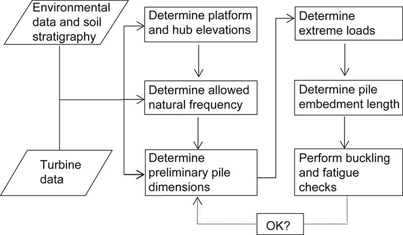
20.6.2. Design procedure
An iterative procedure is usually adopted in the design, with the basic steps involved for an OWT monopile foundation system set out in Fig. 20.4. Data on the environmental conditions, wind turbine and soil stratigraphy are required. The environmental data are used to determine the required platform and hub elevations for the OWT structure and to select initial/trial dimensions for the monopile foundation, leading to the determination of the natural frequency of the whole structural system. Checks on resonance frequency are applied, along with predictions of the anticipated rotation/deflection and settlement responses of the proposed monopile over its design life. The applied loads and moments are estimated for the initial/trial dimensions of the OWT structure considering its associated wind turbine and environmental data. For instance, the RECAL software, a MATLAB tool for offshore wind turbine modelling developed by Cerda Salzmann (2004), can be used to estimate the horizontal (shear) force and bending moment acting (at seabed level) on the monopile, as documented by De Vries and van der Tempel (2007). RECAL can simulate both wind and wave time-series, from which it calculates the loads acting on the support structure (including monopile), as well as its dynamic behaviour. For monopile foundations, torsional moments are usually only a small fraction of the bending moment (Lensy and Wiemann, 2005); eg, see typical loading values listed in Table 20.1 for a 5-MW wind turbine. Hence, provided the checks on lateral forces and bending moments are satisfied, torsional moments are generally not critical. Fatigue and buckling checks are performed at a more advanced stage in the design process. A discussion on numerical modelling, considering dynamic soil constitutive models, torsional loading and damping-related issues, is beyond the scope of this chapter. Details on these topics can be found in Basack and Dey (2012), Basack and Sen (2014), Guo (2006, 2013) and Rani and Prashant (2015).
20.6.3. Monopile embedment length and foundation stability
The monopile embedment length must be sufficient to ensure vertical and lateral stability. Studying the interaction effects for piles under combined axial and lateral loading would no doubt call for a systematic and sophisticated analysis, although the pertinent literature is very limited. Numerical analysis by Karthigeyan et al. (2007) indicates that for sandy soils, the presence of axial loads increases the pile's lateral load-carrying capacity by as much as 40% (depending on the magnitude of axial loading), but causes marginal reductions for clayey soils. According to current practice (Karthigeyan et al., 2006; Moayed et al., 2012; Rahim and Stevens, 2013), for monopile design, separate analyses are performed that consider (i) the axial loading only, to determine the bearing capacity and settlement response, and (ii) the lateral loading only, to determine its ultimate lateral load-carrying capacity and flexural behaviour through cantilever action. The input data for the monopile design include soil strength and stiffness profiles against depth, pile characteristics (its cross-sectional dimensions and properties, material strength and stiffness), and the design loads and moments (De Vries, 2007; Jaimes, 2010; Tong, 2010).
20.6.3.1. Axial pile stability
The ultimate axial load-carrying capacity (under static loading) (Qd) of the monopile can be determined using Eq. [20.1], which is the recommended practice by API (2010), and has been employed by many researchers; eg, De Vries (2007), Igoe et al. (2010), Haiderali et al. (2013) and Bisoi and Haldar (2014).
![]() [20.1]
[20.1]
where Qf is the shaft friction capacity, Qb is the end-bearing capacity, f is the unit skin friction, A is the shaft area pertaining to the embedded monopile length, q is the unit end-bearing capacity, and Ab is the base area of the monopile.
For monopiles with a diameter of 4 m or greater, the pile plug resistance is usually not taken into account (van der Tempel, 2006). Further, it has been shown that degradation of the shaft friction capacity due to cyclic axial loading (Gavin and O'Kelly, 2007; Igoe et al., 2011) can lead to accumulating displacements and may ultimately cause a severe reduction in the axial load-carrying capacity. Consideration of this degradation of shaft friction in the design process is still an open question. However, no reduction in the axial load-carrying capacity is to be expected if a certain magnitude of cyclic load amplitude is not exceeded; for further details, see Poulos (1988) and Abdel-Rahman and Achmus (2011). Numerous design charts available in the literature make it possible to distinguish between stable and unstable loading levels to ensure a design solution on the safe side.
20.6.3.2. Lateral pile stability
In current practice, the ultimate lateral load-carrying capacity of the monopile is determined using the conventional p–y curves (API, 2010; DNV, 2011), which are dependent on the soil type and loading conditions. For serviceability, compared with the axial loading case, the cyclic lateral loads are considered governing, as described in several design codes (eg, API (2010); DNV (2011)) and documented by many researchers (Achmus, 2010; Leblanc et al., 2010; Malhotra, 2010; Peng et al., 2011; Bhattacharya et al., 2013; Kuo et al., 2012; Zhu et al., 2013; Haiderali et al., 2013; Lombardi et al., 2013; Nicolai and Ibsen, 2014; Carswell et al., 2015). Hence, the pile size and embedment length necessary to satisfy the lateral load requirements are generally greater than those necessary for axial loading (Kopp, 2010). For OWT foundations, the monopile must mobilise sufficient soil resistance over its embedded length to transfer all the different types of applied loads to the surrounding soil, with adequate safety margins provided, and also to prevent toe ‘kick’ (displacement at the pile base and excessive lateral deflection/rotation of the pile from occurring. Checks on the values of lateral deflection (occurring at seabed level) and rotation of the monopile are applied and its embedment length optimized accordingly. The lateral deflection and rotation anticipated for the design loads are calculated by considering the closed-form solutions proposed, for example, by Randolph (1981), Broms (1964) or Matlock and Reese (1960). These methods are related to monotonic (static) loading conditions and hence there is no consideration of the number of lateral load cycles.
20.7. Future outlook and research needs
Reductions in the levelized cost of energy and projected increases in the design life of OWT projects can be achieved, in part, by developing and implementing improved design codes for the OWT support structures and foundations (as well as for the wind turbines themselves), along with the use of innovative materials in their fabrication. Sources, types and methods of analyses for the determination of the magnitudes of the environmental loads and moments exerted on OWT foundations, including for long-term and extreme conditions, are well documented in the literature. However, the design of large-diameter (rigid) monopile foundations for OWT structures is well outside the scope of current experience and analysis/design methods (including API (2010) and DNV (2011) recommended practice), which are mainly based on experimental data obtained for smaller-diameter (flexible) piles that were subjected to low numbers of load cycles (<200). Further, the response of OWT monopiles to in-service cyclic (dynamic) loading scenarios and their long-term low-amplitude cyclic lateral-load behaviour are not well documented/understood. There are also conflicting views among researchers regarding the severity of lateral strain accumulation for monopiles under different loading scenarios. The scarcity of field data reported in the literature for cyclic lateral loading of large-diameter monopiles makes the validation of current and improved design methods, and also the calibration of numerical models for offshore monopiles, difficult. In-depth experimental and numerical studies are necessary to bridge the knowledge gap between the existing design codes/guidelines (primarily developed for the offshore oil/gas industries) and the more onerous loading conditions and larger monopile foundations required for OWTs. Instrumented field testing of full-scale monopiles (having comparable size (slenderness ratio) to that of current and proposed OWT monopile foundations), with the application of high numbers of lateral load cycles (>106), combined with more extensive programmes of testing on reduced-scale piles for different soil conditions, is warranted. Such studies would provide valuable information for the validation of current and improved methods/theories for the analysis and design of OWT monopiles, as well as for the calibration of numerical models.
Nomenclature
| Ab | Base area of pile |
| A | Shaft area pertaining to embedded pile length |
| D | Diameter of structural element between seabed level and transition piece |
| Epy | Soil stiffness (secant modulus of p–y curve) |
| f | Unit skin friction of pile |
| H | Horizontal load applied at pile head |
| M | Bending moment |
| p | Lateral soil resistance |
| pt | Lateral soil resistance exerted due to pile lateral deflection yt |
| q | Unit end-bearing capacity of pile |
| Qd | Ultimate static axial load-carrying capacity of pile |
| Qf | Shaft friction capacity |
| Qb | End-bearing capacity |
| V | Axial load applied at pile head |
| y | Lateral deflection of pile |
| yt | Lateral deflection of pile for specific soil depth xt |
| λ | Impinging wavelength of ocean wave |
Abbreviations
| API | American Petroleum Institute |
| DIN | Deutsches Institut für Normung |
| DNV | Det Norske Veritas |
| HCA | Hollow cylinder apparatus |
| OWT | Offshore wind turbine |
| 1P | First excitation frequency range |
| 3P | Blade-passing frequency range for three-bladed turbine |
..................Content has been hidden....................
You can't read the all page of ebook, please click here login for view all page.