
Chapter 1. Introduction to OpenGL ES 3.0
OpenGL for Embedded Systems (OpenGL ES) is an application programming interface (API) for advanced 3D graphics targeted at handheld and embedded devices. OpenGL ES is the dominant graphics API in today’s smartphones and has even extended its reach onto the desktop. The list of platforms supporting OpenGL ES includes iOS, Android, BlackBerry, bada, Linux, and Windows. OpenGL ES also underpins WebGL, a web standard for browser-based 3D graphics.
Since the release of the iPhone 3GS in June 2009 and Android 2.0 in March 2010, OpenGL ES 2.0 has been supported on iOS and Android devices. The first edition of this book covered OpenGL ES 2.0 in detail. The current edition focuses on OpenGL ES 3.0, the next revision of OpenGL ES. It is almost inevitable that every handheld platform that continues to evolve will support OpenGL ES 3.0. Indeed, OpenGL ES 3.0 is already supported on devices using Android 4.3+ and on the iPhone 5s with iOS7. OpenGL ES 3.0 is backward compatible with OpenGL ES 2.0, meaning that applications written for OpenGL ES 2.0 will continue to work with OpenGL ES 3.0.
OpenGL ES is one of a set of APIs created by the Khronos Group. The Khronos Group, founded in January 2000, is a member-funded industry consortium that is focused on the creation of open standard and royalty-free APIs. The Khronos Group also manages OpenGL, a cross-platform standard 3D API for desktop systems running Linux, various flavors of UNIX, Mac OS X, and Microsoft Windows. It is a widely accepted standard 3D API that has seen significant real-world usage.
Due to the widespread adoption of OpenGL as a 3D API, it made sense to start with the desktop OpenGL API in developing an open standard 3D API for handheld and embedded devices and then modify it to meet the needs and constraints of the handheld and embedded device space. In the earlier versions of OpenGL ES (1.0, 1.1, and 2.0), the device constraints that were considered in the design included limited processing capabilities and memory availability, low memory bandwidth, and sensitivity to power consumption. The working group used the following criteria in the definition of the OpenGL ES specification(s):
• The OpenGL API is very large and complex, and the goal of the OpenGL ES working group was to create an API suitable for constrained devices. To achieve this goal, the working group removed any redundancy from the OpenGL API. In any case where the same operation could be performed in more than one way, the most useful method was taken and the redundant techniques were removed. A good example of this is seen with specifying geometry, where in OpenGL an application can use immediate mode, display lists, or vertex arrays. In OpenGL ES, only vertex arrays exist; immediate mode and display lists were removed.
• Removing redundancy was an important goal, but maintaining compatibility with OpenGL was also important. As much as possible, OpenGL ES was designed so that applications written to the embedded subset of functionality in OpenGL would also run on OpenGL ES. This was an important goal because it allows developers to leverage both APIs and to develop applications and tools that use the common subset of functionality.
• New features were introduced to address specific constraints of handheld and embedded devices. For example, to reduce the power consumption and increase the performance of shaders, precision qualifiers were introduced to the shading language.
• The designers of OpenGL ES aimed to ensure a minimum set of features for image quality. In early handheld devices, the screen sizes were limited, making it essential that the quality of the pixels drawn on the screen was as good as possible.
• The OpenGL ES working group wanted to ensure that any OpenGL ES implementation would meet certain acceptable and agreed-on standards for image quality, correctness, and robustness. This was achieved by developing appropriate conformance tests that an OpenGL ES implementation must pass to be considered compliant.
Khronos has released four OpenGL ES specifications so far: OpenGL ES 1.0 and ES 1.1 (referred to jointly as OpenGL ES 1.x in this book), OpenGL ES 2.0, and OpenGL ES 3.0. The OpenGL ES 1.0 and 1.1 specifications implement a fixed function pipeline and are derived from the OpenGL 1.3 and 1.5 specifications, respectively.
The OpenGL ES 2.0 specification implements a programmable graphics pipeline and is derived from the OpenGL 2.0 specification. Being derived from a revision of the OpenGL specification means that the corresponding OpenGL specification was used as the baseline for determining the feature set included in the particular revision of OpenGL ES.
OpenGL ES 3.0 is the next step in the evolution of handheld graphics and is derived from the OpenGL 3.3 specification. While OpenGL ES 2.0 was successful in bringing capabilities similar to DirectX9 and the Microsoft Xbox 360 to handheld devices, graphics capabilities have continued to evolve on desktop GPUs. Significant features that enable techniques such as shadow mapping, volume rendering, GPU-based particle animation, geometry instancing, texture compression, and gamma correction were missing from OpenGL ES 2.0. OpenGL ES 3.0 brings these features to handheld devices, while continuing the philosophy of adapting to the constraints of embedded systems.
Of course, some of the constraints that were taken into consideration while designing previous versions of OpenGL ES are no longer relevant today. For example, handheld devices now feature large screen sizes (some offer a higher resolution than most desktop PC monitors). Additionally, many handheld devices now feature high-performance multicore CPUs and large amounts of memory. The focus for the Khronos Group in developing OpenGL ES 3.0 shifted toward appropriate market timing of features relevant to handheld applications rather than addressing the limited capabilities of devices.
The following sections introduce the OpenGL ES 3.0 pipeline.
OpenGL ES 3.0
As noted earlier, OpenGL ES 3.0 is the API covered in this book. Our goal is to cover the OpenGL ES 3.0 specification in thorough detail, give specific examples of how to use the features in OpenGL ES 3.0, and discuss various performance optimization techniques. After reading this book, you should have an excellent grasp of the OpenGL ES 3.0 API, be able to easily write compelling OpenGL ES 3.0 applications, and not have to worry about reading multiple specifications to understand how a feature works.
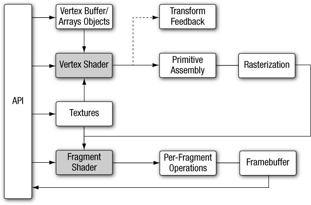
OpenGL ES 3.0 implements a graphics pipeline with programmable shading and consists of two specifications: the OpenGL ES 3.0 API specification and the OpenGL ES Shading Language 3.0 Specification (OpenGL ES SL). Figure 1-1 shows the OpenGL ES 3.0 graphics pipeline. The shaded boxes in this figure indicate the programmable stages of the pipeline in OpenGL ES 3.0. An overview of each stage in the OpenGL ES 3.0 graphics pipeline is presented next.
Vertex Shader
This section gives a high-level overview of vertex shaders. Vertex and fragment shaders are covered in depth in later chapters. The vertex shader implements a general-purpose programmable method for operating on vertices.
The inputs to the vertex shader consist of the following:
• Shader program—Vertex shader program source code or executable that describes the operations that will be performed on the vertex.
• Vertex shader inputs (or attributes)—Per-vertex data supplied using vertex arrays.
• Uniforms—Constant data used by the vertex (or fragment) shader.
• Samplers—Specific types of uniforms that represent textures used by the vertex shader.
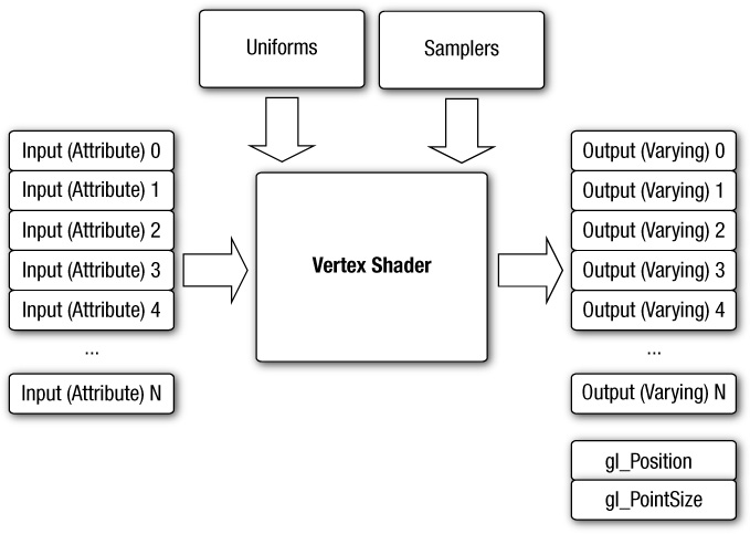
The outputs of the vertex shader were called varying variables in OpenGL ES 2.0, but were renamed vertex shader output variables in OpenGL ES 3.0. In the primitive rasterization stage, the vertex shader output values are calculated for each generated fragment and are passed in as inputs to the fragment shader. The mechanism used to generate a value for each fragment from the vertex shader outputs that is assigned to each vertex of the primitive is called interpolation. Additionally, OpenGL ES 3.0 adds a new feature called transform feedback, which allows the vertex shader outputs to be selectively written to an output buffer (in addition to, or instead of, being passed to the fragment shader). For example, as covered in the transform feedback example in Chapter 14, a particle system can be implemented in the vertex shader in which particles are output to a buffer object using transform feedback. The inputs and outputs of the vertex shader are shown in Figure 1-2.
Vertex shaders can be used for traditional vertex-based operations such as transforming the position by a matrix, computing the lighting equation to generate a per-vertex color, and generating or transforming texture coordinates. Alternatively, because the vertex shader is specified by the application, vertex shaders can be used to perform custom math that enables new transforms, lighting, or vertex-based effects not allowed in more traditional fixed-function pipelines.
Example 1-1 shows a vertex shader written using the OpenGL ES shading language. We explain vertex shaders in significant detail later in the book. We present this shader here just to give you an idea of what a vertex shader looks like. The vertex shader in Example 1-1 takes a position and its associated color data as input attributes, transforms the position using a 4 × 4 matrix, and outputs the transformed position and color.
Example 1-1 A Vertex Shader Example
1. #version 300 es
2. uniform mat4 u_mvpMatrix; // matrix to convert a_position
3. // from model space to normalized
4. // device space
5.
6. // attributes input to the vertex shader
7. in vec4 a_position; // position value
8. in vec4 a_color; // input vertex color
9.
10. // output of the vertex shader - input to fragment
11. // shader
12. out vec4 v_color; // output vertex color
13. void main()
14. {
15. v_color = a_color;
16. gl_Position = u_mvpMatrix * a_position;
17. }
Line 1 provides the version of the Shading Language—information that must appear on the first line of the shader (#version 300 es indicates the OpenGL ES Shading Language v3.00). Line 2 describes a uniform variable u_mvpMatrix that stores the combined model view and projection matrix. Lines 7 and 8 describe the inputs to the vertex shader and are referred to as vertex attributes. a_position is the input vertex position attribute and a_color is the input vertex color attribute. On line 12, we declare the output v_color to store the output of the vertex shader that describes the per-vertex color. The built-in variable called gl_Position is declared automatically, and the shader must write the transformed position to this variable. A vertex or fragment shader has a single entry point called the main function. Lines 13–17 describe the vertex shader main function. In line 15, we read the vertex attribute input a_color and write it as the vertex output color v_color. In line 16, the transformed vertex position is output by writing it to gl_Position.
Primitive Assembly
After the vertex shader, the next stage in the OpenGL ES 3.0 graphics pipeline is primitive assembly. A primitive is a geometric object such as a triangle, line, or point sprite. Each vertex of a primitive is sent to a different copy of the vertex shader. During primitive assembly, these vertices are grouped back into the primitive.
For each primitive, it must be determined whether the primitive lies within the view frustum (the region of 3D space that is visible on the screen). If the primitive is not completely inside the view frustum, it might need to be clipped to the view frustum. If the primitive is completely outside this region, it is discarded. After clipping, the vertex position is converted to screen coordinates. A culling operation can also be performed that discards primitives based on whether they face forward or backward. After clipping and culling, the primitive is ready to be passed to the next stage of the pipeline—the rasterization stage.
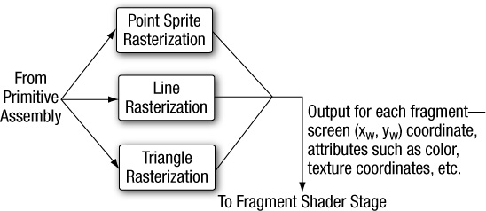
Rasterization
The next stage, shown in Figure 1-3, is the rasterization phase, where the appropriate primitive (point sprite, line, or triangle) is drawn. Rasterization is the process that converts primitives into a set of two-dimensional fragments, which are then processed by the fragment shader. These two-dimensional fragments represent pixels that can be drawn on the screen.
Fragment Shader
The fragment shader implements a general-purpose programmable method for operating on fragments. As shown in Figure 1-4, this shader is executed for each generated fragment by the rasterization stage and takes the following inputs:
• Shader program—Fragment shader program source code or executable that describes the operations that will be performed on the fragment.
• Input variables—Outputs of the vertex shader that are generated by the rasterization unit for each fragment using interpolation.
• Uniforms—Constant data used by the fragment (or vertex) shader.
• Samplers—Specific types of uniforms that represent textures used by the fragment shader.
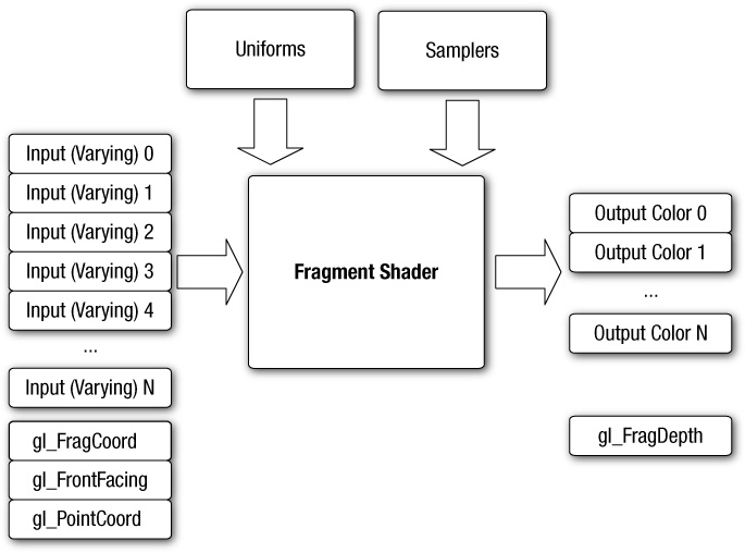
The fragment shader can either discard the fragment or generate one or more color values referred to as outputs. Typically, the fragment shader outputs just a single color value, except when rendering to multiple render targets (see the section Multiple Render Targets in Chapter 11); in the latter case, a color value is output for each render target. The color, depth, stencil, and screen coordinate location (xw, yw) generated by the rasterization stage become inputs to the per-fragment operations stage of the OpenGL ES 3.0 pipeline.
Example 1-2 describes a simple fragment shader that can be coupled with the vertex shader described in Example 1-1 to draw a Gouraud-shaded triangle. Again, we will go into much more detail on fragment shaders later in the book. We present this example just to give you a basic idea of what a fragment shader looks like.
Example 1-2 A Fragment Shader Example
1. #version 300 es
2. precision mediump float;
3.
4. in vec4 v_color; // input vertex color from vertex shader
5.
6. out vec4 fragColor; // output fragment color
7. void main()
8. {
9. fragColor = v_color;
10. }
Just as in the vertex shader, line 1 provides the version of the Shading Language; this information must appear on the first line of the fragment shader (#version 300 es indicates the OpenGL ES Shading Language v3.00). Line 2 sets the default precision qualifier, which is explained in detail in Chapter 4, “Shaders and Programs.” Line 4 describes the input to the fragment shader. The vertex shader must write out the same set of variables that are read in by the fragment shader. Line 6 provides the declaration for the output variable of the fragment shader, which will be the color passed on to the next stage. Lines 7–10 describe the fragment shader main function. The output color is set to the input color v_color. The inputs to the fragment shader are linearly interpolated across the primitive before being passed into the fragment shader.
Per-Fragment Operations
After the fragment shader, the next stage is per-fragment operations. A fragment produced by rasterization with (xw, yw) screen coordinates can only modify the pixel at location (xw, yw) in the framebuffer. Figure 1-5 describes the OpenGL ES 3.0 per-fragment operations stage.
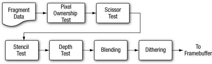
During the per-fragment operations stage, the following functions (and tests) are performed on each fragment, as shown in Figure 1-5:
• Pixel ownership test—This test determines whether the pixel at location (xw, yw) in the framebuffer is currently owned by OpenGL ES. This test allows the window system to control which pixels in the framebuffer belong to the current OpenGL ES context. For example, if a window displaying the OpenGL ES framebuffer window is obscured by another window, the windowing system may determine that the obscured pixels are not owned by the OpenGL ES context and, therefore, the pixels might not be displayed at all. While the pixel ownership test is part of OpenGL ES, it is not controlled by the developer, but rather takes place internally inside of OpenGL ES.
• Scissor test—The scissor test determines whether (xw, yw) lies within the scissor rectangle defined as part of the OpenGL ES state. If the fragment is outside the scissor region, the fragment is discarded.
• Stencil and depth tests—These tests are performed on the stencil and depth value of the incoming fragment to determine whether the fragment should be rejected.
• Blending—Blending combines the newly generated fragment color value with the color values stored in the framebuffer at location (xw, yw).
• Dithering—Dithering can be used to minimize the artifacts that occur as a result of using limited precision to store color values in the framebuffer.
At the end of the per-fragment stage, either the fragment is rejected or a fragment color(s), depth, or stencil value is written to the framebuffer at location (xw, yw). Writing of the fragment color(s), depth, and stencil values depends on whether the appropriate write masks are enabled. Write masks allow finer control over the color, depth, and stencil values written into the associated buffers. For example, the write mask for the color buffer could be set such that no red values are written into the color buffer. In addition, OpenGL ES 3.0 provides an interface to read back the pixels from the framebuffer.
Note
Alpha test and LogicOp are no longer part of the per-fragment operations stage. These two stages exist in OpenGL 2.0 and OpenGL ES 1.x. The alpha test stage is no longer needed because the fragment shader can discard fragments; thus the alpha test can be performed in the fragment shader. In addition, LogicOp was removed because it is used only rarely by applications, and the OpenGL ES working group did not receive requests from independent software vendors (ISVs) to support this feature in OpenGL ES 2.0.
What’s New in OpenGL ES 3.0
OpenGL ES 2.0 ushered in the era of programmable shaders for handheld devices and has been wildly successful in powering games, applications, and user interfaces across a wide range of devices. OpenGL ES 3.0 extends OpenGL ES 2.0 to support many new rendering techniques, optimizations, and visual quality enhancements. The following sections provide a categorized overview of the major new features that have been added to OpenGL ES 3.0. Each of these features will be described in detail later in the book.
Texturing
OpenGL ES 3.0 introduces many new features related to texturing:
• sRGB textures and framebuffers—Allow the application to perform gamma-correct rendering. Textures can be stored in gamma-corrected sRGB space, uncorrected to linear space upon being fetched in the shader, and then converted back to sRGB gamma-corrected space on output to the framebuffer. This enables potentially higher visual fidelity by properly computing lighting and other calculations in linear space.
• 2D texture arrays—A texture target that stores an array of 2D textures. Such arrays might, for example, be used to perform texture animation. Prior to 2D texture arrays, such animation was typically done by tiling the frames of an animation in a single 2D texture and modifying the texture coordinates to change animation frames. With 2D texture arrays, each frame of the animation can be specified in a 2D slice of the array.
• 3D textures—While some OpenGL ES 2.0 implementations supported 3D textures through an extension, OpenGL ES 3.0 has made this a mandatory feature. 3D textures are essential in many medical imaging applications, such as those that perform direct volume rendering of 3D voxel data (e.g., CT, MRI, or PET data).
• Depth textures and shadow comparison—Enable the depth buffer to be stored in a texture. The most common use for depth textures is in rendering shadows, where a depth buffer is rendered from the viewpoint of the light source and then used for comparison when rendering the scene to determine whether a fragment is in shadow. In addition to depth textures, OpenGL ES 3.0 allows the comparison against the depth texture to be done at the time of fetch, thereby allowing bilinear filtering to be done on depth textures (also known as percentage closest filtering [PCF]).
• Seamless cubemaps—In OpenGL ES 2.0, rendering with cubemaps could produce artifacts at the boundaries between cubemap faces. In OpenGL ES 3.0, cubemaps can be sampled such that filtering uses data from adjacent faces and removes the seaming artifact.
• Floating-point textures—OpenGL ES 3.0 greatly expands on the texture formats supported. Floating-point half-float (16-bit) textures are supported and can be filtered, whereas full-float (32-bit) textures are supported but not filterable. The ability to access floating-point texture data has many applications, including high dynamic range texturing to general-purpose computation.
• ETC2/EAC texture compression—While several OpenGL ES 2.0 implementations provided support for vendor-specific compressed texture formats (e.g., ATC by Qualcomm, PVRTC by Imagination Technologies, and Ericsson Texture Compression by Sony Ericsson), there was no standard compression format that developers could rely on. In OpenGL ES 3.0, support for ETC2/EAC is mandatory. The ETC2/EAC formats provide compression for RGB888, RGBA8888, and one- and two-channel signed/unsigned texture data. Texture compression offers several advantages, including better performance (due to better utilization of the texture cache) as well as a reduction in GPU memory utilization.
• Integer textures—OpenGL ES 3.0 introduces the capability to render to and fetch from textures stored as unnormalized signed or unsigned 8-bit, 16-bit, and 32-bit integer textures.
• Additional texture formats—In addition to those formats already mentioned, OpenGL ES 3.0 includes support for 11-11-10 RGB floating-point textures, shared exponent RGB 9-9-9-5 textures, 10-10-10-2 integer textures, and 8-bit-per-component signed normalized textures.
• Non-power-of-2 textures (NPOT)—Textures can now be specified with non-power-of-2 dimensions. This is useful in many situations, such as when texturing from a video or camera feed that is captured/recorded at a non-power-of-2 dimension.
• Texture level of detail (LOD) features—The texture LOD parameter used to determine which mipmap to fetch from can now be clamped. Additionally, the base and maximum mipmap level can be clamped. These two features, in combination, make it possible to stream mipmaps. As larger mipmap levels become available, the base level can be increased and the LOD value can be smoothly increased to provide smooth-looking streaming textures. This is very useful, for example, when downloading texture mipmap data over a network connection.
• Texture swizzles—A new texture object state was introduced to allow independent control of where each channel (R, G, B, and A) of texture data is mapped to in the shader.
• Immutable textures—Provide a mechanism for the application to specify the format and size of a texture before loading it with data. In doing so, the texture format becomes immutable and the OpenGL ES driver can perform all consistency and memory checks up-front. This can improve performance by allowing the driver to skip consistency checks at draw time.
• Increased minimum sizes—All OpenGL ES 3.0 implementations are required to support much larger texture resources than OpenGL ES 2.0. For example, the minimum supported 2D texture dimension in OpenGL ES 2.0 was 64 but was increased to 2048 in OpenGL ES 3.0.
Shaders
OpenGL ES 3.0 includes a major update to the OpenGL ES Shading Language (ESSL; to v3.00) and new API features to support new shader features:
• Program binaries—In OpenGL ES 2.0, it was possible to store shaders in a binary format, but it was still required to link them into program at runtime. In OpenGL ES 3.0, the entire linked program binary (containing the vertex and fragment shader) can be stored in an offline binary format with no link step required at runtime. This can potentially help reduce the load time of applications. Additionally, OpenGL ES 3.0 provides an interface to retrieve the program binary from the driver so no offline tools are required to use program binaries.
• Mandatory online compiler—OpenGL ES 2.0 made it optional whether the driver would support online compilation of shaders. The intent was to reduce the memory requirements of the driver, but this achievement came at a major cost to developers in terms of having to rely on vendor-specific tools to generate shaders. In OpenGL ES 3.0, all implementations will have an online shader compiler.
• Non-square matrices—New matrix types other than square matrices are supported, and associated uniform calls were added to the API to support loading them. Non-square matrices can reduce the instruction count required for performing transformations. For example, if performing an affine transformation, a 4 × 3 matrix can be used in place of a 4 × 4 where the last row is (0, 0, 0, 1), thus reducing the instructions required to perform the transformation.
• Full integer support—Integer (and unsigned integer) scalar and vector types, along with full integer operations, are supported in ESSL 3.00. There are various built-in functions such as conversion from int to float, and from float to int, as well as the ability to read integer values from textures and output integer values to integer color buffers.
• Centroid sampling—To avoid rendering artifacts when multisampling, the output variables from the vertex shader (and inputs to the fragment shader) can be declared with centroid sampling.
• Flat/smooth interpolators—In OpenGL ES 2.0, all interpolators were implicitly linearly interpolated across the primitive. In ESSL 3.00, interpolators (vertex shader outputs/fragment shader inputs) can be explicitly declared to have either smooth or flat shading.
• Uniform blocks—Uniform values can be grouped together into uniform blocks. Uniform blocks can be loaded more efficiently and also shared across multiple shader programs.
• Layout qualifiers—Vertex shader inputs can be declared with layout qualifiers to explicitly bind the location in the shader source without requiring making API calls. Layout qualifiers can also be used for fragment shader outputs to bind the outputs to each target when rendering to multiple render targets. Further, layout qualifiers can be used to control the memory layout for uniform blocks.
• Instance and vertex ID—The vertex index is now accessible in the vertex shader as well as the instance ID if using instance rendering.
• Fragment depth—The fragment shader can explicitly control the depth value for the current fragment rather than relying on the interpolation of its depth value.
• New built-in functions—ESSL 3.00 introduces many new built-in functions to support new texture features, fragment derivatives, half-float data conversion, and matrix and math operations.
• Relaxed limitations—ESSL 3.0 greatly relaxes the restrictions on shaders. Shaders are no longer limited in terms of instruction length, fully support looping and branching on variables, and support indexing on arrays.
Geometry
OpenGL ES 3.0 introduces several new features related to geometry specification and control of primitive rendering:
• Transform feedback—Allows the output of the vertex shader to be captured in a buffer object. This is useful for a wide range of techniques that perform animation on the GPU without any CPU intervention—for example, particle animation or physics simulation using render-to-vertex-buffer.
• Boolean occlusion queries—Enable the application to query whether any pixels of a draw call (or a set of draw calls) passes the depth test. This feature can be used within a variety of techniques, such as visibility determination for a lens flare effect as well as optimization to avoid performing geometry processing on objects whose bounding volume is obscured.
• Instanced rendering—Efficiently renders objects that contain similar geometry but differ by attributes (such as transformation matrix, color, or size). This feature is useful in rendering large quantities of similar objects, such as for crowd rendering.
• Primitive restart—When using triangle strips in OpenGL ES 2.0 for a new primitive, the application would have to insert indices into the index buffer to represent a degenerate triangle. In OpenGL ES 3.0, a special index value can be used that indicates the beginning of a new primitive. This obviates the need for generating degenerate triangles when using triangle strips.
• New vertex formats—New vertex formats, including 10-10-10-2 signed and unsigned normalized vertex attributes; 8-bit, 16-bit, and 32-bit integer attributes; and 16-bit half-float, are supported in OpenGL ES 3.0.
Buffer Objects
OpenGL ES 3.0 introduces many new buffer objects to increase the efficiency and flexibility of specifying data to various parts of the graphics pipeline:
• Uniform buffer objects—Provide an efficient method for storing/binding large blocks of uniforms. Uniform buffer objects can be used to reduce the performance cost of binding uniform values to shaders, which is a common bottleneck in OpenGL ES 2.0 applications.
• Vertex array objects—Provide an efficient method for binding and switching between vertex array states. Vertex array objects are essentially container objects for vertex array states. Using them allows an application to switch the vertex array state in a single API call rather than making several calls.
• Sampler objects—Separate the sampler state (texture wrap mode and filtering) from the texture object. This provides a more efficient method of sharing the sampler state across textures.
• Sync objects—Provide a mechanism for the application to check on whether a set of OpenGL ES operations has finished executing on the GPU. A related new feature is a fence, which provides a way for the application to inform the GPU that it should wait until a set of OpenGL ES operations has finished executing before queuing up more operations for execution.
• Pixel buffer objects—Enable the application to perform asynchronous transfer of data to pixel operations and texture transfer operations. This optimization is primarily intended to provide faster transfer of data between the CPU and the GPU, where the application can continue doing work during the transfer operation.
• Buffer subrange mapping—Allows the application to map a subregion of a buffer for access by the CPU. This can provide better performance than traditional buffer mapping, in which the whole buffer needs to be available to the client.
• Buffer object to buffer object copies—Provide a mechanism to efficiently transfer data from one buffer object to another without intervention on the CPU.
Framebuffer
OpenGL ES 3.0 adds many new features related to off-screen rendering to framebuffer objects:
• Multiple render targets (MRTs)—Allow the application to render simultaneously to several color buffers at one time. With MRTs, the fragment shader outputs several colors, one for each attached color buffer. MRTs are used in many advanced rendering algorithms, such as deferred shading.
• Multisample renderbuffers—Enable the application to render to off-screen framebuffers with multisample anti-aliasing. The multisample renderbuffers cannot be directly bound to textures, but they can be resolved to single-sample textures using the newly introduced framebuffer blit.
• Framebuffer invalidation hints—Many implementations of OpenGL ES 3.0 are based on GPUs that use tile-based rendering (TBR; explained in the Framebuffer Invalidation section in Chapter 12). It is often the case that TBR incurs a significant performance cost when having to unnecessarily restore the contents of the tiles for further rendering to a framebuffer. Framebuffer invalidation gives the application a mechanism to inform the driver that the contents of the framebuffer are no longer needed. This allows the driver to take optimization steps to skip unnecessary restore operations on the tiles. Such functionality is very important to achieve peak performance in many applications, especially those that do significant amounts of off-screen rendering.
• New blend equations—The min/max functions are supported in OpenGL ES 3.0 as a blend equation.
OpenGL ES 3.0 and Backward Compatibility
OpenGL ES 3.0 is backward compatible with OpenGL ES 2.0. This means that just about any application written to use OpenGL ES 2.0 will run on implementations of OpenGL ES 3.0. There are some very minor changes to the later version that will affect a small number of applications in terms of backward compatibility. Namely, framebuffer objects are no longer shared between contexts, cubemaps are always filtered using seamless filtering, and there are minor changes in the way signed fixed-point numbers are converted to floating-point numbers.
The fact that OpenGL ES 3.0 is backward compatible with OpenGL ES 2.0 differs from what was done for OpenGL ES 2.0 with respect to its backward compatibility with previous versions of OpenGL ES. OpenGL ES 2.0 is not backward compatible with OpenGL ES 1.x. OpenGL ES 2.0/3.0 do not support the fixed-function pipeline that OpenGL ES 1.x supports. The OpenGL ES 2.0/3.0 programmable vertex shader replaces the fixed-function vertex units implemented in OpenGL ES 1.x. The fixed-function vertex units implement a specific vertex transformation and lighting equation that can be used to transform the vertex position, transform or generate texture coordinates, and calculate the vertex color. Similarly, the programmable fragment shader replaces the fixed-function texture combine units implemented in OpenGL ES 1.x. The fixed-function texture combine units implement a texture combine stage for each texture unit. The texture color is combined with the diffuse color and the output of the previous texture combine stage with a fixed set of operations such as add, modulate, subtract, and dot.
The OpenGL ES working group decided against backward compatibility between OpenGL ES 2.0/3.0 and OpenGL ES 1.x for the following reasons:
• Supporting the fixed-function pipeline in OpenGL ES 2.0/3.0 implies that the API would support more than one way of implementing a feature, in violation of one of the criteria used by the working group in determining which features should be supported. The programmable pipeline allows applications to implement the fixed-function pipeline using shaders, so there is really no compelling reason to be backward compatible with OpenGL ES 1.x.
• Feedback from ISVs indicated that most games do not mix programmable and fixed-function pipelines. That is, games are written either for a fixed-function pipeline or for a programmable pipeline. Once you have a programmable pipeline, there is no reason to use a fixed-function pipeline, as you have much more flexibility in the effects that can be rendered.
• The OpenGL ES 2.0/3.0 driver’s memory footprint would be much larger if it had to support both the fixed-function and programmable pipelines. For the devices targeted by OpenGL ES, minimizing memory footprint is an important design criterion. Separating the fixed-function support into the OpenGL ES 1.x API and placing the programmable shader support into the OpenGL ES 2.0/3.0 APIs meant that vendors that do not require OpenGL ES 1.x support no longer need to include this driver.
EGL
OpenGL ES commands require a rendering context and a drawing surface. The rendering context stores the appropriate OpenGL ES state. The drawing surface is the surface to which primitives will be drawn. The drawing surface specifies the types of buffers that are required for rendering, such as a color buffer, depth buffer, and stencil buffer. The drawing surface also specifies the bit depths of each of the required buffers.
The OpenGL ES API does not mention how a rendering context is created or how the rendering context gets attached to the native windowing system. EGL is one interface between the Khronos rendering APIs such as OpenGL ES and the native window system; there is no hard-and-fast requirement to provide EGL when implementing OpenGL ES. Developers should refer to the platform vendor’s documentation to determine which interface is supported. As of this writing, the only known platform supporting OpenGL ES that does not support EGL is iOS.
Any OpenGL ES application will need to perform the following tasks using EGL before any rendering can begin:
• Query the displays that are available on the device and initialize them. For example, a flip phone might have two LCD panels, and it is possible that we might use OpenGL ES to render to surfaces that can be displayed on either or both panels.
• Create a rendering surface. Surfaces created in EGL can be categorized as on-screen surfaces or off-screen surfaces. On-screen surfaces are attached to the native window system, whereas off-screen surfaces are pixel buffers that do not get displayed but can be used as rendering surfaces. These surfaces can be used to render into a texture and can be shared across multiple Khronos APIs.
• Create a rendering context. EGL is needed to create an OpenGL ES rendering context. This context needs to be attached to an appropriate surface before rendering can actually begin.
The EGL API implements the features just described as well as additional functionality such as power management, support for multiple rendering contexts in a process, sharing objects (such as textures or vertex buffers) across rendering contexts in a process, and a mechanism to get function pointers to EGL or OpenGL ES extension functions supported by a given implementation.
The latest version of the EGL specification is EGL version 1.4.
Programming with OpenGL ES 3.0
To write any OpenGL ES 3.0 application, you need to know which header files must be included and with which libraries your application needs to link. It is also useful to understand the syntax used by the EGL and GL command names and command parameters.
Libraries and Include Files
OpenGL ES 3.0 applications need to link with the following libraries: the OpenGL ES 3.0 library named libGLESv2.lib and the EGL library named libEGL.lib.
OpenGL ES 3.0 applications also need to include the appropriate ES 3.0 and EGL header files. The following include files must be included by any OpenGL ES 3.0 application:
#include <EGL/egl.h>
#include <GLES3/gl3.h>
egl.h is the EGL header file and gl3.h is the OpenGL ES 3.0 header file. Applications can optionally include gl2ext.h, which is the header file that describes the list of Khronos-approved extensions for OpenGL ES 2.0/3.0.
The header file and library names are platform dependent. The OpenGL ES working group has tried to define the library and header names and indicate how they should be organized, but this arrangement might not be found on all OpenGL ES platforms. Developers should, however, refer to the platform vendor’s documentation for information on how the libraries and include files are named and organized. The official OpenGL ES header files are maintained by Khronos and available from http://khronos.org/registry/gles/. The sample code for the book also includes a copy of the header files (working with the sample code is described in the next chapter).
EGL Command Syntax
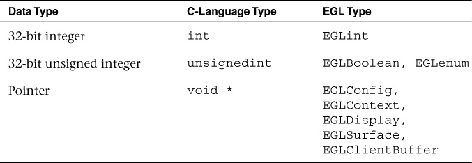
All EGL commands begin with the prefix egl and use an initial capital letter for each word making up the command name (e.g., eglCreateWindowSurface). Similarly, EGL data types also begin with the prefix Egl and use an initial capital letter for each word making up the type name, except for EGLint and EGLenum.
Table 1-1 briefly describes the EGL data types used.
OpenGL ES Command Syntax
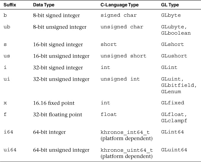
All OpenGL ES commands begin with the prefix gl and use an initial capital letter for each word making up the command name (e.g., glBlendEquation). Similarly, OpenGL ES data types also begin with the prefix GL.
In addition, some commands might take arguments in different flavors. The flavors or types vary in terms of the number of arguments taken (one to four arguments), the data type of the arguments used (byte [b], unsigned byte [ub], short [s], unsigned short [us], int [i], and float [f]), and whether the arguments are passed as a vector (v). A few examples of command flavors allowed in OpenGL ES follow.
The following two commands are equivalent except that one specifies the uniform value as floats and the other as integers:
glUniform2f(location, l.Of, O.Of);
glUniform2i(location, 1, 0)
The following lines describe commands that are also equivalent, except that one passes command arguments as a vector and the other does not:
GLfloat coord[4] = { l.Of, 0.75f, 0.25f, O.Of };
glUniform4fv(location, coord);
glUniform4f(location, coord[0], coord[l], coord[2], coord[3]);
Table 1-2 describes the command suffixes and argument data types used in OpenGL ES.
Finally, OpenGL ES defines the type GLvoid. This type is used for OpenGL ES commands that accept pointers.
In the rest of this book, OpenGL ES commands are referred to by their base names only, and an asterisk is used to indicate that this base name refers to multiple flavors of the command name. For example, glUniform*() stands for all variations of the command you use to specify uniforms and glUniform*v() refers to all the vector versions of the command you use to specify uniforms. If a particular version of a command needs to be discussed, we use the full command name with the appropriate suffixes.
Error Handling
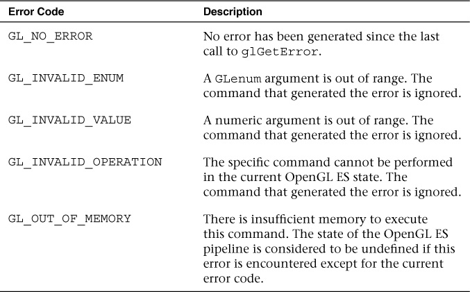
OpenGL ES commands incorrectly used by applications generate an error code. This error code is recorded and can be queried using glGetError. No other errors will be recorded until the application has queried the first error code using glGetError. Once the error code has been queried, the current error code is reset to GL_NO_ERROR. The command that generated the error is ignored and does not affect the OpenGL ES state except for the GL_OUT_OF_MEMORY error described later in this section.
The glGetError command is described next.
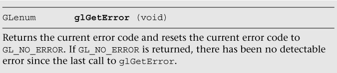
Table 1-3 lists the basic error codes and their description. Other error codes besides the basic ones listed in this table are described in the chapters that cover OpenGL ES commands that generate these specific errors.
Basic State Management
Figure 1-1 showed the various pipeline stages in OpenGL ES 3.0. Each pipeline stage has a state that can be enabled or disabled and appropriate state values that are maintained per context. Examples of states are blending enable, blend factors, cull enable, and cull face. The state is initialized with default values when an OpenGL ES context (EGLContext) is initialized. The state enables can be set using the glEnable and glDisable commands.
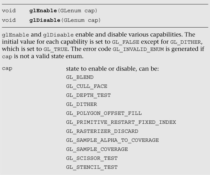
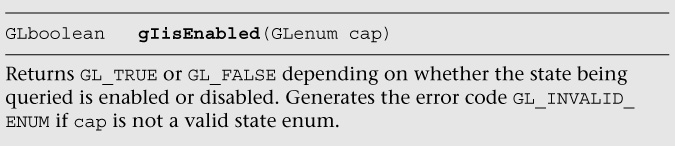
Later chapters will describe the specific state enables for each pipeline stage shown in Figure 1-1. You can also check whether a state is currently enabled or disabled by using the glisEnabled command.
Specific state values such as blend factor, depth test values, and so on can also be queried using appropriate glGet*** commands. These commands are described in detail in Chapter 15, “State Queries.”
Further Reading
The OpenGL ES 1.0, 1.1, 2.0, and 3.0 specifications can be found at khronos.org/opengles/. In addition, the Khronos website (khronos.org) has the latest information on all Khronos specifications, developer message boards, tutorials, and examples.
• Khronos OpenGL ES 1.1 website: http://khronos.org/opengles/1_X/
• Khronos OpenGL ES 2.0 website: http://khronos.org/opengles/2_X/
• Khronos OpenGL ES 3.0 website: http://khronos.org/opengles/3_X/
• Khronos EGL website: http://khronos.org/egl/