The OpenGL Shading Language, commonly called the “GLSL,” defines a number of variables for matching OpenGL state and large set of convenience functions. This appendix[1] provides a complete list of GLSL built-in variables and functions.
[1] This appendix is adapted from The OpenGL® Shading Language Specification (Versions 1.30 and 1.40) by John Kessenich.
The OpenGL Shading Language has been updated including deprecating and removing some features.
Version 1.30 of GLSL added numerous new functions and data types, while maintaining complete backward compatibility with previous versions of GLSL. No features were removed through deprecation, although various variables and state were deprecated.
Version 1.40, while aligning with the removed features of OpenGL, removed several features as well. Those removed features are made available again if the GL_ARB_compatibility extension is available with your implementation. Removed features (which are supported with the compatibility extension) are listed in the margin.
For OpenGL versions up to and including 3.0, much of the OpenGL state associated with the fixed-function pipeline that an application can configure is also available as variables from within a GLSL shader. The next sections describe all state variables available to shaders, and any restrictions on their use.
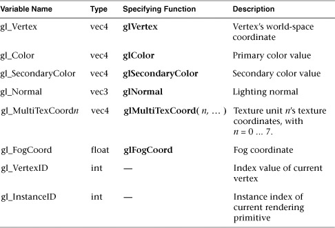
Table I-1 lists the set of global attribute values reflecting the per-vertex input data that can be accessed exclusively from within a vertex shader. Almost all of these values were deprecated in Version 1.30.
|
Compatibility Extension |
|
gl_Vertex |
|
gl_Color |
|
gl_ SecondaryColor |
|
gl_Normal |
|
gl_ MultiTexCoordn |
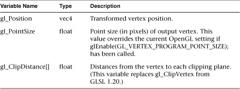
The following variables are used in later stages of the vertex processing pipeline, and are only available in vertex shaders.
In particular, the gl_Position variable is the only required output of vertex shaders, and specifies the final, projected position of the input vertex. Generally, this is accomplished by directly multiplying the input vertex by the combined modelview and projection transformations, as in the following example:
gl_Position = gl_ModelViewProjectionMatrix * gl_Vertex;
Table I-2 enumerates the special output variables of a vertex shader.
|
Compatibility Extension |
|
gl_ClipVertex |
While user-defined varying variables are shared between vertex and fragment shaders, certain OpenGL-defined varying variables are accessible only in vertex shader, with their values being assigned to a unique set of (corresponding, but differently named) varying values that are available only in fragment shaders.
Table I-3 lists the variables that are only available in vertex shaders.

|
Compatibility Extension |
|
gl_Front*Color |
|
gl_Back*Color |
|
gl_TexCoord |
|
gl_FogFragCoord |
Table I-4 lists the set of input varying variables available in fragment shaders.

|
Compatibility Extension |
|
gl_*Color |
|
gl_TexCoord |
|
gl_FogFragCoord |
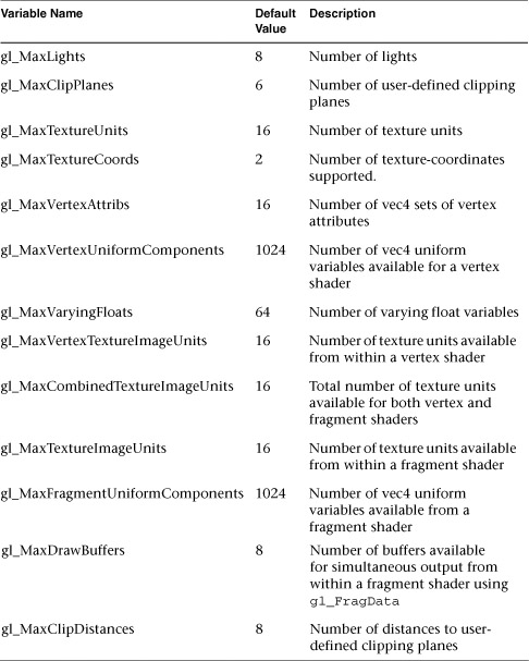
Most implementation-dependent maximum values are reflected as constant integer variables accessible in both vertex and fragment shaders. The variables listed in Table I-5 represent the minimum capabilities of an OpenGL implementation, and all are represented as a single constant integer expression.
|
Compatibility Extension |
|
gl_MaxClipPlanes |
|
gl_MaxVarying Floats |
The following sets of variables are available in both vertex and fragment shaders, and reflect the OpenGL state settings specified by the application.
Note
All built-in uniform state, with the exception of gl_DepthRange, was deprecated in GLSL 1.30, and effectively removed. All of the functionality is available if your implementation includes the GL_ARB_compatibility extension.
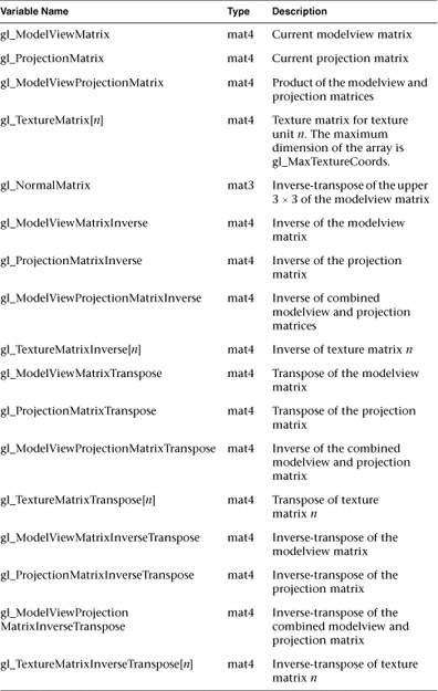
The following variables represent the matrix transformation states of OpenGL. Various matrices are derived from the values set within an OpenGL application. For example, lighting normals (see “Define Normal Vectors for Each Vertex of Every Object” in Chapter 5) are transformed by the inverse-transpose of the upper-left 3 × 3 part of the modelview matrix, which is automatically computed for you when changes are made to the modelview matrix and presented using the gl_NormalMatrix variable.
Derived matrices (particularly those involving matrix inverses) may be undefined if the source matrix is ill-conditioned or singular.
Table I-6 lists the available matrices in GLSL.
|
Compatibility Extension |
|
All fixed-function matrices |
Vertex normals can be normalized within a shader by using the normalize() function. However, if normals were uniformly scaled (all calls to glScale() had the same values for x, y, and z), they could be normalized by a simple scaling operation (thus saving the potentially expensive square root operation required by normalize()). The scaling factor is stored in:
uniform float gl_NormalScale;
and applied as
vec3 normal = gl_NormalScale * gl_Normal;
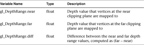
Access to the depth range values (as set by glDepthRange()) can be accessed using:
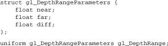
Table I-7 provides descriptions for each of the depth range variables.
Access to the user-defined clipping planes (as specified by glClipPlane()) can be accessed in a shader through the array:
uniform vec4 gl_ClipPlane[gl_MaxClipPlanes];
|
Compatibility Extension |
|
gl_ClipPlanes |
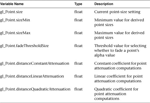
Parameters controlling the size and shading of points are controlled by the state set by calling glPointParameter(). The following structure allows access to all point parameter settings:

|
Compatibility Extension |
|
gl_Point |
The variables associated with point sizes and parameters are listed in Table I-8.
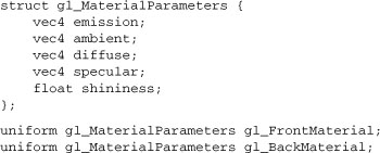
Material state, as specified by calling glMaterial(), can be queried by utilizing the values in the following structure, which stores material properties for both the front- and back-material state:
|
Compatibility Extension |
|
gl_FrontMaterial |
|
gl_BackMaterial |
Table I-9 lists the material variables and their descriptions.

The state associated with each light in OpenGL is stored in the following structure. For this section, the notation described in “The Mathematics of Lighting” on page 240 is used.
|
Compatibility Extension |
|
gl_LightSource |
|
gl_LightModel |
|
gl_ FrontLightProduct |
|
gl_ BackLightProduct |
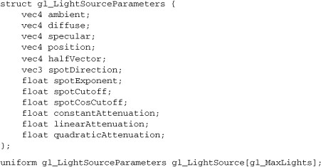
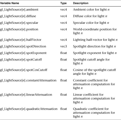
Table I-10 provides a list of the parameters associated with each light source available in a shader.
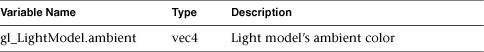
The following structure contains the values for the light-model parameters.
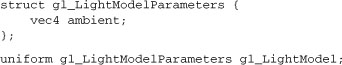
The values associated with the light model are described in Table I-11.
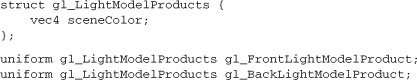
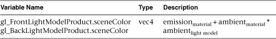
To help reduce the computation required for computing the colors based on OpenGL’s Phone lighting model, the non-light dependent terms of the lighting equation (the emission and ambient material terms) combined with the light model ambient value are cached in the following structure and are described in Table I-12.
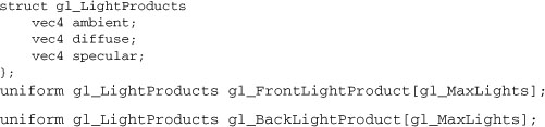
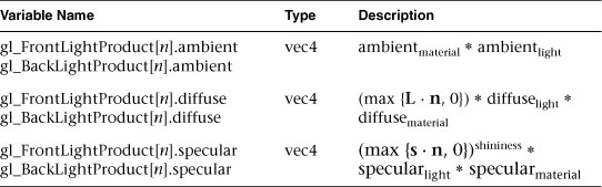
Similarly, various products of constant factors of the material and lights are cached in the following structure and described in Table I-13.
The texture environment color (as specified by glTexEnv()) for each texture unit is available by accessing:
uniform vec4 gl_TextureEnvColor[gl_MaxTextureImageUnits];
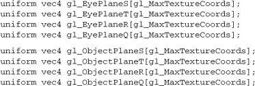
The user-defined planes for texture coordinate generation are available by accessing the following sets of values, one for each set of texture coordinates:
|
Compatibility Extension |
|
gl_EyePlane* |
|
gl_ObjectPlane* |
The state associated with fog and atmospheric effects (see “Fog” in Chapter 6) in OpenGL is stored in the following structure and described in Table I-14.
|
Compatibility Extension |
|
gl_Fog |


Table I-15 describes the trigonometric functions available in GLSL shaders. Angles are measured in radians, and the following commands operate on each component separately. TYPE represents one of float, vec2, vec3, or vec4.
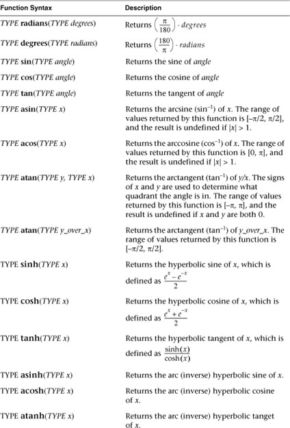
Table I-16 lists the logarithmic and exponential functions available in GLSL. The commands operate on each component separately. TYPE represents one of float, vec2, vec3, or vec4.
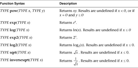
Table I-17 lists the basic numerical functions that GLSL supports. Each command operates on each component separately. TYPE represents one of float, vec2, vec3, or vec4. iTYPE represents one of int, ivec2, ivec3, or ivec4. Similarly, uTYPE represents one of uint, uvec2, uvec3, or uvec4.
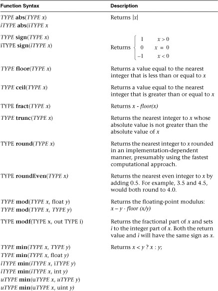

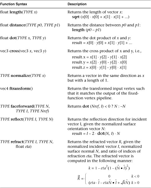
Table I-18 describes the vector operations in GLSL. The following commands operate on their arguments as vectors. Where not explicitly specified, TYPE represents one of: float, vec2, vec3, or vec4.
|
Compatibility Extension |
|
ftransform() |
As compared to standard matrix multiplication, which is defined using the * operator, the matrixCompMult() routine, described in Table I-19, produces a component-wise multiplication of two equally dimensioned matrices.

The following functions produce a vector of Boolean values representing the results of the specified operation conducted on each pair of components from the input vectors. TYPE represents any of vec2, vec3, vec4, ivec2, ivec3, ivec4, uvec2, uvec3, or uvec4 in the prototypes below, or a Boolean vector when explicitly specified. The input vectors must be of the same type, and the Boolean vector returned, represented by bvec below, will have the same size at the input vectors.
Table I-20 describes the accepted vector functions.

Texture lookup functions are available to both vertex and fragment shaders if supported by the underlying OpenGL implementation. All of these functions rely on the use of samplers, which provide a handle for accessing the texture map specified by the application using the OpenGL API. The different types of samplers are detailed in “Accessing Texture Maps in Shaders” in Chapter 15.
In the following tables, sampler types (e.g., floating point, signed, and unsigned integer) are generically represented by “SAMPLER” with the specific texture type appended (e.g., SAMPLER2DArray). Likewise, optional parameters are denoted in square brackets ([...]).
The functions in Tables I-29 through I-32 provide access to textures through samplers, as set up through the OpenGL API. Texture properties such as size, pixel format, number of dimensions, filtering method, number of mipmap levels, depth comparison, and so on are also defined by OpenGL API calls. Such properties are taken into account as the texture is accessed via the built-in functions defined below.
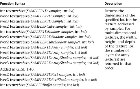
The following routines will return the sizes (as a set of integers) for each dimension of a texture level (lod):
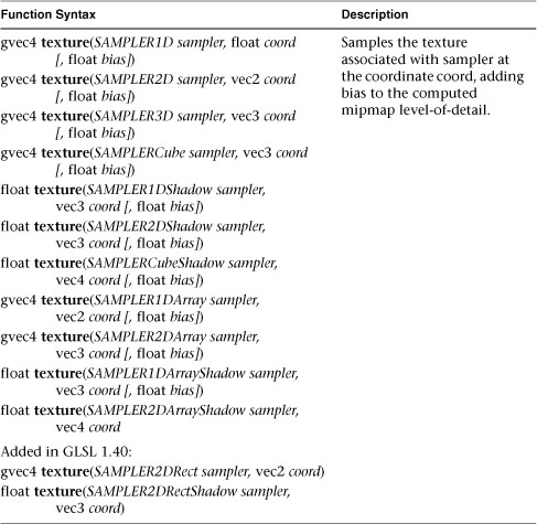
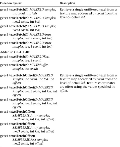
The following functions use the provided texture coordinates to retrieve a texel from the texture map associated with sampler.
All forms are accepted by fragment shaders. Functions with the bias parameter are not accepted in vertex shaders.
The optional bias parameter is used to alter which mipmap is sampled (see “Calculating the Mipmap Level” in Chapter 9). If a bias value is provided while accessing a texture that does not contain mipmaps, the texture is accessed directly, and the value is ignored. The bias forms of the texture functions are available only in fragment shaders.
Sample a texture using a constant offset that is applied to the texture coordinates provided. If a bias value is specified, it is added to the mipmap lod parameter before sampling. The bias form is not valid in vertex shaders.

The following functions retrieve a single texel (without filtering) from a texture. The *Offset forms offset the supplied texture coordinates by an offset, similar to the textureOffset() functions.
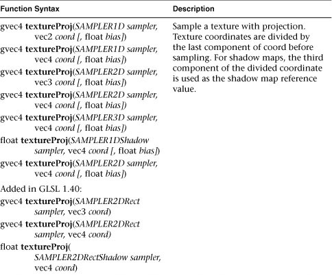
The following functions retrieve a texel from the texture map associated with sampler. Before the texel is retrieved, all components of the input texture coordinate, coord, are divided by the last coordinate.
All forms are accepted by fragment shaders. Functions with the bias parameter are not accepted in vertex shaders.
Once again, the optional bias parameter is used to alter which mipmap is sampled (see “Calculating the Mipmap Level” in Chapter 9). If a bias value is provided while accessing a texture that does not contain mipmaps, the texture is accessed directly and the value is ignored. The bias forms of the texture functions are available only in fragment shaders.
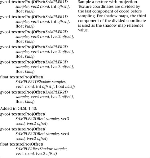
The *Offset forms apply the specified offset, similar to the operation of the texelOffset() routines, to the provided coordinates before the projective divide and texture sampling.
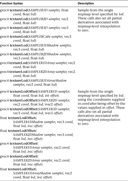
The following functions retrieve texels only from a single mipmap level explicitly specified by the lod parameter.
The *Offset forms apply the specified offset, similar to the operation of the texelOffset() routines, to the provided coordinates before texture sampling.
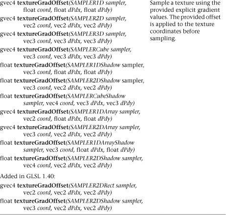
The following functions sample a texture using the user-supplied gradients in the mipmap level determination. The *Offset forms apply the specified offset, similar to the operation of the texelOffset() routines, to the provided coordinates before texture sampling.

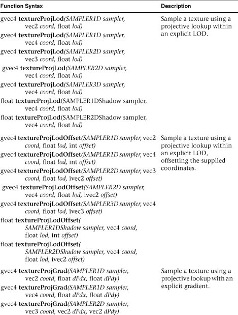
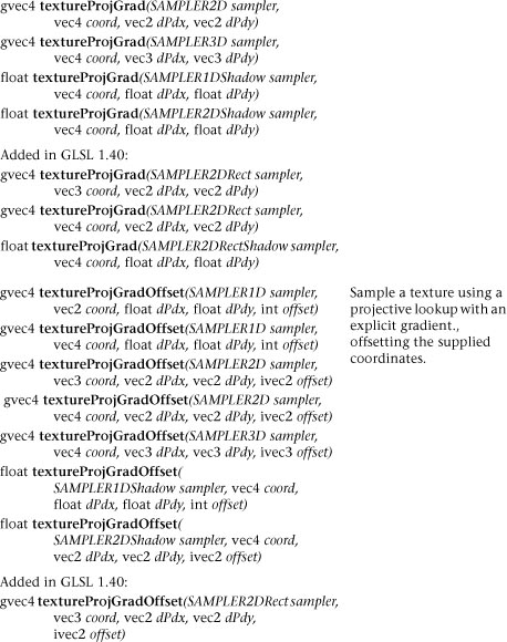
The following routines provide combinations of the other routines for texture access. For example, the textureProjLod() function does a projective texture sample on a single mipmap level. As always, the *Offset() variants apply a coordinate offset before sampling the texture, similar to textureOffset().

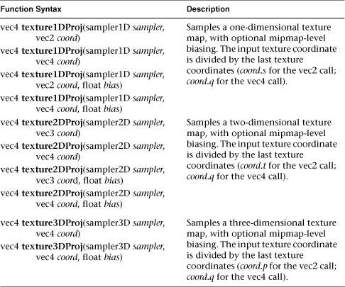
The following set of functions were deprecated in GLSL Version 1.30, but had not been removed from the language as of the time of this book’s publication.
The following functions retrieve a texel from the texture map associated with sampler. Before the texel is retrieved, all components of the input texture coordinate, coord, are divided by the last coordinate.

All forms are accepted by fragment shaders. Functions with the bias parameter are not accepted in vertex shaders.
Once again, The optional bias parameter is used to alter which mipmap is sampled (see “Calculating the Mipmap Level” in Chapter 9). If a bias value is provided while accessing a texture that does not contain mipmaps, the texture is accessed directly and the value is ignored. The bias forms of the texture functions are only available in fragment shaders.
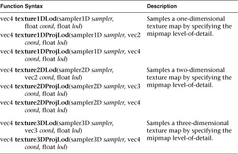
Texel retrieval in vertex shaders does not include the automatic computation of a mipmap level, as happens in a fragment shader. The following functions allow for the sampling of mipmapped textures by vertex shaders by providing an mipmap level-of-detail, or lod value (see “Calculating the Mipmap Level” in Chapter 9 for how to compute the level-of-detail value).
The vertex shader versions of the texture access functions are available in non-projective and projective forms (those calls that include “Proj” in the name. The input texture coordinates for the projective forms are processed as described in “Projective Texture Access Functions” on page 33.
Retrieve the texel at input texture coordinate, coord, in the cube map texture currently bound to sampler. The direction of coord is used to select which face to do a two-dimensional texture lookup in.

If a non-shadow texture call is made to a sampler that represents a depth texture with depth comparisons turned on, then results are undefined. If a shadow texture call is made to a sampler that represents a depth texture with depth comparisons turned off, then results are undefined. If a shadow texture call is made to a sampler that does not represent a depth texture, then results are undefined.
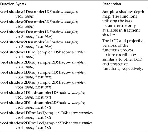
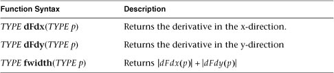
Table I-34 describes the functions for accessing a fragment’s derivative, which are computed as the fragments of the underlying geometric primitive are rasterized.
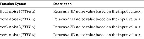
The stochastic noise functions described in Table I-35 are available in both vertex and fragment shaders. The computed noise values returned are pseudo-random, but repeatable provided the same random number seed is used.