7
OpenShift Network
As we know, networking can be the cause of big trouble if it is not well designed. From a traditional perspective, the network is the dorsal spine of every infrastructure. Networking equipment such as routers, modems, switches, firewalls, Web Application Firewalls (WAFs), Intrusion Detection Systems/Intrusion Prevention Systems (IDSs/IPSs), proxies, and Virtual Private Networks (VPNs) needs to be totally integrated, deployed, and maintained using best practices to ensure high performance and reliable network infrastructure. In this chapter, we will discuss important concepts related to networking on OpenShift that you need to take into consideration to make the best decisions for your case.
This chapter covers the following topics:
- OpenShift networking
- Network policies
- What is an Ingress controller?
- Types of routes
OpenShift networking
Throughout this book, we continue to reaffirm the importance of choosing the right architecture as it directly impacts the way the cluster will work. We expect that, at this time, all the required network decisions have been made and implemented already – there are a lot of network changes that are not possible after cluster deployment.
Although we already discussed networks in Chapter 2, Architecture Overview and Definitions, and deployed our cluster, we believe that it is important to expand on this topic a bit more and include more details about the differences when considering network usage.
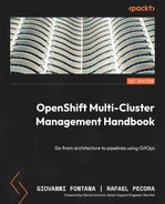
Red Hat OpenShift uses a default Software-Defined Network (SDN) based on Open vSwitch (https://github.com/openvswitch/ovs) that creates a multilayer network solution. This additional layer works as a virtual switch on top of the network layer, and it is responsible for creating, maintaining, and isolating traffic on the virtual LAN.
Because of its multiple-layer network capacity, Open vSwitch provides a way to control traffic coming in and out of the cluster. Refer to the following diagram to better understand network traffic between network layers:
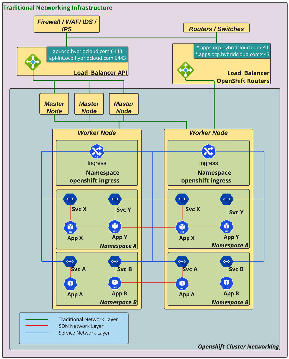
Figure 7.1 – Overview of the networking layers
During the OpenShift cluster installation, some namespaces related to network functions are created; basically, the most important network project is openshift-sdn, which contains some pods for each node that will be responsible for the traffic between the nodes. It is relevant to also state that the traffic is running inside a virtual LAN operated by Open vSwitch. There are other network projects involved as well, such as openshift-host-network and openshift-ingress.
How does traffic work on Open vSwitch?
To answer this question, we need to define where the traffic begins. Let’s start with the internal traffic, which means the communication between the application’s pods that are inside the OpenShift cluster.
To facilitate your understanding, consider two applications running on OpenShift; the first one is named app-frontend and the second app-backend. As the name suggests, app-frontend makes API calls to app-backend to process user requests.
Therefore, when a pod from the app-frontend application makes a request to the app-backend application, this request will be sent to the internal service, in this case the app-backend service. The app-backend service is responsible for delivering that package to one of the app-backend pods. In the same way, the application handles its request and sends the result package back to the service network, which, at this point, already has a connection established with app-frontend.
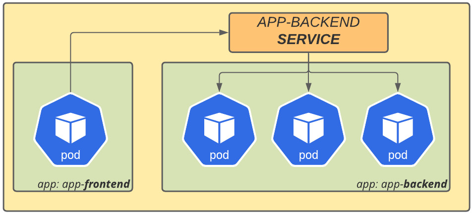
Figure 7.2 – Service network layer
With that, we have briefly explained the traffic between applications inside the cluster. Now, let’s see how external-to-internal traffic is handled. When a request comes from outside the cluster, it goes initially to the external load balancer. As the load balancer receives a connection, it routes the request to one of the OpenShift Ingress pods, which sends it to the service of the destination application, which, in turn, routes it to the proper application’s pod.
Figure 7.3 – Route SDN networking
Now that you understand how traffic works in an OpenShift cluster, it is important to reinforce that OpenShift basically works with three network layers: the node network, the service network, and the cluster network (aka the pods network).
The node network is the physical network used to create and maintain machines. The service network is a virtual layer created by Open vSwitch that is responsible for routing traffic between pods and services. The cluster network is another Open vSwitch virtual layer responsible for creating subnets for the communication of pods – it allows isolating traffic between projects as needed.
In the next sections, we will look deeper into the main available networking plugins for OpenShift. Keep in mind that there are subtle differences between the aforementioned plugins, so the decision between using one plugin and another must be taken into account according to the differences in functionality, which can somewhat affect the architecture of the cluster, and also the network functionality available to the applications. This is a decision that must be made together with the network and software architecture team, to understand the current use cases and planned future implementations, aiming for an efficient and functional cluster.
Network type – OpenShift SDN or OVN-Kubernetes
OpenShift is a complete PaaS solution based on Kubernetes that provides several options other than its default components. For instance, OpenShift, by default, uses the Open vSwitch network plugin (OpenShift SDN), but you can use OVN-Kubernetes as an alternative.
A network plugin is a feature that creates an overlay network using the Kubernetes Container Network Interface (CNI) that isolates the traffic between the virtual machines network and the OpenShift nodes.
These two supported options offer a good and reliably performing network, but you can use other kinds of CNI depending on the scenario where OpenShift has been provisioned. Check the link for OpenShift Tested Integrations in the Further reading section of this chapter to see the options that are tested and supported by Red Hat.
Network policies
As we already mentioned, OpenShift uses an SDN, and preferably, the network traffic control should be done using the features the cluster provides itself. In our experience, having implemented OpenShift in many organizations, we have often heard doubts regarding how to control network traffic within the cluster, as most customers are used to doing it by using regular firewall devices. In this section, we will walk you through how to control network traffic to be able to allow or deny network traffic as needed. Before giving you some options to do that, we first need to differentiate the different traffic directions that we have in a cluster.
North-south traffic
OpenShift has been designed to cover the most common scenarios, even regarding networking. When an incoming connection comes from outside the cluster to an application, it is possible to control network traffic into the cluster using an external firewall and/or the OpenShift Ingress solution.
East-west traffic
Initially, it may sound a little weird to say that there is also network traffic in east-west directions but east-west network traffic is nothing more than traffic between applications in different namespaces inside the same OpenShift cluster.
The following diagram explains how these different types of traffic occur in a cluster:
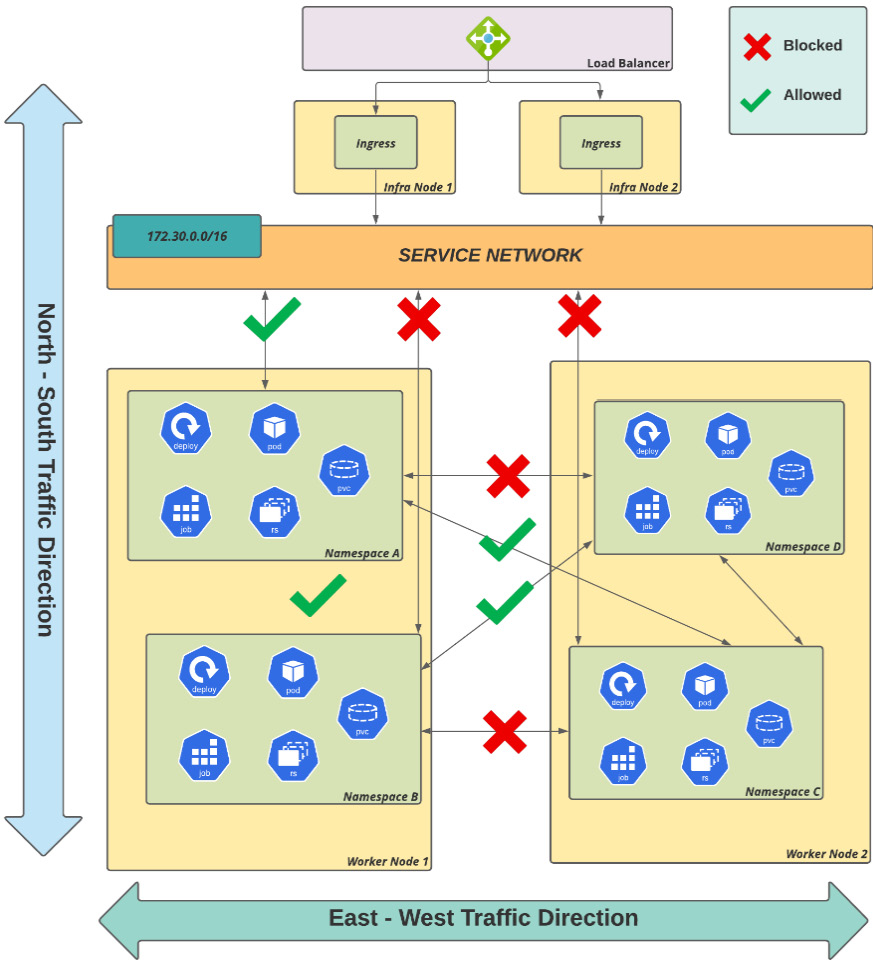
Figure 7.4 – North-south/east-west traffic flow
You have seen the possible directions in which the traffic on the network can be controlled. In the next section, you will see how to control the network traffic in the cluster.
Controlling network traffic
There are different options for controlling traffic on OpenShift:
- For north-south traffic, you can either use an external firewall and load balancer to control the traffic before getting into the OpenShift cluster or use annotations in the OpenShift route object to control aspects such as the rate limit, timeout, and load balancing algorithm.
- Use a proper network policy to allow or deny a traffic flow, as needed.
- Use the ovs-multitenant network isolation mode. This mode was commonly used on OpenShift version 3 but is not encouraged on version 4, as the Network Policy plugin has become the standard.
- If you intend to use microservices with OpenShift, you may also choose to use a service mesh to control the east-west traffic, which uses the istio-proxy sidecar to give the lowest granularity of isolation mode. Service meshes are not the focus of this book, but if you want more information on them, check out the Further reading section of this chapter.
Note
If you used to use ovs-multitenant on OpenShift 3.x and want to have similar functionality on version 4.x, we recommend you customize the project template, adding network policies to block traffic between different projects by default. The process to do that is simple and described at this link: https://docs.openshift.com/container-platform/latest/networking/network_policy/default-network-policy.html.
In this chapter, we will focus on Network Policy, as this is the standard network plugin on OpenShift 4. See next how to create a network policy to control the network traffic.
Creating a network policy
As we already mentioned, with network policies, you can define rules to allow or block ingress network traffic in a cluster. With a network policy, you can, for instance, allow traffic between pods inside the same namespace but deny it from other namespaces. You may also allow traffic only on a specific port, and so on. Therefore, for a better understanding of network policies and the directions in which traffic is and isn’t allowed to flow, we will provide several diagrams and scenarios to clarify the importance of namespace isolation.
For learning purposes, we will use three namespaces, named bluepets, greenpets, and otherpets. In the following diagram, we are illustrating the default network policy, which allows traffic between namespaces and traffic from a cluster ingress by default:
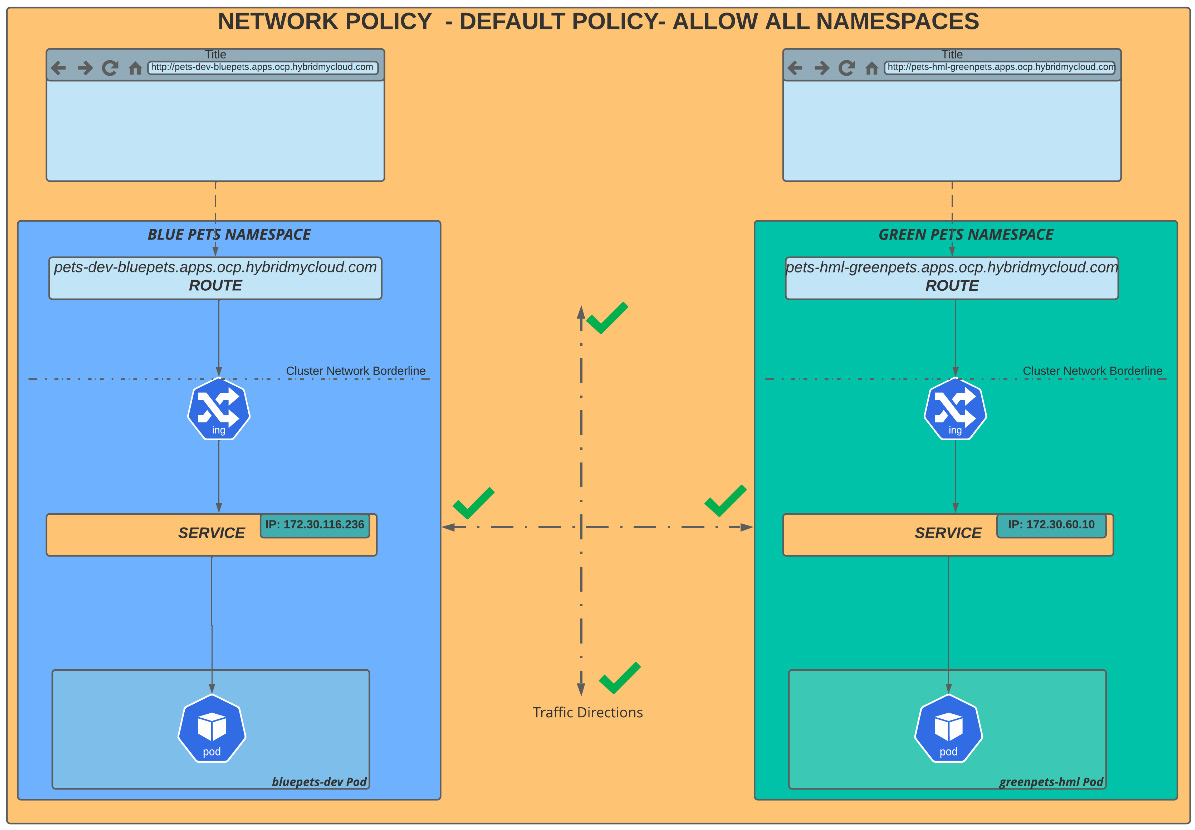
Figure 7.5 – Default network policy – allow all
So, let’s go ahead and demonstrate connections allowed to these two namespaces: bluepets and greenpets. To facilitate your understanding, we are running tests in an external network with no direct route to the service network, which is the only routable network from our cluster. So, to simulate all scenarios, we access the pod using rsh on the greenpets namespace and try to reach the service IP of the bluepets namespace in our lab scenario discussed previously.
Before going into that, we must get the service IPs from both the namespaces to use later in the pod terminal and check the results accordingly.
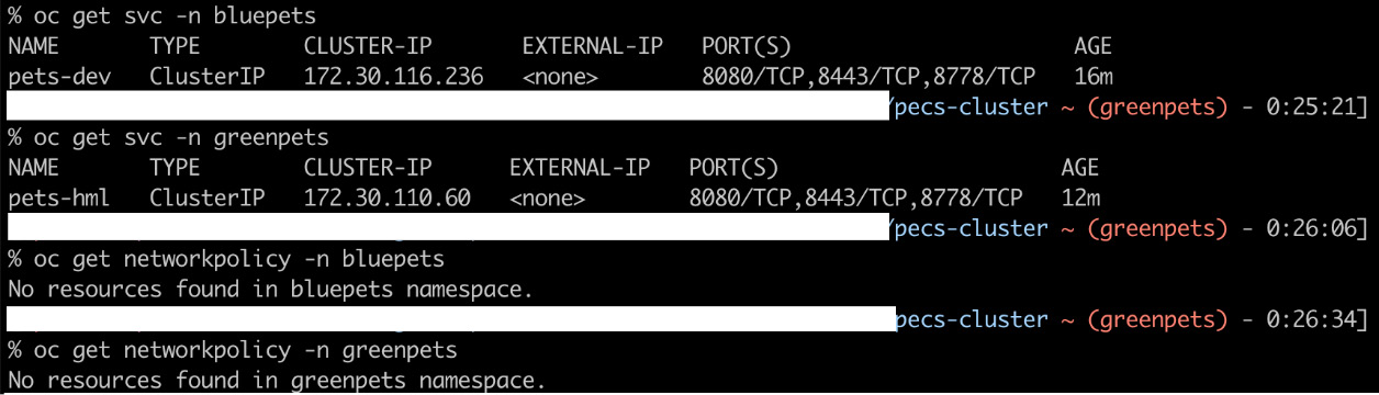
Figure 7.6 – Service IPs – bluepets and greenpets namespaces
Take a look at the following screenshot. We rsh a pod under the greenpets namespace and run curl on the following endpoints:
- The service IP in greenpets (the same namespace): To check connectivity between a pod and service in the same namespace (highlighted with a green square in the following screenshot).
- The service IP in bluepets (a different namespace): We similarly call the service IP of the bluepets namespace and it also works fine (highlighted with a blue square in the following screenshot).
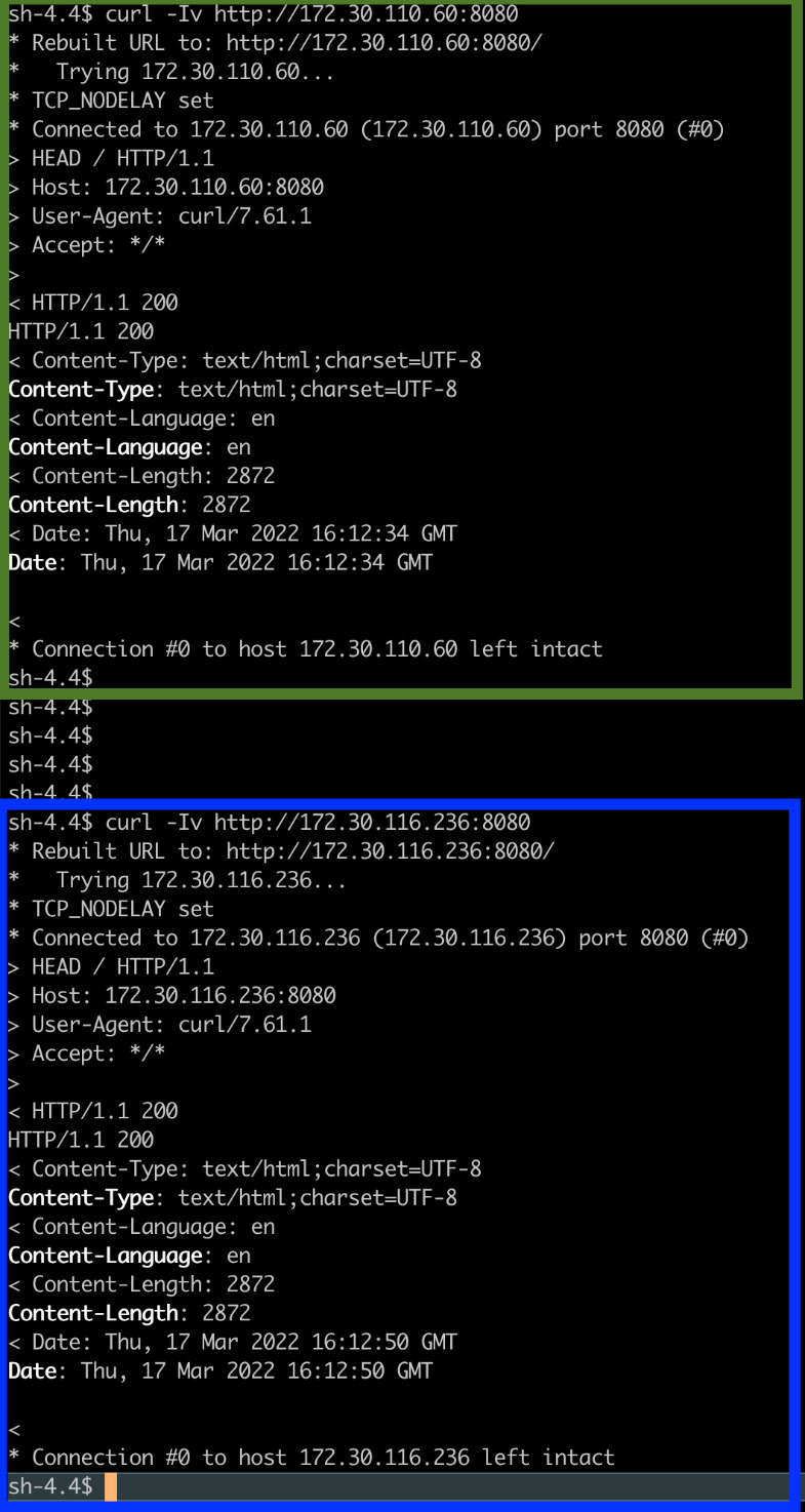
Figure 7.7 – Testing connectivity between two namespaces
In our next scenario, we will block all traffic on the greenpets namespace, for which the diagram looks like the following:
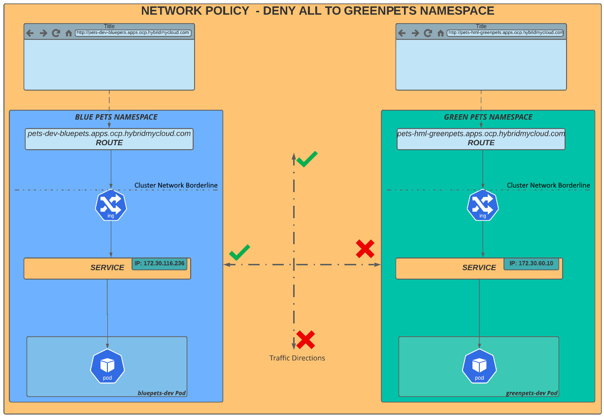
Figure 7.8 – greenpets namespace – denying all traffic
To accomplish this scenario, we apply a network policy manifest on the greenpets namespace:
$ cat << EOF >> block-everything-to-namespace.yaml
kind: NetworkPolicy
apiVersion: networking.k8s.io/v1
metadata:
  name: deny-by-default
spec:
  podSelector:
  ingress: []
EOF
$ oc –n greenpets apply –f block-everything-to-namespace.yaml
Now, let’s perform the same tests again to demonstrate that all network traffic in greenpets (route and service) is denying connections:
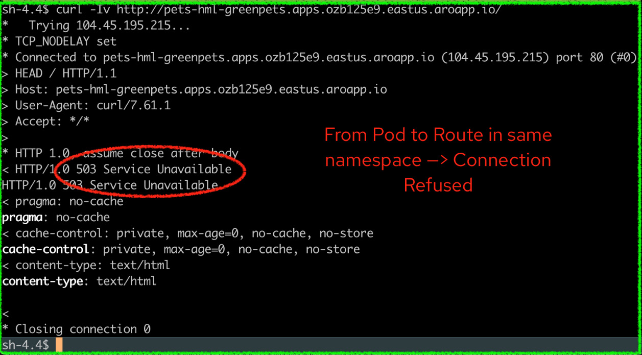
Figure 7.9 – Deny all traffic test
Now, we will go deeper and apply a rule that only allows traffic from ingress to flow to pods under the greenpets namespace. To do so, we are going to apply the following YAML file:
$ cat << EOF >>allow-ingress-to-namespace.yaml
apiVersion: networking.k8s.io/v1
kind: NetworkPolicy
metadata:
  name: allow-from-openshift-ingress
spec:
  ingress:
  - from:
    - namespaceSelector:
        matchLabels:
          network.openshift.io/policy-group: ingress
  podSelector: {}
  policyTypes:
  - Ingress
EOF
$ oc –n greenpets  apply –f allow-ingress-to-namespace.yaml
What this NP does is to only allow pods in the ingress namespace to communicate with pods in the greenpets namespace, all other traffic will be blocked. Check out the following diagram and notice that east-west traffic between namespaces is denied, but north-south traffic is allowed:
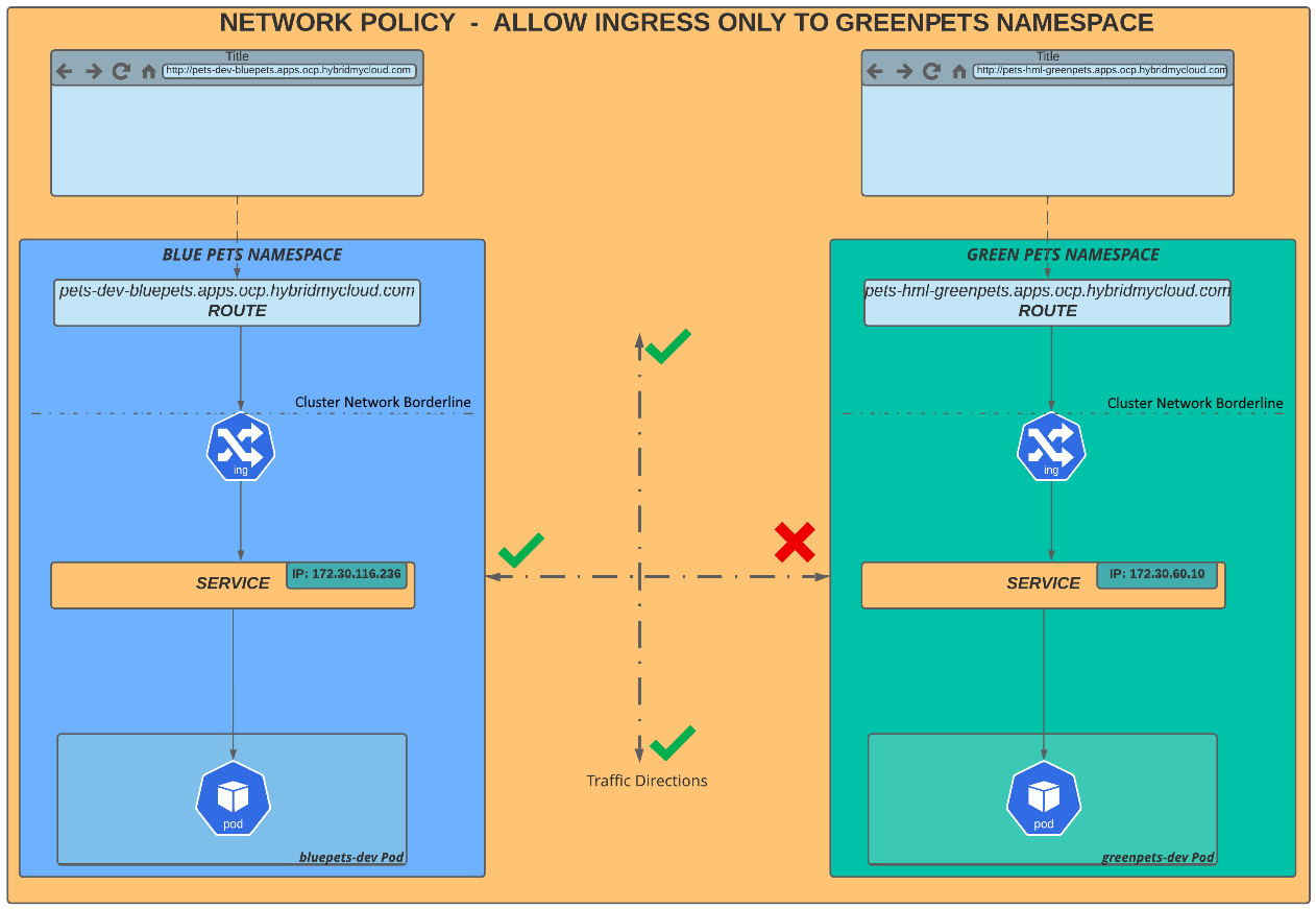
Figure 7.10 – greenpets namespace traffic only allowed for Ingress connections (external route)
Notice now that the network communication between the external route (ingress) and the service is working; however, traffic between bluepets and greenpets is denied.
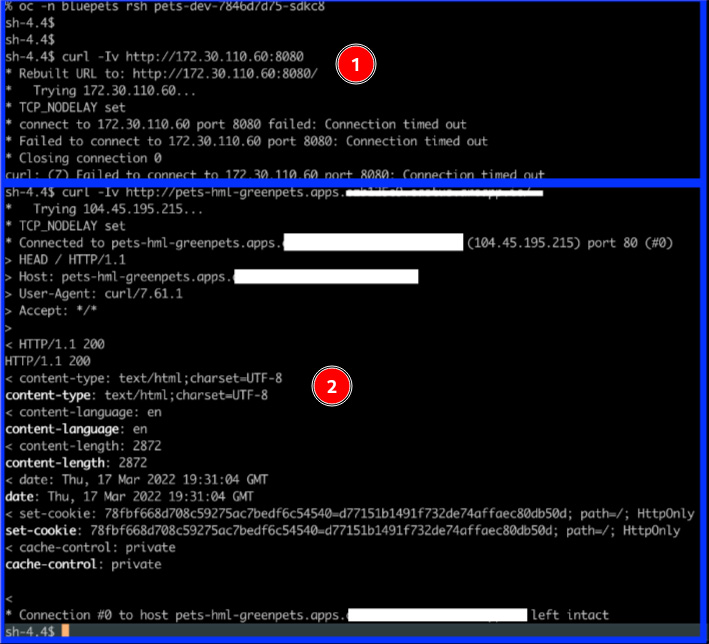
Figure 7.11 – Testing network traffic. 1) From bluepets namespace to greenpets namespace: Connection denied. 2) From external route (ingress) to greenpets namespace: Connection allowed.
Finally, we will take a look at the most common scenario: the least isolation configuration. This network policy scenario is based on a namespace label that we will apply in the greenpets namespace and will work as a key to configure the communication between namespaces.
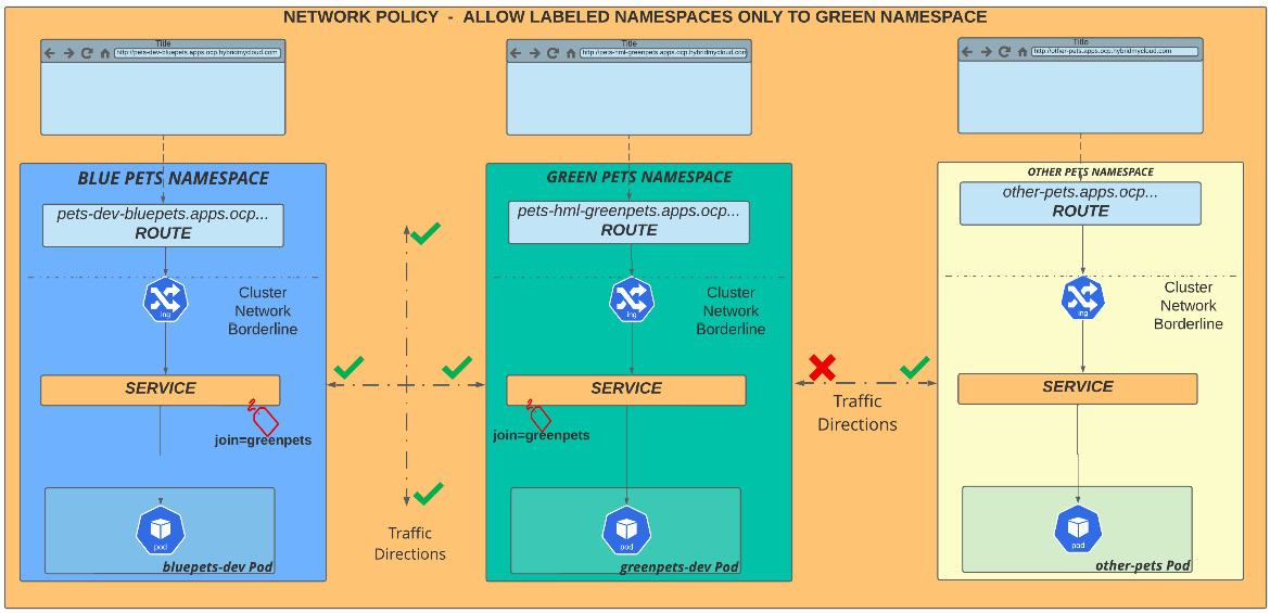
Figure 7.12 – Labeled namespaces allowing traffic
Looking at the previous diagram, you can see three different namespaces, bluepets, greenpets, and otherpets. A network policy will be applied to the greenpets namespace, which will use a label with the join=greenpets value. In other words, it means that only elements in namespaces labeled with join=greenpets can communicate with the application in the greenpets namespace. To implement this, we will apply the following manifest and commands:
$ cat << EOF >> allow-namespace-by-label.yaml
apiVersion: networking.k8s.io/v1
kind: NetworkPolicy
metadata:
  name: allow-from-namespace-label
spec:
  ingress:
  - from:
    - namespaceSelector:
        matchLabels:
          join: greenpets
  podSelector: {}
EOF
$ oc –n greenpets apply –f allow-namespace-by-label.yaml
$ oc label namespace bluepets join=greenpets
Now, check the connectivity between the namespaces bluepets and greenpets by running the following test:
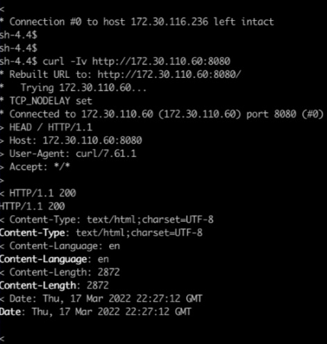
Figure 7.13 – Testing labeled namespace. Connection to a namespace that contains the proper label – connection allowed
In Figure 7.13, you see that the connection was allowed as the namespace contains the label join=greenpets. However, in Figure 7.14, you can see the connection is denied, as the traffic flows from a namespace (otherpets) that doesn’t contain this label.
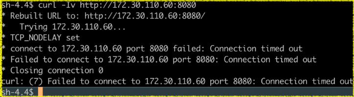
Figure 7.14 – Testing non-labeled namespace denying traffic
Network policy is an important tool to isolate network traffic. It is important you consider the challenges that certain types of rules may bring, though. If not properly designed, standardized, and adopted, they may cause you headaches by allowing what should be blocked and blocking what shouldn’t be.
Also, you have to consider which types of workload will run in your cluster. For microservice-oriented applications, for instance, we recommend you look at the Istio service mesh, which in general is more appropriate and will bring more granular network access control.
So far, you have learned the definitions and important concepts of SDNs, such as controlling traffic in horizontal and vertical directions by applying policies using labels. Continue, next, to see more about routes and ingress controllers and learn how to use them for your applications.
What is an ingress controller?
An Ingress controller is a lightweight, self-healing load balancer that distributes network traffic from outside the cluster to a network service. Using an Ingress controller is a standard approach for providing and managing ingress traffic to containerized applications. The default ingress controllers on OpenShift use the mature and stable HAProxy under the hood. In OpenShift, when you deploy a cluster, the ingress controller is automatically created and hosted in two worker nodes by default.
How does an ingress operator work?
An Ingress operator acts similarly to almost all cluster operators in OpenShift: protecting the important settings of the operation of a cluster. The operator monitors the ingress pods running in the openshift-ingress namespace and protects the IngressController objects from wrong and non-compatible settings that can lead to problems with the cluster network.
Otherwise, you can create others IngressController objects in addition to the default one to isolate the traffic of certain groups of applications, using what is named router sharding.
Different from traditional networking configuration, in which you need complex routing tables and firewall configuration, OpenShift abstracts this complex networking layer configuration, making it a much easier task.
Creating a new ingress controller
To create a new ingress controller, you must take the following steps:
- Define at least two nodes to host the new ingress controller.
- Apply a new label to nodes.
- Export the default IngressController object.
- Change the name and desired settings of the newly created YAML manifest file.
- Deploy the new IngressController object by applying the YAML created previously.
You can see in the following lines an example of the process mentioned previously:
# Apply labels to nodes
$ oc label node <node1> <node2> .. <nodeN> new-ingress=true
$ oc get ingresscontroller default -n openshift-ingress-operator -o yaml > new-ingress.yaml
$ vi new-ingress.yaml
# Remove unnecessary fields to make the yaml looks like
# the following one
apiVersion: operator.openshift.io/v1
kind: IngressController
metadata:
  name: new-ingress [1]
  namespace: openshift-ingress-operator
spec:
  domain: apps.env.hybridmycloud.com [2]
  replicas: 2
  nodePlacement:
    nodeSelector:
      matchLabels:
        new-ingress: "true" [3]
  routeSelector: [4]
    matchLabels:
      type: sharded [5]
In the previous code, we have highlighted some parts with numbers. Let’s take a look:
[1]: New IngressController name.
[2]: DNS domain for the new ingress.
[3]: A label that defines where the IngressController pods will run.
[4]: To implement shards. It can be namespaceSelector or routeSelector.
[5]: Used to filter the set of routes that are served by this IngressController.
Namespace or Route Selector?
The example you have seen uses the routeSelector. There is an alternative way to configure the IngressController, which is using namespaceSelector. It may seem confusing to define the right selector for your case, but it is not – routeSelector is a more granular option, allowing you to publish routes to different IngressControllers in the same namespace. The main decision factor is if, in your case, you need to be able to publish routes of a single namespace in different IngressControllers, you have to use routeSelectors. Otherwise, you will most likely use namespaceSelectors.
For example, consider a namespace called APP that contains two different routes:
Route A published in router 1 with the URL app1.prod.hybridmycloud.com
Route B published in router 2 with the URL app1.qa.hybridmycloud.com
This scenario is only possible if you use routeSelector. However, this is an unusual scenario; usually, routes in a single namespace are always published in the same IngressController, so for that reason, it is also very common to use namespaceSelector.
As previously mentioned, router sharding is a technique that allows creating an ingress for the purpose of segregating traffic, whether due to the need for isolation between environments or even for the traffic of a given application to be fully directed from this new ingress.
Testing the new ingress
After the ingress pods are created on the nodes, you can test the newly created ingress. We will create a route using the sample application named hello-openshift and apply the proper route selector label. Follow these steps to accomplish this task:
$ oc new-project hello-openshift
$ oc create -f https://raw.githubusercontent.com/openshift/origin/master/examples/hello-openshift/hello-pod.json
$ oc expose pod/hello-openshift
$ oc expose svc hello-openshift
$ oc label route hello-openshift type=sharded
The last line of the previous block of commands explicitly sets the type=sharded label, which we used in our example for routeSelector. When OpenShift sees this label, it will automatically publish this route in the new ingress.
Continue on to the following section to get a full understanding of how to use the recently created ingress with what is called a route in OpenShift.
Types of routes
Routes are the representation of a configuration on an ingress internal load balancer for a specific application to expose a Kubernetes service to a DNS name, such as example.apps.env.hybridmycloud.com. When a route is created, OpenShift automatically configures a frontend and backend in the Ingress’ HAProxy pod to publish the URL and make the traffic available from the outside world.
Routes can be published using either the HTTP or HTTPS protocol. For HTTPS, three different types of routes define how the TLS termination works in the SSL stream between the user and the pod. In the following subsections, we will walk you through each of them.
Passthrough routes
A passthrough route, as the name suggests, is a configuration in which the packages are forwarded straight to the network service without doing a TLS termination, acting as a Layer 4 load balancer. Passthrough is often used with applications that provide their own TLS termination inside the application’s pod, either by implementing it in the source code or using a middleware layer (such as JBoss or WebSphere).
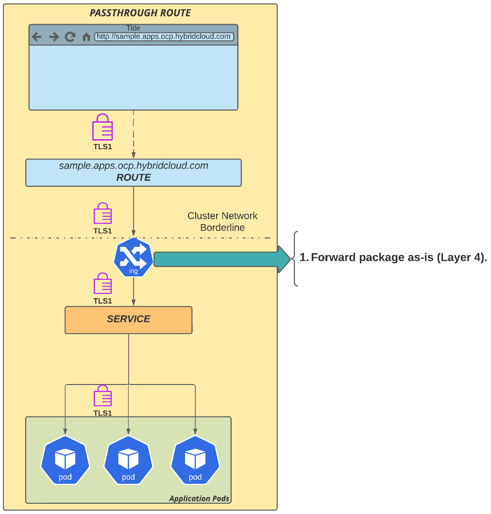
Figure 7.15 – Passthrough route
Next, you'll see the second option you have: edge route.
Edge routes
In this route, the TLS termination is handled by OpenShift ingress and forwarded to the service as clear text. This kind of route is used very often as it is easy to use: a self-signed certificate automatically generated by OpenShift is applied to the ingress and it signs all the routes that use the default wildcard domain – this is performed by OpenShift automatically; no additional configuration is needed. However, you can replace the self-signed certificate with a custom digital certificate, if you don’t want to use the default self-signed certificate.
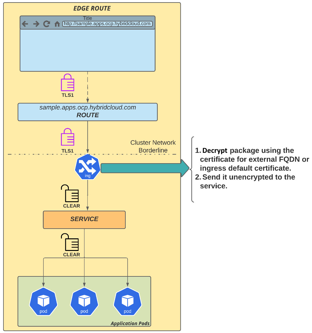
Figure 7.16 – Edge route
An edge route is the most common and easy-to-implement model since the certificate chain terminates at the edge of the OpenShift network, which is the ingress. It is important to highlight that the traffic between the ingress and the application pods is not encrypted but occurs inside the OpenShift SDN, which means that the network packages are encapsulated using OVS. The last method available is reencrypted routes. You'll see how it works next.
Reencrypted routes
Reencrypted routes offer two layers of TLS termination: traffic is decrypted using the certificate for the external FQDN (for example, example.apps.env.hybridmycloud.com) at the cluster edge (OpenShift Ingress), and then the traffic is re-encrypted again, but now using a different certificate. While this is a secure route, it has also a performance penalty due to the termination and re-encryption operation performed by the ingress.
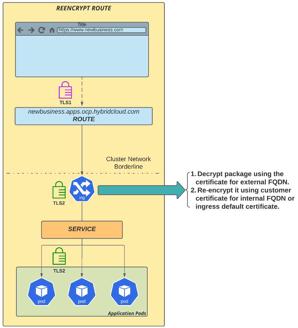
Figure 7.17 – Reencrypted route
A reencrypted route takes a similar approach as an edge route but it goes through two layers of CAs. The first is related to the external public domain, for example, hybridcloud.com, and then the second layer of encryption is internal, known by OpenShift Ingress and the application.
Summary
We have seen in this chapter some of the important aspects related to the OpenShift network. Now you are familiar with the two types of network plugins supported with OpenShift, OpenShift SDN and OVN-Kubernetes, and the different kinds of traffic you need to care about when managing the platform’s network. You have also seen how the ingress controller works, how to create a new one, and the three different types of secure routes you may use with your applications: passthrough, edge, and reencrypted.
You navigated through network policies to learn a bit more about how to control traffic and provide network isolation.
As you know, security is a real concern in today's digital world. In the next chapter, we will cover important aspects you need to consider about security on OpenShift. So, go ahead and check it out!
Further reading
If you want more information related to the concepts we covered in this chapter, check out the following references:
- Kubernetes Ingress controller: https://www.nginx.com/resources/glossary/kubernetes-ingress-controller
- HAProxy documentation: https://www.haproxy.com/documentation/hapee/latest/onepage/
- Annotations used to override a route’s default configuration: https://docs.openshift.com/container-platform/4.10/networking/routes/route-configuration.html#nw-route-specific-annotations_route-configuration
- Configuring ingress cluster traffic using an Ingress controller: https://docs.openshift.com/container-platform/4.10/networking/configuring_ingress_cluster_traffic/configuring-ingress-cluster-traffic-ingress-controller.html
- Creating secured routes: https://docs.openshift.com/container-platform/4.10/networking/routes/secured-routes.html
- OpenShift Tested Integrations: https://access.redhat.com/articles/4128421
- Service mesh: https://docs.openshift.com/container-platform/4.10/service_mesh/v2x/servicemesh-release-notes.html