
CHAPTER 13
I/O Systems
The two main jobs of a computer are I/O and processing. In many cases, the main job is I/O, and the processing is merely incidental. For instance, when we browse a web page or edit a file, our immediate interest is to read or enter some information, not to compute an answer.
The role of the operating system in computer I/O is to manage and control I/O operations and I/O devices. Although related topics appear in other chapters, here we bring together the pieces to paint a complete picture of I/O. First, we describe the basics of I/O hardware, because the nature of the hardware interface places constraints on the internal facilities of the operating system. Next, we discuss the I/O services provided by the operating system and the embodiment of these services in the application I/O interface. Then, we explain how the operating system bridges the gap between the hardware interface and the application interface. We also discuss the UNIX System V STREAMS mechanism, which enables an application to assemble pipelines of driver code dynamically. Finally, we discuss the performance aspects of I/O and the principles of operating-system design that improve I/O performance.
CHAPTER OBJECTIVES
- To explore the structure of an operating system's I/O subsystem.
- To discuss the principles and complexities of I/O hardware.
- To explain the performance aspects of I/O hardware and software.
13.1 Overview
The control of devices connected to the computer is a major concern of operating-system designers. Because I/O devices vary so widely in their function and speed (consider a mouse, a hard disk, and a tape robot), varied methods are needed to control them. These methods form the I/O subsystem of the kernel, which separates the rest of the kernel from the complexities of managing I/O devices.
I/O-device technology exhibits two conflicting trends. On the one hand, we see increasing standardization of software and hardware interfaces. This trend helps us to incorporate improved device generations into existing computers and operating systems. On the other hand, we see an increasingly broad variety of I/O devices. Some new devices are so unlike previous devices that it is a challenge to incorporate them into our computers and operating systems. This challenge is met by a combination of hardware and software techniques. The basic I/O hardware elements, such as ports, buses, and device controllers, accommodate a wide variety of I/O devices. To encapsulate the details and oddities of different devices, the kernel of an operating system is structured to use device-driver modules. The device drivers present a uniform device-access interface to the I/O subsystem, much as system calls provide a standard interface between the application and the operating system.
13.2 I/O Hardware
Computers operate a great many kinds of devices. Most fit into the general categories of storage devices (disks, tapes), transmission devices (network connections, Bluetooth), and human-interface devices (screen, keyboard, mouse, audio in and out). Other devices are more specialized, such as those involved in the steering of a jet. In these aircraft, a human gives input to the flight computer via a joystick and foot pedals, and the computer sends output commands that cause motors to move rudders and flaps and fuels to the engines. Despite the incredible variety of I/O devices, though, we need only a few concepts to understand how the devices are attached and how the software can control the hardware.
A device communicates with a computer system by sending signals over a cable or even through the air. The device communicates with the machine via a connection point, or port—for example, a serial port. If devices share a common set of wires, the connection is called a bus. A bus is a set of wires and a rigidly defined protocol that specifies a set of messages that can be sent on the wires. In terms of the electronics, the messages are conveyed by patterns of electrical voltages applied to the wires with defined timings. When device A has a cable that plugs into device B, and device B has a cable that plugs into device C, and device C plugs into a port on the computer, this arrangement is called a daisy chain. A daisy chain usually operates as a bus.
Buses are used widely in computer architecture and vary in their signaling methods, speed, throughput, and connection methods. A typical PC bus structure appears in Figure 13.1. In the figure, a PCI bus (the common PC system bus) connects the processor–memory subsystem to fast devices, and an expansion bus connects relatively slow devices, such as the keyboard and serial and USB ports. In the upper-right portion of the figure, four disks are connected together on a Small Computer System Interface (SCSI) bus plugged into a SCSI controller. Other common buses used to interconnect main parts of a computer include PCI Express (PCIe), with throughput of up to 16 GB per second, and HyperTransport, with throughput of up to 25 GB per second.
A controller is a collection of electronics that can operate a port, a bus, or a device. A serial-port controller is a simple device controller. It is a single chip (or portion of a chip) in the computer that controls the signals on the wires of a serial port. By contrast, a SCSI bus controller is not simple. Because the SCSI protocol is complex, the SCSI bus controller is often implemented as a separate circuit board (or a host adapter) that plugs into the computer. It typically contains a processor, microcode, and some private memory to enable it to process the SCSI protocol messages. Some devices have their own built-in controllers. If you look at a disk drive, you will see a circuit board attached to one side. This board is the disk controller. It implements the disk side of the protocol for some kind of connection—SCSI or Serial Advanced Technology Attachment (SATA), for instance. It has microcode and a processor to do many tasks, such as bad-sector mapping, prefetching, buffering, and caching.

Figure 13.1 A typical PC bus structure.
How can the processor give commands and data to a controller to accomplish an I/O transfer? The short answer is that the controller has one or more registers for data and control signals. The processor communicates with the controller by reading and writing bit patterns in these registers. One way in which this communication can occur is through the use of special I/O instructions that specify the transfer of a byte or word to an I/O port address. The I/O instruction triggers bus lines to select the proper device and to move bits into or out of a device register. Alternatively, the device controller can support memory-mapped I/O. In this case, the device-control registers are mapped into the address space of the processor. The CPU executes I/O requests using the standard data-transfer instructions to read and write the device-control registers at their mapped locations in physical memory.
Some systems use both techniques. For instance, PCs use I/O instructions to control some devices and memory-mapped I/O to control others. Figure 13.2 shows the usual I/O port addresses for PCs. The graphics controller has I/O ports for basic control operations, but the controller has a large memory-mapped region to hold screen contents. The process sends output to the screen by writing data into the memory-mapped region. The controller generates the screen image based on the contents of this memory. This technique is simple to use. Moreover, writing millions of bytes to the graphics memory is faster than issuing millions of I/O instructions. But the ease of writing to a memory-mapped I/O controller is offset by a disadvantage. Because a common type of software fault is a write through an incorrect pointer to an unintended region of memory, a memory-mapped device register is vulnerable to accidental modification. Of course, protected memory helps to reduce this risk.

Figure 13.2 Device I/O port locations on PCs (partial).
An I/O port typically consists of four registers, called the status, control, data-in, and data-out registers.
- The data-in register is read by the host to get input.
- The data-out register is written by the host to send output.
- The status register contains bits that can be read by the host. These bits indicate states, such as whether the current command has completed, whether a byte is available to be read from the data-in register, and whether a device error has occurred.
- The control register can be written by the host to start a command or to change the mode of a device. For instance, a certain bit in the control register of a serial port chooses between full-duplex and half-duplex communication, another bit enables parity checking, a third bit sets the word length to 7 or 8 bits, and other bits select one of the speeds supported by the serial port.
The data registers are typically 1 to 4 bytes in size. Some controllers have FIFO chips that can hold several bytes of input or output data to expand the capacity of the controller beyond the size of the data register. A FIFO chip can hold a small burst of data until the device or host is able to receive those data.
13.2.1 Polling
The complete protocol for interaction between the host and a controller can be intricate, but the basic handshaking notion is simple. We explain handshaking with an example. Assume that 2 bits are used to coordinate the producer–consumer relationship between the controller and the host. The controller indicates its state through the busy bit in the status register. (Recall that to set a bit means to write a 1 into the bit and to clear a bit means to write a 0 into it.) The controller sets the busy bit when it is busy working and clears the busy bit when it is ready to accept the next command. The host signals its wishes via the command-ready bit in the command register. The host sets the command-ready bit when a command is available for the controller to execute. For this example, the host writes output through a port, coordinating with the controller by handshaking as follows.
- The host repeatedly reads the busy bit until that bit becomes clear.
- The host sets the write bit in the command register and writes a byte into the data-out register.
- The host sets the command-ready bit.
- When the controller notices that the command-ready bit is set, it sets the busy bit.
- The controller reads the command register and sees the write command. It reads the data-out register to get the byte and does the I/O to the device.
- The controller clears the command-ready bit, clears the error bit in the status register to indicate that the device I/O succeeded, and clears the busy bit to indicate that it is finished.
This loop is repeated for each byte.
In step 1, the host is busy-waiting or polling: it is in a loop, reading the status register over and over until the busy bit becomes clear. If the controller and device are fast, this method is a reasonable one. But if the wait may be long, the host should probably switch to another task. How, then, does the host know when the controller has become idle? For some devices, the host must service the device quickly, or data will be lost. For instance, when data are streaming in on a serial port or from a keyboard, the small buffer on the controller will overflow and data will be lost if the host waits too long before returning to read the bytes.
In many computer architectures, three CPU-instruction cycles are sufficient to poll a device: read a device register, logical--and to extract a status bit, and branch if not zero. Clearly, the basic polling operation is efficient. But polling becomes inefficient when it is attempted repeatedly yet rarely finds a device ready for service, while other useful CPU processing remains undone. In such instances, it may be more efficient to arrange for the hardware controller to notify the CPU when the device becomes ready for service, rather than to require the CPU to poll repeatedly for an I/O completion. The hardware mechanism that enables a device to notify the CPU is called an interrupt.

Figure 13.3 Interrupt-driven I/O cycle.
13.2.2 Interrupts
The basic interrupt mechanism works as follows. The CPU hardware has a wire called the interrupt-request line that the CPU senses after executing every instruction. When the CPU detects that a controller has asserted a signal on the interrupt-request line, the CPU performs a state save and jumps to the interrupt-handler routine at a fixed address in memory. The interrupt handler determines the cause of the interrupt, performs the necessary processing, performs a state restore, and executes a return from interrupt instruction to return the CPU to the execution state prior to the interrupt. We say that the device controller raises an interrupt by asserting a signal on the interrupt request line, the CPU catches the interrupt and dispatches it to the interrupt handler, and the handler clears the interrupt by servicing the device. Figure 13.3 summarizes the interrupt-driven I/O cycle. We stress interrupt management in this chapter because even single-user modern systems manage hundreds of interrupts per second and servers hundreds of thousands per second.
The basic interrupt mechanism just described enables the CPU to respond to an asynchronous event, as when a device controller becomes ready for service. In a modern operating system, however, we need more sophisticated interrupt-handling features.
- We need the ability to defer interrupt handling during critical processing.
- We need an efficient way to dispatch to the proper interrupt handler for a device without first polling all the devices to see which one raised the interrupt.
- We need multilevel interrupts, so that the operating system can distinguish between high- and low-priority interrupts and can respond with the appropriate degree of urgency.
In modern computer hardware, these three features are provided by the CPU and by the interrupt-controller hardware.
Most CPUs have two interrupt request lines. One is the nonmaskable interrupt, which is reserved for events such as unrecoverable memory errors. The second interrupt line is maskable: it can be turned off by the CPU before the execution of critical instruction sequences that must not be interrupted. The maskable interrupt is used by device controllers to request service.
The interrupt mechanism accepts an address—a number that selects a specific interrupt-handling routine from a small set. In most architectures, this address is an offset in a table called the interrupt vector. This vector contains the memory addresses of specialized interrupt handlers. The purpose of a vectored interrupt mechanism is to reduce the need for a single interrupt handler to search all possible sources of interrupts to determine which one needs service. In practice, however, computers have more devices (and, hence, interrupt handlers) than they have address elements in the interrupt vector. A common way to solve this problem is to use interrupt chaining, in which each element in the interrupt vector points to the head of a list of interrupt handlers. When an interrupt is raised, the handlers on the corresponding list are called one by one, until one is found that can service the request. This structure is a compromise between the overhead of a huge interrupt table and the inefficiency of dispatching to a single interrupt handler.
Figure 13.4 illustrates the design of the interrupt vector for the Intel Pentium processor. The events from 0 to 31, which are nonmaskable, are used to signal various error conditions. The events from 32 to 255, which are maskable, are used for purposes such as device-generated interrupts.
The interrupt mechanism also implements a system of interrupt priority levels. These levels enable the CPU to defer the handling of low-priority interrupts without masking all interrupts and makes it possible for a high-priority interrupt to preempt the execution of a low-priority interrupt.
A modern operating system interacts with the interrupt mechanism in several ways. At boot time, the operating system probes the hardware buses to determine what devices are present and installs the corresponding interrupt handlers into the interrupt vector. During I/O, the various device controllers raise interrupts when they are ready for service. These interrupts signify that output has completed, or that input data are available, or that a failure has been detected. The interrupt mechanism is also used to handle a wide variety of exceptions, such as dividing by 0, accessing a protected or nonexistent memory address, or attempting to execute a privileged instruction from user mode. The events that trigger interrupts have a common property: they are occurrences that induce the operating system to execute an urgent, self-contained routine.
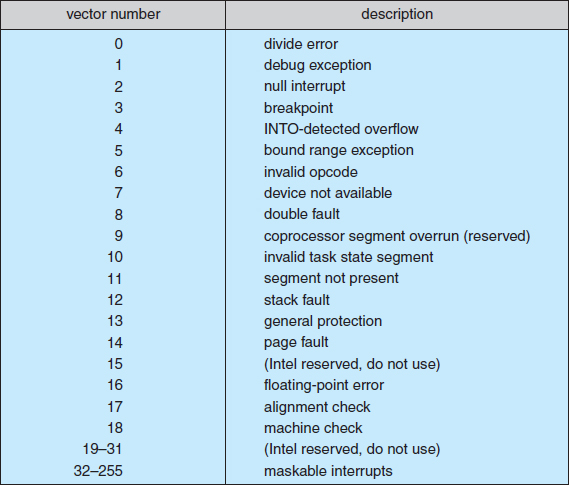
Figure 13.4 Intel Pentium processor event-vector table.
An operating system has other good uses for an efficient hardware and software mechanism that saves a small amount of processor state and then calls a privileged routine in the kernel. For example, many operating systems use the interrupt mechanism for virtual memory paging. A page fault is an exception that raises an interrupt. The interrupt suspends the current process and jumps to the page-fault handler in the kernel. This handler saves the state of the process, moves the process to the wait queue, performs page-cache management, schedules an I/O operation to fetch the page, schedules another process to resume execution, and then returns from the interrupt.
Another example is found in the implementation of system calls. Usually, a program uses library calls to issue system calls. The library routines check the arguments given by the application, build a data structure to convey the arguments to the kernel, and then execute a special instruction called a software interrupt, or trap. This instruction has an operand that identifies the desired kernel service. When a process executes the trap instruction, the interrupt hardware saves the state of the user code, switches to kernel mode, and dispatches to the kernel routine that implements the requested service. The trap is given a relatively low interrupt priority compared with those assigned to device interrupts—executing a system call on behalf of an application is less urgent than servicing a device controller before its FIFO queue overflows and loses data.
Interrupts can also be used to manage the flow of control within the kernel. For example, consider one example of the processing required to complete a disk read. One step is to copy data from kernel space to the user buffer. This copying is time consuming but not urgent—it should not block other high-priority interrupt handling. Another step is to start the next pending I/O for that disk drive. This step has higher priority. If the disks are to be used efficiently, we need to start the next I/O as soon as the previous one completes. Consequently, a pair of interrupt handlers implements the kernel code that completes a disk read. The high-priority handler records the I/O status, clears the device interrupt, starts the next pending I/O, and raises a low-priority interrupt to complete the work. Later, when the CPU is not occupied with high-priority work, the low-priority interrupt will be dispatched. The corresponding handler completes the user-level I/O by copying data from kernel buffers to the application space and then calling the scheduler to place the application on the ready queue.
A threaded kernel architecture is well suited to implement multiple interrupt priorities and to enforce the precedence of interrupt handling over background processing in kernel and application routines. We illustrate this point with the Solaris kernel. In Solaris, interrupt handlers are executed as kernel threads. A range of high priorities is reserved for these threads. These priorities give interrupt handlers precedence over application code and kernel housekeeping and implement the priority relationships among interrupt handlers. The priorities cause the Solaris thread scheduler to preempt low-priority interrupt handlers in favor of higher-priority ones, and the threaded implementation enables multiprocessor hardware to run several interrupt handlers concurrently. We describe the interrupt architecture of Windows XP and UNIX in Chapter 19 and Appendix A, respectively.
In summary, interrupts are used throughout modern operating systems to handle asynchronous events and to trap to supervisor-mode routines in the kernel. To enable the most urgent work to be done first, modern computers use a system of interrupt priorities. Device controllers, hardware faults, and system calls all raise interrupts to trigger kernel routines. Because interrupts are used so heavily for time-sensitive processing, efficient interrupt handling is required for good system performance.
13.2.3 Direct Memory Access
For a device that does large transfers, such as a disk drive, it seems wasteful to use an expensive general-purpose processor to watch status bits and to feed data into a controller register one byte at a time—a process termed programmed I/O (PIO). Many computers avoid burdening the main CPU with PIO by offloading some of this work to a special-purpose processor called a direct-memory-access (DMA) controller. To initiate a DMA transfer, the host writes a DMA command block into memory. This block contains a pointer to the source of a transfer, a pointer to the destination of the transfer, and a count of the number of bytes to be transferred. The CPU writes the address of this command block to the DMA controller, then goes on with other work. The DMA controller proceeds to operate the memory bus directly, placing addresses on the bus to perform transfers without the help of the main CPU. A simple DMA controller is a standard component in all modern computers, from smartphones to mainframes.
Handshaking between the DMA controller and the device controller is performed via a pair of wires called DMA-request and DMA-acknowledge. The device controller places a signal on the DMA-request wire when a word of data is available for transfer. This signal causes the DMA controller to seize the memory bus, place the desired address on the memory-address wires, and place a signal on the DMA-acknowledge wire. When the device controller receives the DMA-acknowledge signal, it transfers the word of data to memory and removes the DMA-request signal.
When the entire transfer is finished, the DMA controller interrupts the CPU. This process is depicted in Figure 13.5. When the DMA controller seizes the memory bus, the CPU is momentarily prevented from accessing main memory, although it can still access data items in its primary and secondary caches. Although this cycle stealing can slow down the CPU computation, offloading the data-transfer work to a DMA controller generally improves the total system performance. Some computer architectures use physical memory addresses for DMA, but others perform direct virtual memory access (DVMA), using virtual addresses that undergo translation to physical addresses. DVMA can perform a transfer between two memory-mapped devices without the intervention of the CPU or the use of main memory.
On protected-mode kernels, the operating system generally prevents processes from issuing device commands directly. This discipline protects data from access-control violations and also protects the system from erroneous use of device controllers that could cause a system crash. Instead, the operating system exports functions that a sufficiently privileged process can use to access low-level operations on the underlying hardware. On kernels without memory protection, processes can access device controllers directly. This direct access can be used to achieve high performance, since it can avoid kernel communication, context switches, and layers of kernel software. Unfortunately, it interferes with system security and stability. The trend in general-purpose operating systems is to protect memory and devices so that the system can try to guard against erroneous or malicious applications.
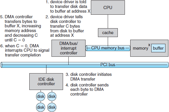
Figure 13.5 Steps in a DMA transfer.
13.2.4 I/O Hardware Summary
Although the hardware aspects of I/O are complex when considered at the level of detail of electronics-hardware design, the concepts that we have just described are sufficient to enable us to understand many I/O features of operating systems. Let's review the main concepts:
- A bus
- A controller
- An I/O port and its registers
- The handshaking relationship between the host and a device controller
- The execution of this handshaking in a polling loop or via interrupts
- The offloading of this work to a DMA controller for large transfers
We gave a basic example of the handshaking that takes place between a device controller and the host earlier in this section. In reality, the wide variety of available devices poses a problem for operating-system implementers. Each kind of device has its own set of capabilities, control-bit definitions, and protocols for interacting with the host—and they are all different. How can the operating system be designed so that we can attach new devices to the computer without rewriting the operating system? And when the devices vary so widely, how can the operating system give a convenient, uniform I/O interface to applications? We address those questions next.
13.3 Application I/O Interface
In this section, we discuss structuring techniques and interfaces for the operating system that enable I/O devices to be treated in a standard, uniform way. We explain, for instance, how an application can open a file on a disk without knowing what kind of disk it is and how new disks and other devices can be added to a computer without disruption of the operating system.
Like other complex software-engineering problems, the approach here involves abstraction, encapsulation, and software layering. Specifically, we can abstract away the detailed differences in I/O devices by identifying a few general kinds. Each general kind is accessed through a standardized set of functions—an interface. The differences are encapsulated in kernel modules called device drivers that internally are custom-tailored to specific devices but that export one of the standard interfaces. Figure 13.6 illustrates how the I/O-related portions of the kernel are structured in software layers.
The purpose of the device-driver layer is to hide the differences among device controllers from the I/O subsystem of the kernel, much as the I/O system calls encapsulate the behavior of devices in a few generic classes that hide hardware differences from applications. Making the I/O subsystem independent of the hardware simplifies the job of the operating-system developer. It also benefits the hardware manufacturers. They either design new devices to be compatible with an existing host controller interface (such as SATA), or they write device drivers to interface the new hardware to popular operating systems. Thus, we can attach new peripherals to a computer without waiting for the operating-system vendor to develop support code.
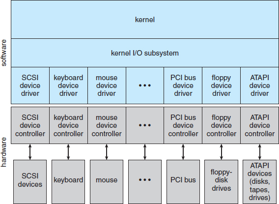
Figure 13.6 A kernel I/O structure.
Unfortunately for device-hardware manufacturers, each type of operating system has its own standards for the device-driver interface. A given device may ship with multiple device drivers—for instance, drivers for Windows, Linux, AIX, and Mac OS X. Devices vary on many dimensions, as illustrated in Figure 13.7.
- Character-stream or block. A character-stream device transfers bytes one by one, whereas a block device transfers a block of bytes as a unit.
- Sequential or random access. A sequential device transfers data in a fixed order determined by the device, whereas the user of a random-access device can instruct the device to seek to any of the available data storage locations.
- Synchronous or asynchronous. A synchronous device performs data transfers with predictable response times, in coordination with other aspects of the system. An asynchronous device exhibits irregular or unpredictable response times not coordinated with other computer events.
- Sharable or dedicated. A sharable device can be used concurrently by several processes or threads; a dedicated device cannot.
- Speed of operation. Device speeds range from a few bytes per second to a few gigabytes per second.
- Read–write, read only, or write only. Some devices perform both input and output, but others support only one data transfer direction.

For the purpose of application access, many of these differences are hidden by the operating system, and the devices are grouped into a few conventional types. The resulting styles of device access have been found to be useful and broadly applicable. Although the exact system calls may differ across operating systems, the device categories are fairly standard. The major access conventions include block I/O, character-stream I/O, memory-mapped file access, and network sockets. Operating systems also provide special system calls to access a few additional devices, such as a time-of-day clock and a timer. Some operating systems provide a set of system calls for graphical display, video, and audio devices.
Most operating systems also have an escape (or back door) that transparently passes arbitrary commands from an application to a device driver. In UNIX, this system call is ioctl() (for “I/O control”). The ioctl() system call enables an application to access any functionality that can be implemented by any device driver, without the need to invent a new system call. The ioctl() system call has three arguments. The first is a file descriptor that connects the application to the driver by referring to a hardware device managed by that driver. The second is an integer that selects one of the commands implemented in the driver. The third is a pointer to an arbitrary data structure in memory that enables the application and driver to communicate any necessary control information or data.
13.3.1 Block and Character Devices
The block-device interface captures all the aspects necessary for accessing disk drives and other block-oriented devices. The device is expected to understand commands such as read() and write(). If it is a random-access device, it is also expected to have a seek() command to specify which block to transfer next. Applications normally access such a device through a file-system interface. We can see that read(), write(), and seek() capture the essential behaviors of block-storage devices, so that applications are insulated from the low-level differences among those devices.
The operating system itself, as well as special applications such as database management systems, may prefer to access a block device as a simple linear array of blocks. This mode of access is sometimes called raw I/O. If the application performs its own buffering, then using a file system would cause extra, unneeded buffering. Likewise, if an application provides its own locking of file blocks or regions, then any operating-system locking services would be redundant at the least and contradictory at the worst. To avoid these conflicts, raw-device access passes control of the device directly to the application, letting the operating system step out of the way. Unfortunately, no operating-system services are then performed on this device. A compromise that is becoming common is for the operating system to allow a mode of operation on a file that disables buffering and locking. In the UNIX world, this is called direct I/O.
Memory-mapped file access can be layered on top of block-device drivers. Rather than offering read and write operations, a memory-mapped interface provides access to disk storage via an array of bytes in main memory. The system call that maps a file into memory returns the virtual memory address that contains a copy of the file. The actual data transfers are performed only when needed to satisfy access to the memory image. Because the transfers are handled by the same mechanism as that used for demand-paged virtual memory access, memory-mapped I/O is efficient. Memory mapping is also convenient for programmers—access to a memory-mapped file is as simple as reading from and writing to memory. Operating systems that offer virtual memory commonly use the mapping interface for kernel services. For instance, to execute a program, the operating system maps the executable into memory and then transfers control to the entry address of the executable. The mapping interface is also commonly used for kernel access to swap space on disk.
A keyboard is an example of a device that is accessed through a character-stream interface. The basic system calls in this interface enable an application to get() or put() one character. On top of this interface, libraries can be built that offer line-at-a-time access, with buffering and editing services (for example, when a user types a backspace, the preceding character is removed from the input stream). This style of access is convenient for input devices such as keyboards, mice, and modems that produce data for input “spontaneously”—that is, at times that cannot necessarily be predicted by the application. This access style is also good for output devices such as printers and audio boards, which naturally fit the concept of a linear stream of bytes.
13.3.2 Network Devices
Because the performance and addressing characteristics of network I/O differ significantly from those of disk I/O, most operating systems provide a network I/O interface that is different from the read()–write()–seek() interface used for disks. One interface available in many operating systems, including UNIX and Windows, is the network socket interface.
Think of a wall socket for electricity: any electrical appliance can be plugged in. By analogy, the system calls in the socket interface enable an application to create a socket, to connect a local socket to a remote address (which plugs this application into a socket created by another application), to listen for any remote application to plug into the local socket, and to send and receive packets over the connection. To support the implementation of servers, the socket interface also provides a function called select() that manages a set of sockets. A call to select() returns information about which sockets have a packet waiting to be received and which sockets have room to accept a packet to be sent. The use of select() eliminates the polling and busy waiting that would otherwise be necessary for network I/O. These functions encapsulate the essential behaviors of networks, greatly facilitating the creation of distributed applications that can use any underlying network hardware and protocol stack.
Many other approaches to interprocess communication and network communication have been implemented. For instance, Windows provides one interface to the network interface card and a second interface to the network protocols. In UNIX, which has a long history as a proving ground for network technology, we find half-duplex pipes, full-duplex FIFOs, full-duplex STREAMS, message queues, and sockets. Information on UNIX networking is given in Section A.9.
13.3.3 Clocks and Timers
Most computers have hardware clocks and timers that provide three basic functions:
- Give the current time.
- Give the elapsed time.
- Set a timer to trigger operation X at time T.
These functions are used heavily by the operating system, as well as by time-sensitive applications. Unfortunately, the system calls that implement these functions are not standardized across operating systems.
The hardware to measure elapsed time and to trigger operations is called a programmable interval timer. It can be set to wait a certain amount of time and then generate an interrupt, and it can be set to do this once or to repeat the process to generate periodic interrupts. The scheduler uses this mechanism to generate an interrupt that will preempt a process at the end of its time slice. The disk I/O subsystem uses it to invoke the periodic flushing of dirty cache buffers to disk, and the network subsystem uses it to cancel operations that are proceeding too slowly because of network congestion or failures. The operating system may also provide an interface for user processes to use timers. The operating system can support more timer requests than the number of timer hardware channels by simulating virtual clocks. To do so, the kernel (or the timer device driver) maintains a list of interrupts wanted by its own routines and by user requests, sorted in earliest-time-first order. It sets the timer for the earliest time. When the timer interrupts, the kernel signals the requester and reloads the timer with the next earliest time.
On many computers, the interrupt rate generated by the hardware clock is between 18 and 60 ticks per second. This resolution is coarse, since a modern computer can execute hundreds of millions of instructions per second. The precision of triggers is limited by the coarse resolution of the timer, together with the overhead of maintaining virtual clocks. Furthermore, if the timer ticks are used to maintain the system time-of-day clock, the system clock can drift. In most computers, the hardware clock is constructed from a high-frequency counter. In some computers, the value of this counter can be read from a device register, in which case the counter can be considered a high-resolution clock. Although this clock does not generate interrupts, it offers accurate measurements of time intervals.
13.3.4 Nonblocking and Asynchronous I/O
Another aspect of the system-call interface relates to the choice between blocking I/O and nonblocking I/O. When an application issues a blocking system call, the execution of the application is suspended. The application is moved from the operating system's run queue to a wait queue. After the system call completes, the application is moved back to the run queue, where it is eligible to resume execution. When it resumes execution, it will receive the values returned by the system call. The physical actions performed by I/O devices are generally asynchronous—they take a varying or unpredictable amount of time. Nevertheless, most operating systems use blocking system calls for the application interface, because blocking application code is easier to understand than nonblocking application code.
Some user-level processes need nonblocking I/O. One example is a user interface that receives keyboard and mouse input while processing and displaying data on the screen. Another example is a video application that reads frames from a file on disk while simultaneously decompressing and displaying the output on the display.
One way an application writer can overlap execution with I/O is to write a multithreaded application. Some threads can perform blocking system calls, while others continue executing. Some operating systems provide nonblocking I/O system calls. A nonblocking call does not halt the execution of the application for an extended time. Instead, it returns quickly, with a return value that indicates how many bytes were transferred.
An alternative to a nonblocking system call is an asynchronous system call. An asynchronous call returns immediately, without waiting for the I/O to complete. The application continues to execute its code. The completion of the I/O at some future time is communicated to the application, either through the setting of some variable in the address space of the application or through the triggering of a signal or software interrupt or a call-back routine that is executed outside the linear control flow of the application. The difference between nonblocking and asynchronous system calls is that a nonblocking read() returns immediately with whatever data are available—the full number of bytes requested, fewer, or none at all. An asynchronous read() call requests a transfer that will be performed in its entirety but will complete at some future time. These two I/O methods are shown in Figure 13.8.

Figure 13.8 Two I/O methods: (a) synchronous and (b) asynchronous.
Asynchronous activities occur throughout modern operating systems. Frequently, they are not exposed to users or applications but rather are contained within the operating-system operation. Disk and network I/O are useful examples. By default, when an application issues a network send request or a disk write request, the operating system notes the request, buffers the I/O, and returns to the application. When possible, to optimize overall system performance, the operating system completes the request. If a system failure occurs in the interim, the application will lose any “in-flight” requests. Therefore, operating systems usually put a limit on how long they will buffer a request. Some versions of UNIX flush their disk buffers every 30 seconds, for example, or each request is flushed within 30 seconds of its occurrence. Data consistency within applications is maintained by the kernel, which reads data from its buffers before issuing I/O requests to devices, assuring that data not yet written are nevertheless returned to a requesting reader. Note that multiple threads performing I/O to the same file might not receive consistent data, depending on how the kernel implements its I/O. In this situation, the threads may need to use locking protocols. Some I/O requests need to be performed immediately, so I/O system calls usually have a way to indicate that a given request, or I/O to a specific device, should be performed synchronously.
A good example of nonblocking behavior is the select() system call for network sockets. This system call takes an argument that specifies a maximum waiting time. By setting it to 0, an application can poll for network activity without blocking. But using select() introduces extra overhead, because the select() call only checks whether I/O is possible. For a data transfer, select() must be followed by some kind of read() or write() command. A variation on this approach, found in Mach, is a blocking multiple-read call. It specifies desired reads for several devices in one system call and returns as soon as any one of them completes.
13.3.5 Vectored I/O
Some operating systems provide another major variation of I/O via their applications interfaces. vectored I/O allows one system call to perform multiple I/O operations involving multiple locations. For example, the UNIXreadv system call accepts a vector of multiple buffers and either reads from a source to that vector or writes from that vector to a destination. The same transfer could be caused by several individual invocations of system calls, but this scatter–gather method is useful for a variety of reasons.
Multiple separate buffers can have their contents transferred via one system call, avoiding context-switching and system-call overhead. Without vectored I/O, the data might first need to be transferred to a larger buffer in the right order and then transmitted, which is inefficient. In addition, some versions of scatter–gather provide atomicity, assuring that all the I/O is done without interruption (and avoiding corruption of data if other threads are also performing I/O involving those buffers). When possible, programmers make use of scatter–gather I/O features to increase throughput and decrease system overhead.
13.4 Kernel I/O Subsystem
Kernels provide many services related to I/O. Several services—scheduling, buffering, caching, spooling, device reservation, and error handling—are provided by the kernel's I/O subsystem and build on the hardware and device-driver infrastructure. The I/O subsystem is also responsible for protecting itself from errant processes and malicious users.
13.4.1 I/O Scheduling
To schedule a set of I/O requests means to determine a good order in which to execute them. The order in which applications issue system calls rarely is the best choice. Scheduling can improve overall system performance, can share device access fairly among processes, and can reduce the average waiting time for I/O to complete. Here is a simple example to illustrate. Suppose that a disk arm is near the beginning of a disk and that three applications issue blocking read calls to that disk. Application 1 requests a block near the end of the disk, application 2 requests one near the beginning, and application 3 requests one in the middle of the disk. The operating system can reduce the distance that the disk arm travels by serving the applications in the order 2, 3, 1. Rearranging the order of service in this way is the essence of I/O scheduling.
Operating-system developers implement scheduling by maintaining a wait queue of requests for each device. When an application issues a blocking I/O system call, the request is placed on the queue for that device. The I/O scheduler rearranges the order of the queue to improve the overall system efficiency and the average response time experienced by applications. The operating system may also try to be fair, so that no one application receives especially poor service, or it may give priority service for delay-sensitive requests. For instance, requests from the virtual memory subsystem may take priority over application requests. Several scheduling algorithms for disk I/O are detailed in Section 10.4.
When a kernel supports asynchronous I/O, it must be able to keep track of many I/O requests at the same time. For this purpose, the operating system might attach the wait queue to a device-status table. The kernel manages this table, which contains an entry for each I/O device, as shown in Figure 13.9. Each table entry indicates the device's type, address, and state (not functioning, idle, or busy). If the device is busy with a request, the type of request and other parameters will be stored in the table entry for that device.
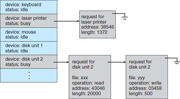
Figure 13.9 Device-status table.
Scheduling I/O operations is one way in which the I/O subsystem improves the efficiency of the computer. Another way is by using storage space in main memory or on disk via buffering, caching, and spooling.
13.4.2 Buffering
A buffer, of course, is a memory area that stores data being transferred between two devices or between a device and an application. Buffering is done for three reasons. One reason is to cope with a speed mismatch between the producer and consumer of a data stream. Suppose, for example, that a file is being received via modem for storage on the hard disk. The modem is about a thousand times slower than the hard disk. So a buffer is created in main memory to accumulate the bytes received from the modem. When an entire buffer of data has arrived, the buffer can be written to disk in a single operation. Since the disk write is not instantaneous and the modem still needs a place to store additional incoming data, two buffers are used. After the modem fills the first buffer, the disk write is requested. The modem then starts to fill the second buffer while the first buffer is written to disk. By the time the modem has filled the second buffer, the disk write from the first one should have completed, so the modem can switch back to the first buffer while the disk writes the second one. This double buffering decouples the producer of data from the consumer, thus relaxing timing requirements between them. The need for this decoupling is illustrated in Figure 13.10, which lists the enormous differences in device speeds for typical computer hardware.
A second use of buffering is to provide adaptations for devices that have different data-transfer sizes. Such disparities are especially common in computer networking, where buffers are used widely for fragmentation and reassembly of messages. At the sending side, a large message is fragmented into small network packets. The packets are sent over the network, and the receiving side places them in a reassembly buffer to form an image of the source data.

Figure 13.10 Sun Enterprise 6000 device-transfer rates (logarithmic).
A third use of buffering is to support copy semantics for application I/O. An example will clarify the meaning of “copy semantics.” Suppose that an application has a buffer of data that it wishes to write to disk. It calls the write() system call, providing a pointer to the buffer and an integer specifying the number of bytes to write. After the system call returns, what happens if the application changes the contents of the buffer? With copy semantics, the version of the data written to disk is guaranteed to be the version at the time of the application system call, independent of any subsequent changes in the application's buffer. A simple way in which the operating system can guarantee copy semantics is for the write() system call to copy the application data into a kernel buffer before returning control to the application. The disk write is performed from the kernel buffer, so that subsequent changes to the application buffer have no effect. Copying of data between kernel buffers and application data space is common in operating systems, despite the overhead that this operation introduces, because of the clean semantics. The same effect can be obtained more efficiently by clever use of virtual memory mapping and copy-on-write page protection.
13.4.3 Caching
A cache is a region of fast memory that holds copies of data. Access to the cached copy is more efficient than access to the original. For instance, the instructions of the currently running process are stored on disk, cached in physical memory, and copied again in the CPU's secondary and primary caches. The difference between a buffer and a cache is that a buffer may hold the only existing copy of a data item, whereas a cache, by definition, holds a copy on faster storage of an item that resides elsewhere.
Caching and buffering are distinct functions, but sometimes a region of memory can be used for both purposes. For instance, to preserve copy semantics and to enable efficient scheduling of disk I/O, the operating system uses buffers in main memory to hold disk data. These buffers are also used as a cache, to improve the I/O efficiency for files that are shared by applications or that are being written and reread rapidly. When the kernel receives a file I/O request, the kernel first accesses the buffer cache to see whether that region of the file is already available in main memory. If it is, a physical disk I/O can be avoided or deferred. Also, disk writes are accumulated in the buffer cache for several seconds, so that large transfers are gathered to allow efficient write schedules. This strategy of delaying writes to improve I/O efficiency is discussed, in the context of remote file access, in Section 17.9.2.
13.4.4 Spooling and Device Reservation
A spool is a buffer that holds output for a device, such as a printer, that cannot accept interleaved data streams. Although a printer can serve only one job at a time, several applications may wish to print their output concurrently, without having their output mixed together. The operating system solves this problem by intercepting all output to the printer. Each application's output is spooled to a separate disk file. When an application finishes printing, the spooling system queues the corresponding spool file for output to the printer. The spooling system copies the queued spool files to the printer one at a time. In some operating systems, spooling is managed by a system daemon process. In others, it is handled by an in-kernel thread. In either case, the operating system provides a control interface that enables users and system administrators to display the queue, remove unwanted jobs before those jobs print, suspend printing while the printer is serviced, and so on.
Some devices, such as tape drives and printers, cannot usefully multiplex the I/O requests of multiple concurrent applications. Spooling is one way operating systems can coordinate concurrent output. Another way to deal with concurrent device access is to provide explicit facilities for coordination. Some operating systems (including VMS) provide support for exclusive device access by enabling a process to allocate an idle device and to deallocate that device when it is no longer needed. Other operating systems enforce a limit of one open file handle to such a device. Many operating systems provide functions that enable processes to coordinate exclusive access among themselves. For instance, Windows provides system calls to wait until a device object becomes available. It also has a parameter to the OpenFile() system call that declares the types of access to be permitted to other concurrent threads. On these systems, it is up to the applications to avoid deadlock.
13.4.5 Error Handling
An operating system that uses protected memory can guard against many kinds of hardware and application errors, so that a complete system failure is not the usual result of each minor mechanical malfunction. Devices and I/O transfers can fail in many ways, either for transient reasons, as when a network becomes overloaded, or for “permanent” reasons, as when a disk controller becomes defective. Operating systems can often compensate effectively for transient failures. For instance, a disk read() failure results in a read() retry, and a network send() error results in a resend(), if the protocol so specifies. Unfortunately, if an important component experiences a permanent failure, the operating system is unlikely to recover.
As a general rule, an I/O system call will return one bit of information about the status of the call, signifying either success or failure. In the UNIX operating system, an additional integer variable named errno is used to return an error code—one of about a hundred values—indicating the general nature of the failure (for example, argument out of range, bad pointer, or file not open). By contrast, some hardware can provide highly detailed error information, although many current operating systems are not designed to convey this information to the application. For instance, a failure of a SCSI device is reported by the SCSI protocol in three levels of detail: a sense key that identifies the general nature of the failure, such as a hardware error or an illegal request; an additional sense code that states the category of failure, such as a bad command parameter or a self-test failure; and an additional sense-code qualifier that gives even more detail, such as which command parameter was in error or which hardware subsystem failed its self-test. Further, many SCSI devices maintain internal pages of error-log information that can be requested by the host—but seldom are.
13.4.6 I/O Protection
Errors are closely related to the issue of protection. A user process may accidentally or purposely attempt to disrupt the normal operation of a system by attempting to issue illegal I/O instructions. We can use various mechanisms to ensure that such disruptions cannot take place in the system.
To prevent users from performing illegal I/O, we define all I/O instructions to be privileged instructions. Thus, users cannot issue I/O instructions directly; they must do it through the operating system. To do I/O, a user program executes a system call to request that the operating system perform I/O on its behalf (Figure 13.11). The operating system, executing in monitor mode, checks that the request is valid and, if it is, does the I/O requested. The operating system then returns to the user.
In addition, any memory-mapped and I/O port memory locations must be protected from user access by the memory-protection system. Note that a kernel cannot simply deny all user access. Most graphics games and video editing and playback software need direct access to memory-mapped graphics controller memory to speed the performance of the graphics, for example. The kernel might in this case provide a locking mechanism to allow a section of graphics memory (representing a window on screen) to be allocated to one process at a time.
13.4.7 Kernel Data Structures
The kernel needs to keep state information about the use of I/O components. It does so through a variety of in-kernel data structures, such as the open-file table structure from Section 12.1. The kernel uses many similar structures to track network connections, character-device communications, and other I/O activities.

Figure 13.11 Use of a system call to perform I/O.
UNIX provides file-system access to a variety of entities, such as user files, raw devices, and the address spaces of processes. Although each of these entities supports a read() operation, the semantics differ. For instance, to read a user file, the kernel needs to probe the buffer cache before deciding whether to perform a disk I/O. To read a raw disk, the kernel needs to ensure that the request size is a multiple of the disk sector size and is aligned on a sector boundary. To read a process image, it is merely necessary to copy data from memory. UNIX encapsulates these differences within a uniform structure by using an object-oriented technique. The open-file record, shown in Figure 13.12, contains a dispatch table that holds pointers to the appropriate routines, depending on the type of file.
Some operating systems use object-oriented methods even more extensively. For instance, Windows uses a message-passing implementation for I/O. An I/O request is converted into a message that is sent through the kernel to the I/O manager and then to the device driver, each of which may change the message contents. For output, the message contains the data to be written. For input, the message contains a buffer to receive the data. The message-passing approach can add overhead, by comparison with procedural techniques that use shared data structures, but it simplifies the structure and design of the I/O system and adds flexibility.

Figure 13.12 UNIX I/O kernel structure.
13.4.8 Kernel I/O Subsystem Summary
In summary, the I/O subsystem coordinates an extensive collection of services that are available to applications and to other parts of the kernel. The I/O subsystem supervises these procedures:
- Management of the name space for files and devices
- Access control to files and devices
- Operation control (for example, a modem cannot seek())
- File-system space allocation
- Device allocation
- Buffering, caching, and spooling
- I/O scheduling
- Device-status monitoring, error handling, and failure recovery
- Device-driver configuration and initialization
The upper levels of the I/O subsystem access devices via the uniform interface provided by the device drivers.
13.5 Transforming I/O Requests to Hardware Operations
Earlier, we described the handshaking between a device driver and a device controller, but we did not explain how the operating system connects an application request to a set of network wires or to a specific disk sector. Consider, for example, reading a file from disk. The application refers to the data by a file name. Within a disk, the file system maps from the file name through the file-system directories to obtain the space allocation of the file. For instance, in MS-DOS, the name maps to a number that indicates an entry in the file-access table, and that table entry tells which disk blocks are allocated to the file. In UNIX, the name maps to an inode number, and the corresponding inode contains the space-allocation information. But how is the connection made from the file name to the disk controller (the hardware port address or the memory-mapped controller registers)?
One method is that used by MS-DOS, a relatively simple operating system. The first part of an MS-DOS file name, preceding the colon, is a string that identifies a specific hardware device. For example, C: is the first part of every file name on the primary hard disk. The fact that C: represents the primary hard disk is built into the operating system; C: is mapped to a specific port address through a device table. Because of the colon separator, the device name space is separate from the file-system name space. This separation makes it easy for the operating system to associate extra functionality with each device. For instance, it is easy to invoke spooling on any files written to the printer.
If, instead, the device name space is incorporated in the regular file-system name space, as it is in UNIX, the normal file-system name services are provided automatically. If the file system provides ownership and access control to all file names, then devices have owners and access control. Since files are stored on devices, such an interface provides access to the I/O system at two levels. Names can be used to access the devices themselves or to access the files stored on the devices.
UNIX represents device names in the regular file-system name space. Unlike an MS-DOS file name, which has a colon separator, a UNIX path name has no clear separation of the device portion. In fact, no part of the path name is the name of a device. UNIX has a mount table that associates prefixes of path names with specific device names. To resolve a path name, UNIX looks up the name in the mount table to find the longest matching prefix; the corresponding entry in the mount table gives the device name. This device name also has the form of a name in the file-system name space. When UNIX looks up this name in the file-system directory structures, it finds not an inode number but a <major, minor> device number. The major device number identifies a device driver that should be called to handle I/O to this device. The minor device number is passed to the device driver to index into a device table. The corresponding device-table entry gives the port address or the memory-mapped address of the device controller.
Modern operating systems gain significant flexibility from the multiple stages of lookup tables in the path between a request and a physical device controller. The mechanisms that pass requests between applications and drivers are general. Thus, we can introduce new devices and drivers into a computer without recompiling the kernel. In fact, some operating systems have the ability to load device drivers on demand. At boot time, the system first probes the hardware buses to determine what devices are present. It then loads in the necessary drivers, either immediately or when first required by an I/O request.

Figure 13.13 The life cycle of an I/O request.
We next describe the typical life cycle of a blocking read request, as depicted in Figure 13.13. The figure suggests that an I/O operation requires a great many steps that together consume a tremendous number of CPU cycles.
- A process issues a blocking read() system call to a file descriptor of a file that has been opened previously.
- The system-call code in the kernel checks the parameters for correctness. In the case of input, if the data are already available in the buffer cache, the data are returned to the process, and the I/O request is completed.
- Otherwise, a physical I/O must be performed. The process is removed from the run queue and is placed on the wait queue for the device, and the I/O request is scheduled. Eventually, the I/O subsystem sends the request to the device driver. Depending on the operating system, the request is sent via a subroutine call or an in-kernel message.
- The device driver allocates kernel buffer space to receive the data and schedules the I/O. Eventually, the driver sends commands to the device controller by writing into the device-control registers.
- The device controller operates the device hardware to perform the data transfer.
- The driver may poll for status and data, or it may have set up a DMA transfer into kernel memory. We assume that the transfer is managed by a DMA controller, which generates an interrupt when the transfer completes.
- The correct interrupt handler receives the interrupt via the interrupt-vector table, stores any necessary data, signals the device driver, and returns from the interrupt.
- The device driver receives the signal, determines which I/O request has completed, determines the request's status, and signals the kernel I/O subsystem that the request has been completed.
- The kernel transfers data or return codes to the address space of the requesting process and moves the process from the wait queue back to the ready queue.
- Moving the process to the ready queue unblocks the process. When the scheduler assigns the process to the CPU, the process resumes execution at the completion of the system call.
13.6 STREAMS
UNIX System V has an interesting mechanism, called STREAMS, that enables an application to assemble pipelines of driver code dynamically. A stream is a full-duplex connection between a device driver and a user-level process. It consists of a stream head that interfaces with the user process, a driver end that controls the device, and zero or more stream modules between the stream head and the driver end. Each of these components contains a pair of queues—a read queue and a write queue. Message passing is used to transfer data between queues. The STREAMS structure is shown in Figure 13.14.
Modules provide the functionality of STREAMS processing; they are pushed onto a stream by use of the ioctl() system call. For example, a process can open a serial-port device via a stream and can push on a module to handle input editing. Because messages are exchanged between queues in adjacent modules, a queue in one module may overflow an adjacent queue. To prevent this from occurring, a queue may support flow control. Without flow control, a queue accepts all messages and immediately sends them on to the queue in the adjacent module without buffering them. A queue that supports flow control buffers messages and does not accept messages without sufficient buffer space. This process involves exchanges of control messages between queues in adjacent modules.

Figure 13.14 The STREAMS structure.
A user process writes data to a device using either the write() or putmsg() system call. The write() system call writes raw data to the stream, whereas putmsg() allows the user process to specify a message. Regardless of the system call used by the user process, the stream head copies the data into a message and delivers it to the queue for the next module in line. This copying of messages continues until the message is copied to the driver end and hence the device. Similarly, the user process reads data from the stream head using either the read() or getmsg() system call. If read() is used, the stream head gets a message from its adjacent queue and returns ordinary data (an unstructured byte stream) to the process. If getmsg() is used, a message is returned to the process.
STREAMS I/O is asynchronous (or nonblocking) except when the user process communicates with the stream head. When writing to the stream, the user process will block, assuming the next queue uses flow control, until there is room to copy the message. Likewise, the user process will block when reading from the stream until data are available.
As mentioned, the driver end—like the stream head and modules—has a read and write queue. However, the driver end must respond to interrupts, such as one triggered when a frame is ready to be read from a network. Unlike the stream head, which may block if it is unable to copy a message to the next queue in line, the driver end must handle all incoming data. Drivers must support flow control as well. However, if a device's buffer is full, the device typically resorts to dropping incoming messages. Consider a network card whose input buffer is full. The network card must simply drop further messages until there is enough buffer space to store incoming messages.
The benefit of using STREAMS is that it provides a framework for a modular and incremental approach to writing device drivers and network protocols. Modules may be used by different streams and hence by different devices. For example, a networking module may be used by both an Ethernet network card and a 802.11 wireless network card. Furthermore, rather than treating character-device I/O as an unstructured byte stream, STREAMS allows support for message boundaries and control information when communicating between modules. Most UNIX variants support STREAMS, and it is the preferred method for writing protocols and device drivers. For example, System V UNIX and Solaris implement the socket mechanism using STREAMS.
13.7 Performance
I/O is a major factor in system performance. It places heavy demands on the CPU to execute device-driver code and to schedule processes fairly and efficiently as they block and unblock. The resulting context switches stress the CPU and its hardware caches. I/O also exposes any inefficiencies in the interrupt-handling mechanisms in the kernel. In addition, I/O loads down the memory bus during data copies between controllers and physical memory and again during copies between kernel buffers and application data space. Coping gracefully with all these demands is one of the major concerns of a computer architect.
Although modern computers can handle many thousands of interrupts per second, interrupt handling is a relatively expensive task. Each interrupt causes the system to perform a state change, to execute the interrupt handler, and then to restore state. Programmed I/O can be more efficient than interrupt-driven I/O, if the number of cycles spent in busy waiting is not excessive. An I/O completion typically unblocks a process, leading to the full overhead of a context switch.
Network traffic can also cause a high context-switch rate. Consider, for instance, a remote login from one machine to another. Each character typed on the local machine must be transported to the remote machine. On the local machine, the character is typed; a keyboard interrupt is generated; and the character is passed through the interrupt handler to the device driver, to the kernel, and then to the user process. The user process issues a network I/O system call to send the character to the remote machine. The character then flows into the local kernel, through the network layers that construct a network packet, and into the network device driver. The network device driver transfers the packet to the network controller, which sends the character and generates an interrupt. The interrupt is passed back up through the kernel to cause the network I/O system call to complete.
Now, the remote system's network hardware receives the packet, and an interrupt is generated. The character is unpacked from the network protocols and is given to the appropriate network daemon. The network daemon identifies which remote login session is involved and passes the packet to the appropriate subdaemon for that session. Throughout this flow, there are context switches and state switches (Figure 13.15). Usually, the receiver echoes the character back to the sender; that approach doubles the work.

Figure 13.15 Intercomputer communications.
To eliminate the context switches involved in moving each character between daemons and the kernel, the Solaris developers reimplemented the telnet daemon using in-kernel threads. Sun estimated that this improvement increased the maximum number of network logins from a few hundred to a few thousand on a large server.
Other systems use separate front-end processors for terminal I/O to reduce the interrupt burden on the main CPU. For instance, a terminal concentrator can multiplex the traffic from hundreds of remote terminals into one port on a large computer. An I/O channel is a dedicated, special-purpose CPU found in mainframes and in other high-end systems. The job of a channel is to offload I/O work from the main CPU. The idea is that the channels keep the data flowing smoothly, while the main CPU remains free to process the data. Like the device controllers and DMA controllers found in smaller computers, a channel can process more general and sophisticated programs, so channels can be tuned for particular workloads.
We can employ several principles to improve the efficiency of I/O:
- Reduce the number of context switches.
- Reduce the number of times that data must be copied in memory while passing between device and application.
- Reduce the frequency of interrupts by using large transfers, smart controllers, and polling (if busy waiting can be minimized).
- Increase concurrency by using DMA-knowledgeable controllers or channels to offload simple data copying from the CPU.
- Move processing primitives into hardware, to allow their operation in device controllers to be concurrent with CPU and bus operation.
- Balance CPU, memory subsystem, bus, and I/O performance, because an overload in any one area will cause idleness in others.
I/O devices vary greatly in complexity. For instance, a mouse is simple. The mouse movements and button clicks are converted into numeric values that are passed from hardware, through the mouse device driver, to the application. By contrast, the functionality provided by the Windows disk device driver is complex. It not only manages individual disks but also implements RAID arrays (Section 10.7). To do so, it converts an application's read or write request into a coordinated set of disk I/O operations. Moreover, it implements sophisticated error-handling and data-recovery algorithms and takes many steps to optimize disk performance.
Where should the I/O functionality be implemented—in the device hardware, in the device driver, or in application software? Sometimes we observe the progression depicted in Figure 13.16.
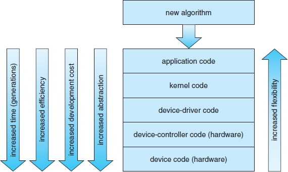
Figure 13.16 Device functionality progression.
- Initially, we implement experimental I/O algorithms at the application level, because application code is flexible and application bugs are unlikely to cause system crashes. Furthermore, by developing code at the application level, we avoid the need to reboot or reload device drivers after every change to the code. An application-level implementation can be inefficient, however, because of the overhead of context switches and because the application cannot take advantage of internal kernel data structures and kernel functionality (such as efficient in-kernel messaging, threading, and locking).
- When an application-level algorithm has demonstrated its worth, we may reimplement it in the kernel. This can improve performance, but the development effort is more challenging, because an operating-system kernel is a large, complex software system. Moreover, an in-kernel implementation must be thoroughly debugged to avoid data corruption and system crashes.
- The highest performance may be obtained through a specialized implementation in hardware, either in the device or in the controller. The disadvantages of a hardware implementation include the difficulty and expense of making further improvements or of fixing bugs, the increased development time (months rather than days), and the decreased flexibility. For instance, a hardware RAID controller may not provide any means for the kernel to influence the order or location of individual block reads and writes, even if the kernel has special information about the workload that would enable it to improve the I/O performance.
13.8 Summary
The basic hardware elements involved in I/O are buses, device controllers, and the devices themselves. The work of moving data between devices and main memory is performed by the CPU as programmed I/O or is offloaded to a DMA controller. The kernel module that controls a device is a device driver. The system-call interface provided to applications is designed to handle several basic categories of hardware, including block devices, character devices, memory-mapped files, network sockets, and programmed interval timers. The system calls usually block the processes that issue them, but nonblocking and asynchronous calls are used by the kernel itself and by applications that must not sleep while waiting for an I/O operation to complete.
The kernel's I/O subsystem provides numerous services. Among these are I/O scheduling, buffering, caching, spooling, device reservation, and error handling. Another service, name translation, makes the connections between hardware devices and the symbolic file names used by applications. It involves several levels of mapping that translate from character-string names, to specific device drivers and device addresses, and then to physical addresses of I/O ports or bus controllers. This mapping may occur within the file-system name space, as it does in UNIX, or in a separate device name space, as it does in MS-DOS.
STREAMS is an implementation and methodology that provides a framework for a modular and incremental approach to writing device drivers and network protocols. Through streams, drivers can be stacked, with data passing through them sequentially and bidirectionally for processing.
I/O system calls are costly in terms of CPU consumption because of the many layers of software between a physical device and an application. These layers imply overhead from several sources: context switching to cross the kernel's protection boundary, signal and interrupt handling to service the I/O devices, and the load on the CPU and memory system to copy data between kernel buffers and application space.
Practice Exercises
13.1 State three advantages of placing functionality in a device controller, rather than in the kernel. State three disadvantages.
13.2 The example of handshaking in Section 13.2 used two bits: a busy bit and a command-ready bit. Is it possible to implement this handshaking with only one bit? If it is, describe the protocol. If it is not, explain why one bit is insufficient.
13.3 Why might a system use interrupt-driven I/O to manage a single serial port and polling I/O to manage a front-end processor, such as a terminal concentrator?
13.4 Polling for an I/O completion can waste a large number of CPU cycles if the processor iterates a busy-waiting loop many times before the I/O completes. But if the I/O device is ready for service, polling can be much more efficient than is catching and dispatching an interrupt. Describe a hybrid strategy that combines polling, sleeping, and interrupts for I/O device service. For each of these three strategies (pure polling, pure interrupts, hybrid), describe a computing environment in which that strategy is more efficient than is either of the others.
13.5 How does DMA increase system concurrency? How does it complicate hardware design?
13.6 Why is it important to scale up system-bus and device speeds as CPU speed increases?
13.7 Distinguish between a STREAMS driver and a STREAMS module.
Exercises
13.8 When multiple interrupts from different devices appear at about the same time, a priority scheme could be used to determine the order in which the interrupts would be serviced. Discuss what issues need to be considered in assigning priorities to different interrupts.
13.9 What are the advantages and disadvantages of supporting memory-mapped I/O to device control registers?
13.10 Consider the following I/O scenarios on a single-user PC:
- A mouse used with a graphical user interface
- A tape drive on a multitasking operating system (with no device preallocation available)
- A disk drive containing user files
- A graphics card with direct bus connection, accessible through memory-mapped I/O
For each of these scenarios, would you design the operating system to use buffering, spooling, caching, or a combination? Would you use polled I/O or interrupt-driven I/O? Give reasons for your choices.
13.11 In most multiprogrammed systems, user programs access memory through virtual addresses, while the operating system uses raw physical addresses to access memory. What are the implications of this design for the initiation of I/O operations by the user program and their execution by the operating system?
13.12 What are the various kinds of performance overhead associated with servicing an interrupt?
13.13 Describe three circumstances under which blocking I/O should be used. Describe three circumstances under which nonblocking I/O should be used. Why not just implement nonblocking I/O and have processes busy-wait until their devices are ready?
13.14 Typically, at the completion of a device I/O, a single interrupt is raised and appropriately handled by the host processor. In certain settings, however, the code that is to be executed at the completion of the I/O can be broken into two separate pieces. The first piece executes immediately after the I/O completes and schedules a second interrupt for the remaining piece of code to be executed at a later time. What is the purpose of using this strategy in the design of interrupt handlers?
13.15 Some DMA controllers support direct virtual memory access, where the targets of I/O operations are specified as virtual addresses and a translation from virtual to physical address is performed during the DMA. How does this design complicate the design of the DMA controller? What are the advantages of providing such functionality?
13.16 UNIX coordinates the activities of the kernel I/O components by manipulating shared in-kernel data structures, whereas Windows uses object-oriented message passing between kernel I/O components. Discuss three pros and three cons of each approach.
13.17 Write (in pseudocode) an implementation of virtual clocks, including the queueing and management of timer requests for the kernel and applications. Assume that the hardware provides three timer channels.
13.18 Discuss the advantages and disadvantages of guaranteeing reliable transfer of data between modules in the STREAMS abstraction.
Bibliographical Notes
[Vahalia (1996)] provides a good overview of I/O and networking in UNIX. [McKusick and Neville-Neil (2005)] detail the I/O structures and methods employed in FreeBSD. The use and programming of the various interprocess-communication and network protocols in UNIX are explored in [Stevens (1992)]. [Hart (2005)] covers Windows programming.
[Intel (2011)] provides a good source for Intel processors. [Rago (1993)] provides a good discussion of STREAMS. [Hennessy and Patterson (2012)] describe multiprocessor systems and cache-consistency issues.
Bibliography
[Hart (2005)] J. M. Hart, Windows System Programming, Third Edition, Addison-Wesley (2005).
[Hennessy and Patterson (2012)] J. Hennessy and D. Patterson, Computer Architecture: A Quantitative Approach, Fifth Edition, Morgan Kaufmann (2012).
[Intel (2011)] Intel 64 and IA-32 Architectures Software Developer's Manual, Combined Volumes: 1, 2A, 2B, 3A and 3B. Intel Corporation (2011).
[McKusick and Neville-Neil (2005)] M. K. McKusick and G. V. Neville-Neil, The Design and Implementation of the FreeBSD UNIX Operating System, Addison Wesley (2005).
[Rago (1993)] S. Rago, UNIX System V Network Programming, Addison-Wesley (1993).
[Stevens (1992)] R. Stevens, Advanced Programming in the UNIX Environment, Addison-Wesley (1992).
[Vahalia (1996)] U. Vahalia, Unix Internals: The New Frontiers, Prentice Hall (1996).