
CHAPTER 17
Distributed Systems
A distributed system is a collection of processors that do not share memory or a clock. Instead, each node has its own local memory. The nodes communicate with one another through various networks, such as high-speed buses and the Internet. In this chapter, we discuss the general structure of distributed systems and the networks that interconnect them. We also contrast the main differences in operating-system design between these systems and centralized systems.
CHAPTER OBJECTIVES
- To provide a high-level overview of distributed systems and the networks that interconnect them.
- To describe the general structure of distributed operating systems.
- To explain general communication structure and communication protocols.
- To discuss issues concerning the design of distributed systems.
17.1 Advantages of Distributed Systems
A distributed system is a collection of loosely coupled nodes interconnected by a communication network. From the point of view of a specific node in a distributed system, the rest of the nodes and their respective resources are remote, whereas its own resources are local.
The nodes in a distributed system may vary in size and function. They may include small microprocessors, personal computers, and large general-purpose computer systems. These processors are referred to by a number of names, such as processors, sites, machines, and hosts, depending on the context in which they are mentioned. We mainly use site to indicate the location of a machine and node to refer to a specific system at a site. Generally, one node at one site, the server, has a resource that another node at another site, the client (or user), would like to use. A general structure of a distributed system is shown in Figure 17.1.
There are four major reasons for building distributed systems: resource sharing, computation speedup, reliability, and communication. In this section, we briefly discuss each of them.

Figure 17.1 A distributed system.
17.1.1 Resource Sharing
If a number of different sites (with different capabilities) are connected to one another, then a user at one site may be able to use the resources available at another. For example, a user at site A may be using a laser printer located at site B. Meanwhile, a user at B may access a file that resides at A. In general, resource sharing in a distributed system provides mechanisms for sharing files at remote sites, processing information in a distributed database, printing files at remote sites, using remote specialized hardware devices (such as a supercomputer), and performing other operations.
17.1.2 Computation Speedup
If a particular computation can be partitioned into subcomputations that can run concurrently, then a distributed system allows us to distribute the subcomputations among the various sites. The subcomputations can be run concurrently and thus provide computation speedup. In addition, if a particular site is currently overloaded with jobs, some of them can be moved to other, lightly loaded sites. This movement of jobs is called load sharing or job migration. Automated load sharing, in which the distributed operating system automatically moves jobs, is not yet common in commercial systems.
17.1.3 Reliability
If one site fails in a distributed system, the remaining sites can continue operating, giving the system better reliability. If the system is composed of multiple large autonomous installations (that is, general-purpose computers), the failure of one of them should not affect the rest. If, however, the system is composed of small machines, each of which is responsible for some crucial system function (such as the web server or the file system), then a single failure may halt the operation of the whole system. In general, with enough redundancy (in both hardware and data), the system can continue operation, even if some of its sites have failed.
The failure of a site must be detected by the system, and appropriate action may be needed to recover from the failure. The system must no longer use the services of that site. In addition, if the function of the failed site can be taken over by another site, the system must ensure that the transfer of function occurs correctly. Finally, when the failed site recovers or is repaired, mechanisms must be available to integrate it back into the system smoothly.
17.1.4 Communication
When several sites are connected to one another by a communication network, users at the various sites have the opportunity to exchange information. At a low level, messages are passed between systems, much as messages are passed between processes in the single-computer message system discussed in Section 3.4. Given message passing, all the higher-level functionality found in standalone systems can be expanded to encompass the distributed system. Such functions include file transfer, login, mail, and remote procedure calls (RPCs).
The advantage of a distributed system is that these functions can be carried out over great distances. Two people at geographically distant sites can collaborate on a project, for example. By transferring the files of the project, logging in to each other's remote systems to run programs, and exchanging mail to coordinate the work, users minimize the limitations inherent in long-distance work. We wrote this book by collaborating in such a manner.
The advantages of distributed systems have resulted in an industry-wide trend toward downsizing. Many companies are replacing their mainframes with networks of workstations or personal computers. Companies get a bigger bang for the buck (that is, better functionality for the cost), more flexibility in locating resources and expanding facilities, better user interfaces, and easier maintenance.
17.2 Types of Network-based Operating Systems
In this section, we describe the two general categories of network-oriented operating systems: network operating systems and distributed operating systems. Network operating systems are simpler to implement but generally more difficult for users to access and utilize than are distributed operating systems, which provide more features.
17.2.1 Network Operating Systems
A network operating system provides an environment in which users, who are aware of the multiplicity of machines, can access remote resources by either logging in to the appropriate remote machine or transferring data from the remote machine to their own machines. Currently, all general-purpose operating systems, and even embedded operating systems such as Android and iOS, are network operating systems.
17.2.1.1 Remote Login
An important function of a network operating system is to allow users to log in remotely. The Internet provides the ssh facility for this purpose. To illustrate, let's suppose that a user at Westminster College wishes to compute on cs.yale.edu, a computer that is located at Yale University. To do so, the user must have a valid account on that machine. To log in remotely, the user issues the command
ssh cs.yale.edu
This command results in the formation of an encrypted socket connection between the local machine at Westminster College and the “cs.yale.edu” computer. After this connection has been established, the networking software creates a transparent, bidirectional link so that all characters entered by the user are sent to a process on “cs.yale.edu” and all the output from that process is sent back to the user. The process on the remote machine asks the user for a login name and a password. Once the correct information has been received, the process acts as a proxy for the user, who can compute on the remote machine just as any local user can.
17.2.1.2 Remote File Transfer
Another major function of a network operating system is to provide a mechanism for remote file transfer from one machine to another. In such an environment, each computer maintains its own local file system. If a user at one site (say, cs.uvm.edu) wants to access a file located on another computer (say, cs.yale.edu), then the file must be copied explicitly from the computer at Yale to the computer at the University of Vermont.
The Internet provides a mechanism for such a transfer with the file transfer protocol (FTP) program and the more private secure file transfer protocol (SFTP) program. Suppose that a user on “cs.uvm.edu” wants to copy a Java program Server.java that resides on “cs.yale.edu.” The user must first invoke the sftp program by executing
sftp cs.yale.edu
The program then asks the user for a login name and a password. Once the correct information has been received, the user must connect to the subdirectory where the file Server.java resides and then copy the file by executing
get Server.java
In this scheme, the file location is not transparent to the user; users must know exactly where each file is. Moreover, there is no real file sharing, because a user can only copy a file from one site to another. Thus, several copies of the same file may exist, resulting in a waste of space. In addition, if these copies are modified, the various copies will be inconsistent.
Notice that, in our example, the user at the University of Vermont must have login permission on “cs.yale.edu.” FTP also provides away to allow a user who does not have an account on the Yale computer to copy files remotely. This remote copying is accomplished through the “anonymous FTP” method, which works as follows. The file to be copied (that is, Server.java) must be placed in a special subdirectory (say, ftp) with the protection set to allow the public to read the file. A user who wishes to copy the file uses the ftp command. When the user is asked for the login name, the user supplies the name “anonymous” and an arbitrary password.
Once anonymous login is accomplished, the system must ensure that this partially authorized user does not access inappropriate files. Generally, the user is allowed to access only those files that are in the directory tree of user “anonymous.” Any files placed here are accessible to any anonymous users, subject to the usual file-protection scheme used on that machine. Anonymous users, however, cannot access files outside of this directory tree.
Implementation of the FTP mechanism is similar to ssh implementation. A daemon on the remote site watches for requests to connect to the system's FTP port. Login authentication is accomplished, and the user is allowed to execute transfer commands remotely. Unlike the ssh daemon, which executes any command for the user, the FTP daemon responds only to a predefined set of file-related commands. These include the following:
- get—Transfer a file from the remote machine to the local machine.
- put—Transfer from the local machine to the remote machine.
- ls or dir—List files in the current directory on the remote machine.
- cd—Change the current directory on the remote machine.
There are also various commands to change transfer modes (for binary or ASCII files) and to determine connection status.
An important point about ssh and FTP is that they require the user to change paradigms. FTP requires the user to know a command set entirely different from the normal operating-system commands. With ssh, the user must know appropriate commands on the remote system. For instance, a user on a Windows machine who connects remotely to a UNIX machine must switch to UNIX commands for the duration of the ssh session. (In networking, a session is a complete round of communication, frequently beginning with a login to authenticate and ending with a logoff to terminate the communication.) Obviously, users would find it more convenient not to be required to use a different set of commands. Distributed operating systems are designed to address this problem.
17.2.2 Distributed Operating Systems
In a distributed operating system, users access remote resources in the same way they access local resources. Data and process migration from one site to another is under the control of the distributed operating system.
17.2.2.1 Data Migration
Suppose a user on site A wants to access data (such as a file) that reside at site B. The system can transfer the data by one of two basic methods. One approach to data migration is to transfer the entire file to site A. From that point on, all access to the file is local. When the user no longer needs access to the file, a copy of the file (if it has been modified) is sent back to site B. Even if only a modest change has been made to a large file, all the data must be transferred. This mechanism can be thought of as an automated FTP system. This approach was used in the Andrew file system, but it was found to be too inefficient.
The other approach is to transfer to site A only those portions of the file that are actually necessary for the immediate task. If another portion is required later, another transfer will take place. When the user no longer wants to access the file, any part of it that has been modified must be sent back to site B. (Note the similarity to demand paging.) The Sun Microsystems network file system (NFS) protocol uses this method (Section 12.8), as do newer versions of Andrew. The Microsoft SMB protocol (also known as Common Internet File System, or CIFS) also allows file sharing over a network. SMB is described in Section 19.6.2.1.
Clearly, if only a small part of a large file is being accessed, the latter approach is preferable. If significant portions of the file are being accessed, however, it is more efficient to copy the entire file. Whichever method is used, data migration includes more than the mere transfer of data from one site to another. The system must also perform various data translations if the two sites involved are not directly compatible (for instance, if they use different character-code representations or represent integers with a different number or order of bits).
17.2.2.2 Computation Migration
In some circumstances, we may want to transfer the computation, rather than the data, across the system; this process is called computation migration. For example, consider a job that needs to access various large files that reside at different sites, to obtain a summary of those files. It would be more efficient to access the files at the sites where they reside and return the desired results to the site that initiated the computation. Generally, if the time to transfer the data is longer than the time to execute the remote command, the remote command should be used.
Such a computation can be carried out in different ways. Suppose that process P wants to access a file at site A. Access to the file is carried out at site A and could be initiated by an RPC. An RPC uses network protocols to execute a routine on a remote system (Section 3.6.2). Process P invokes a predefined procedure at site A. The procedure executes appropriately and then returns the results to P.
Alternatively, process P can send a message to site A. The operating system at site A then creates a new process Q whose function is to carry out the designated task. When process Q completes its execution, it sends the needed result back to P via the message system. In this scheme, process P may execute concurrently with process Q. In fact, it may have several processes running concurrently on several sites.
Either method could be used to access several files residing at various sites. One RPC might result in the invocation of another RPC or even in the transfer of messages to another site. Similarly, process Q could, during the course of its execution, send a message to another site, which in turn would create another process. This process might either send a message back to Q or repeat the cycle.
17.2.2.3 Process Migration
A logical extension of computation migration is process migration. When a process is submitted for execution, it is not always executed at the site at which it is initiated. The entire process, or parts of it, may be executed at different sites. This scheme may be used for several reasons:
- Load balancing. The processes (or subprocesses) may be distributed across the network to even the workload.
- Computation speedup. If a single process can be divided into a number of subprocesses that can run concurrently on different sites, then the total process turnaround time can be reduced.
- Hardware preference. The process may have characteristics that make it more suitable for execution on some specialized processor (such as matrix inversion on an array processor) rather than on a microprocessor.
- Software preference. The process may require software that is available at only a particular site, and either the software cannot be moved, or it is less expensive to move the process.
- Data access. Just as in computation migration, if the data being used in the computation are numerous, it may be more efficient to have a process run remotely than to transfer all the data.
We use two complementary techniques to move processes in a computer network. In the first, the system can attempt to hide the fact that the process has migrated from the client. The client then need not code her program explicitly to accomplish the migration. This method is usually employed for achieving load balancing and computation speedup among homogeneous systems, as they do not need user input to help them execute programs remotely.
The other approach is to allow (or require) the user to specify explicitly how the process should migrate. This method is usually employed when the process must be moved to satisfy a hardware or software preference.
You have probably realized that the World Wide Web has many aspects of a distributed computing environment. Certainly it provides data migration (between a web server and a web client). It also provides computation migration. For instance, a web client could trigger a database operation on a web server. Finally, with Java, Javascript, and similar languages, it provides a form of process migration: Java applets and Javascript scripts are sent from the server to the client, where they are executed. A network operating system provides most of these features, but a distributed operating system makes them seamless and easily accessible. The result is a powerful and easy-to-use facility—one of the reasons for the huge growth of the World Wide Web.
17.3 Network Structure
There are basically two types of networks: local-area networks (LAN) and wide-area networks (WAN). The main difference between the two is the way in which they are geographically distributed. Local-area networks are composed of hosts distributed over small areas (such as a single building or a number of adjacent buildings), whereas wide-area networks are composed of systems distributed over a large area (such as the United States). These differences imply major variations in the speed and reliability of the communications networks, and they are reflected in the distributed operating-system design.
17.3.1 Local-Area Networks
Local-area networks emerged in the early 1970s as a substitute for large mainframe computer systems. For many enterprises, it is more economical to have a number of small computers, each with its own self-contained applications, than to have a single large system. Because each small computer is likely to need a full complement of peripheral devices (such as disks and printers), and because some form of data sharing is likely to occur in a single enterprise, it was a natural step to connect these small systems into a network.
LANs, as mentioned, are usually designed to cover a small geographical area, and they are generally used in an office environment. All the sites in such systems are close to one another, so the communication links tend to have a higher speed and lower error rate than do their counterparts in wide-area networks.
The most common links in a local-area network are twisted-pair and fiber-optic cabling. The most common configuration is the star network. In a star network, the nodes connect to one or more switches, and the switches connect to each other, enabling any two nodes to communicate. Communication speeds range from 1 megabit per second for networks such as AppleTalk, infrared, and the Bluetooth local radio network to 40 gigabits per second for the fastest Ethernet. Ten megabits per second is the speed of 10BaseT Ethernet. 100BaseT Ethernet and 1000BaseT Ethernet provide throughputs of 100 megabits and 1 gigabit per second over twisted-pair copper cable. The use of optical-fiber cabling is growing; it provides higher communication rates over longer distances than are possible with copper.
A typical LAN may consist of a number of different computers (from mainframes to laptops or other mobile devices), various shared peripheral devices (such as laser printers and storage arrays), and one or more routers (specialized network communication processors) that provide access to other networks (Figure 17.2). Ethernet is commonly used to construct LANs. An Ethernet network has no central controller, because it is a multiaccess bus, so new hosts can be added easily to the network. The Ethernet protocol is defined by the IEEE 802.3 standard.
The wireless spectrum is increasingly used for designing local-area networks. Wireless (or WiFi) technology allows us to construct a network using only a wireless router to transmit signals between hosts. Each host has a wireless transmitter and receiver that it uses to participate in the network. A disadvantage of wireless networks concerns their speed. Whereas Ethernet systems often run at 1 gigabit per second, WiFi networks typically run considerably slower. There are several IEEE standards for wireless networks. The 802.11g standard can theoretically run at 54 megabits per second, but in practice, data rates are often less than half that. The recent 802.11n standard provides theoretically much higher data rates. In actual practice, though, these networks have typical data rates of around 75 megabits per second. Data rates of wireless networks are heavily influenced by the distance between the wireless router and the host, as well as interference in the wireless spectrum. On the positive side, wireless networks often have a physical advantage over wired Ethernet networks because they require no cabling to connect communicating hosts. As a result, wireless networks are popular in homes and businesses, as well as public areas such as libraries, Internet cafes, sports arenas, and even buses and airplanes.

Figure 17.2 Local-area network.
17.3.2 Wide-Area Networks
Wide-area networks emerged in the late 1960s, mainly as an academic research project to provide efficient communication among sites, allowing hardware and software to be shared conveniently and economically by a wide community of users. The first WAN to be designed and developed was the Arpanet. Begun in 1968, the Arpanet has grown from a four-site experimental network to a worldwide network of networks, the Internet, comprising millions of computer systems.
Because the sites in a WAN are physically distributed over a large geographical area, the communication links are, by default, relatively slow and unreliable. Typical links are telephone lines, leased (dedicated data) lines, optical cable, microwave links, radio waves, and satellite channels. These communication links are controlled by special communication processors (Figure 17.3), commonly known as gateway routers or simply routers, that are responsible for defining the interface through which the sites communicate over the network, as well as for transferring information among the various sites.
For example, the Internet WAN enables hosts at geographically separated sites to communicate with one another. The host computers typically differ from one another in speed, CPU type, operating system, and so on. Hosts are generally on LANs, which are, in turn, connected to the Internet via regional networks. The regional networks, such as NSFnet in the northeast United States, are interlinked with routers (Section 17.4.2) to form the worldwide network. Connections between networks sometimes use a telephone-system service called T1, which provides a transfer rate of 1.544 megabits per second over a leased line. For sites requiring faster Internet access, T1s are collected into multiple-T1 units that work in parallel to provide more throughput. For instance, a T3 is composed of 28 T1 connections and has a transfer rate of 45 megabits per second. Connections such as OC-12 are common and provide 622 megabits per second. Residences can connect to the Internet by either telephone, cable, or specialized Internet service providers that install routers to connect the residences to central services. Of course, there are other WANs besides the Internet. A company might create its own private WAN for increased security, performance, or reliability.

Figure 17.3 Communication processors in a wide-area network.
As mentioned, WANs are generally slower than LANs, although backbone WAN connections that link major cities may have transfer rates of over 40 gigabits per second. Frequently, WANs and LANs interconnect, and it is difficult to tell where one ends and the other starts. Consider the cellular phone data network. Cell phones are used for both voice and data communications. Cell phones in a given area connect via radio waves to a cell tower that contains receivers and transmitters. This part of the network is similar to a LAN except that the cell phones do not communicate with each other (unless two people talking or exchanging data happen to be connected to the same tower). Rather, the towers are connected to other towers and to hubs that connect the tower communications to land lines or other communication mediums and route the packets toward their destinations. This part of the network is more WAN-like. Once the appropriate tower receives the packets, it uses its transmitters to send them to the correct recipient.
17.4 Communication Structure
Now that we have discussed the physical aspects of networking, we turn to the internal workings. The designer of a communication network must address five basic issues:
- Naming and name resolution. How do two processes locate each other to communicate?
- Routing strategies. How are messages sent through the network?
- Packet strategies. Are packets sent individually or as a sequence?
- Connection strategies. How do two processes send a sequence of messages?
In the following sections, we elaborate on each of these issues.
17.4.1 Naming and Name Resolution
The first issue in network communication involves the naming of the systems in the network. For a process at site A to exchange information with a process at site B, each must be able to specify the other. Within a computer system, each process has a process identifier, and messages may be addressed with the process identifier. Because networked systems share no memory, however, a host within the system initially has no knowledge about the processes on other hosts.
To solve this problem, processes on remote systems are generally identified by the pair <host name, identifier>, where host name is a name unique within the network and identifier is a process identifier or other unique number within that host. A host name is usually an alphanumeric identifier, rather than a number, to make it easier for users to specify. For instance, site A might have hosts named homer, marge, bart, and lisa. Bart is certainly easier to remember than is 12814831100.
Names are convenient for humans to use, but computers prefer numbers for speed and simplicity. For this reason, there must be a mechanism to resolve the host name into a host-id that describes the destination system to the networking hardware. This mechanism is similar to the name-to-address binding that occurs during program compilation, linking, loading, and execution (Chapter 8). In the case of host names, two possibilities exist. First, every host may have a data file containing the names and addresses of all the other hosts reachable on the network (similar to binding at compile time). The problem with this model is that adding or removing a host from the network requires updating the data files on all the hosts. The alternative is to distribute the information among systems on the network. The network must then use a protocol to distribute and retrieve the information. This scheme is like execution-time binding. The first method was the one originally used on the Internet. As the Internet grew, however, it became untenable. The second method, the domain-name system (DNS), is the one now in use.
DNS specifies the naming structure of the hosts, as well as name-to-address resolution. Hosts on the Internet are logically addressed with multipart names known as IP addresses. The parts of an IP address progress from the most specific to the most general, with periods separating the fields. For instance, bob.cs.brown.edu refers to host bob in the Department of Computer Science at Brown University within the top-level domain edu. (Other top-level domains include com for commercial sites and org for organizations, as well as a domain for each country connected to the network, for systems specified by country rather than organization type.) Generally, the system resolves addresses by examining the host-name components in reverse order. Each component has a name server—simply a process on a system—that accepts a name and returns the address of the name server responsible for that name. As the final step, the name server for the host in question is contacted, and a host-id is returned. For example, a request made by a process on system A to communicate with bob.cs.brown.edu would result in the following steps:
- The system library or the kernel on system A issues a request to the name server for the edu domain, asking for the address of the name server for brown.edu. The name server for the edu domain must be at a known address, so that it can be queried.
- The edu name server returns the address of the host on which the brown.edu name server resides.
- System A then queries the name server at this address and asks about cs.brown.edu.
- An address is returned. Now, finally, a request to that address for bob.cs.brown.edu returns an Internet address host-id for that host (for example, 128.148.31.100).
This protocol may seem inefficient, but individual hosts cache the IP addresses they have already resolved to speed the process. (Of course, the contents of these caches must be refreshed over time in case the name server is moved or its address changes.) In fact, the protocol is so important that it has been optimized many times and has had many safeguards added. Consider what would happen if the primary edu name server crashed. It is possible that no edu hosts would be able to have their addresses resolved, making them all unreachable! The solution is to use secondary, backup name servers that duplicate the contents of the primary servers.
Before the domain-name service was introduced, all hosts on the Internet needed to have copies of a file that contained the names and addresses of each host on the network. All changes to this file had to be registered at one site (host SRI-NIC), and periodically all hosts had to copy the updated file from SRI-NIC to be able to contact new systems or find hosts whose addresses had changed. Under the domain-name service, each name-server site is responsible for updating the host information for that domain. For instance, any host changes at Brown University are the responsibility of the name server for brown.edu and need not be reported anywhere else. DNS lookups will automatically retrieve the updated information because they will contact brown.edu directly. Domains may contain autonomous subdomains to further distribute the responsibility for host-name and host-id changes.
Java provides the necessary API to design a program that maps IP names to IP addresses. The program shown in Figure 17.4 is passed an IP name (such as bob.cs.brown.edu) on the command line and either outputs the IP address of the host or returns a message indicating that the host name could not be resolved. An InetAddress is a Java class representing an IP name or address. The static method getByName() belonging to the InetAddress class is passed a string representation of an IP name, and it returns the corresponding InetAddress. The program then invokes the getHostAddress() method, which internally uses DNS to look up the IP address of the designated host.
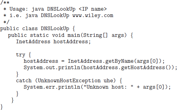
Figure 17.4 Java program illustrating a DNS lookup.
Generally, the operating system is responsible for accepting from its processes a message destined for <host name, identifier> and for transferring that message to the appropriate host. The kernel on the destination host is then responsible for transferring the message to the process named by the identifier. This exchange is by no means trivial; it is described in Section 17.4.4.
17.4.2 Routing Strategies
When a process at site A wants to communicate with a process at site B, how is the message sent? If there is only one physical path from A to B, the message must be sent through that path. However, if there are multiple physical paths from A to B, then several routing options exist. Each site has a routing table indicating the alternative paths that can be used to send a message to other sites. The table may include information about the speed and cost of the various communication paths, and it may be updated as necessary, either manually or via programs that exchange routing information. The three most common routing schemes are fixed routing, virtual routing, and dynamic routing.
- Fixed routing. A path from A to B is specified in advance and does not change unless a hardware failure disables it. Usually, the shortest path is chosen, so that communication costs are minimized.
- Virtual routing. A path from A to B is fixed for the duration of one session. Different sessions involving messages from A to B may use different paths. A session could be as short as a file transfer or as long as a remote-login period.
- Dynamic routing. The path used to send a message from site A to site B is chosen only when the message is sent. Because the decision is made dynamically, separate messages may be assigned different paths. Site A will make a decision to send the message to site C. C, in turn, will decide to send it to site D, and so on. Eventually, a site will deliver the message to B. Usually, a site sends a message to another site on whatever link is the least used at that particular time.
There are tradeoffs among these three schemes. Fixed routing cannot adapt to link failures or load changes. In other words, if a path has been established between A and B, the messages must be sent along this path, even if the path is down or is used more heavily than another possible path. We can partially remedy this problem by using virtual routing and can avoid it completely by using dynamic routing. Fixed routing and virtual routing ensure that messages from A to B will be delivered in the order in which they were sent. In dynamic routing, messages may arrive out of order. We can remedy this problem by appending a sequence number to each message.
Dynamic routing is the most complicated to set up and run; however, it is the best way to manage routing in complicated environments. UNIX provides both fixed routing for use on hosts within simple networks and dynamic routing for complicated network environments. It is also possible to mix the two. Within a site, the hosts may just need to know how to reach the system that connects the local network to other networks (such as company-wide networks or the Internet). Such a node is known as a gateway. Each individual host has a static route to the gateway, but the gateway itself uses dynamic routing to reach any host on the rest of the network.
A router is the communications processor within the computer network responsible for routing messages. A router can be a host computer with routing software or a special-purpose device. Either way, a router must have at least two network connections, or else it would have nowhere to route messages. A router decides whether any given message needs to be passed from the network on which it is received to any other network connected to the router. It makes this determination by examining the destination Internet address of the message. The router checks its tables to determine the location of the destination host, or at least of the network to which it will send the message toward the destination host. In the case of static routing, this table is changed only by manual update (a new file is loaded onto the router). With dynamic routing, a routing protocol is used between routers to inform them of network changes and to allow them to update their routing tables automatically.
Gateways and routers have typically been dedicated hardware devices that run code out of firmware. More recently, routing has been managed by software that directs multiple network devices more intelligently than a single router could. The software is device-independent, enabling network devices from multiple vendors to cooperate more easily. For example, the OpenFlow standard allows developers to introduce new networking efficiencies and features by decoupling data-routing decisions from the underlying networking devices.
17.4.3 Packet Strategies
Messages generally vary in length. To simplify the system design, we commonly implement communication with fixed-length messages called packets, frames, or datagrams. A communication implemented in one packet can be sent to its destination in a connectionless message. A connectionless message can be unreliable, in which case the sender has no guarantee that, and cannot tell whether, the packet reached its destination. Alternatively, the packet can be reliable. Usually, in this case, an acknowledgement packet is returned from the destination indicating that the original packet arrived. (Of course, the return packet could be lost along the way.) If a message is too long to fit within one packet, or if the packets need to flow back and forth between the two communicators, a connection is established to allow the reliable exchange of multiple packets.
17.4.4 Connection Strategies
Once messages are able to reach their destinations, processes can institute communications sessions to exchange information. Pairs of processes that want to communicate over the network can be connected in a number of ways. The three most common schemes are circuit switching, message switching, and packet switching.
- Circuit switching. If two processes want to communicate, a permanent physical link is established between them. This link is allocated for the duration of the communication session, and no other process can use that link during this period (even if the two processes are not actively communicating for a while). This scheme is similar to that used in the telephone system. Once a communication line has been opened between two parties (that is, party A calls party B), no one else can use this circuit until the communication is terminated explicitly (for example, when the parties hang up).
- Message switching. If two processes want to communicate, a temporary link is established for the duration of one message transfer. Physical links are allocated dynamically among correspondents as needed and are allocated for only short periods. Each message is a block of data with system information—such as the source, the destination, and error-correction codes (ECC)—that allows the communication network to deliver the message to the destination correctly. This scheme is similar to the post-office mailing system. Each letter is a message that contains both the destination address and source (return) address. Many messages (from different users) can be shipped over the same link.
- Packet switching. One logical message may have to be divided into a number of packets. Each packet may be sent to its destination separately, and each therefore must include a source and a destination address with its data. Furthermore, the various packets may take different paths through the network. The packets must be reassembled into messages as they arrive. Note that it is not harmful for data to be broken into packets, possibly routed separately, and reassembled at the destination. Breaking up an audio signal (say, a telephone communication), in contrast, could cause great confusion if it was not done carefully.
There are obvious tradeoffs among these schemes. Circuit switching requires substantial setup time and may waste network bandwidth, but it incurs less overhead for shipping each message. Conversely, message and packet switching require less setup time but incur more overhead per message. Also, in packet switching, each message must be divided into packets and later reassembled. Packet switching is the method most commonly used on data networks because it makes the best use of network bandwidth.
17.5 Communication Protocols
When we are designing a communication network, we must deal with the inherent complexity of coordinating asynchronous operations communicating in a potentially slow and error-prone environment. In addition, the systems on the network must agree on a protocol or a set of protocols for determining host names, locating hosts on the network, establishing connections, and so on. We can simplify the design problem (and related implementation) by partitioning the problem into multiple layers. Each layer on one system communicates with the equivalent layer on other systems. Typically, each layer has its own protocols, and communication takes place between peer layers using a specific protocol. The protocols may be implemented in hardware or software. For instance, Figure 17.5 shows the logical communications between two computers, with the three lowest-level layers implemented in hardware.
The International Standards Organization created the OSI model for describing the various layers of networking. While these layers are not implemented in practice, they are useful for understanding how networking logically works, and we describe them below:
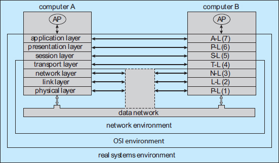
Figure 17.5 Two computers communicating via the OSI network model.
- Layer 1: Physical layer. The physical layer is responsible for handling both the mechanical and the electrical details of the physical transmission of a bit stream. At the physical layer, the communicating systems must agree on the electrical representation of a binary 0 and 1, so that when data are sent as a stream of electrical signals, the receiver is able to interpret the data properly as binary data. This layer is implemented in the hardware of the networking device. It is responsible for delivering bits.
- Layer 2: Data-link layer. The data-link layer is responsible for handling frames, or fixed-length parts of packets, including any error detection and recovery that occurs in the physical layer. It sends frames between physical addresses.
- Layer 3: Network layer. The network layer is responsible for breaking messages into packets, providing connections between logical addresses, and routing packets in the communication network, including handling the addresses of outgoing packets, decoding the addresses of incoming packets, and maintaining routing information for proper response to changing load levels. Routers work at this layer.
- Layer 4: Transport layer. The transport layer is responsible for transfer of messages between nodes, including partitioning messages into packets, maintaining packet order, and controlling flow to avoid congestion.
- Layer 5: Session layer. The session layer is responsible for implementing sessions, or process-to-process communication protocols.
- Layer 6: Presentation layer. The presentation layer is responsible for resolving the differences in formats among the various sites in the network, including character conversions and half duplex–full duplex modes (character echoing).
- Layer 7: Application layer. The application layer is responsible for interacting directly with users. This layer deals with file transfer, remote-login protocols, and electronic mail, as well as with schemas for distributed databases.
Figure 17.6 summarizes the OSI protocol stack—a set of cooperating protocols—showing the physical flow of data. As mentioned, logically each layer of a protocol stack communicates with the equivalent layer on other systems. But physically, a message starts at or above the application layer and is passed through each lower level in turn. Each layer may modify the message and include message-header data for the equivalent layer on the receiving side. Ultimately, the message reaches the data-network layer and is transferred as one or more packets (Figure 17.7). The data-link layer of the target system receives these data, and the message is moved up through the protocol stack. It is analyzed, modified, and stripped of headers as it progresses. It finally reaches the application layer for use by the receiving process.
The OSI model formalizes some of the earlier work done in network protocols but was developed in the late 1970s and is currently not in widespread use. Perhaps the most widely adopted protocol stack is the TCP/IP model, which has been adopted by virtually all Internet sites. The TCP/IP protocol stack has fewer layers than the OSI model. Theoretically, because it combines several functions in each layer, it is more difficult to implement but more efficient than OSI networking. The relationship between the OSI and TCP/IP models is shown in Figure 17.8.
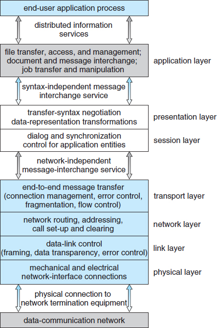
Figure 17.6 The OSI protocol stack.
The TCP/IP application layer identifies several protocols in widespread use in the Internet, including HTTP, FTP, Telnet, ssh, DNS, and SMTP. The transport layer identifies the unreliable, connectionless user datagram protocol (UDP) and the reliable, connection-oriented transmission control protocol (TCP). The Internet protocol (IP) is responsible for routing IP datagrams through the Internet. The TCP/IP model does not formally identify a link or physical layer, allowing TCP/IP traffic to run across any physical network. In Section 17.6, we consider the TCP/IP model running over an Ethernet network.
Security should be a concern in the design and implementation of any modern communication protocol. Both strong authentication and encryption are needed for secure communication. Strong authentication ensures that the sender and receiver of a communication are who or what they are supposed to be. Encryption protects the contents of the communication from eavesdropping. Weak authentication and clear-text communication are still very common, however, for a variety of reasons. When most of the common protocols were designed, security was frequently less important than performance, simplicity, and efficiency. This legacy is still showing itself today, as adding security to existing infrastructure is proving to be difficult and complex.

Figure 17.7 An OSI network message.

Figure 17.8 The OSI and TCP/IP protocol stacks.
Strong authentication requires a multistep handshake protocol or authentication devices, adding complexity to a protocol. Modern CPUs can efficiently perform encryption, frequently including cryptographic acceleration instructions, so system performance is not compromised. Long-distance communication can be made secure by authenticating the endpoints and encrypting the stream of packets in a virtual private network, as discussed in Section 15.4.2. LAN communication remains unencrypted at most sites, but protocols such as NFS Version 4, which includes strong native authentication and encryption, should help improve even LAN security.
17.6 An Example: TCP/IP
We now return to the name-resolution issue raised in Section 17.4.1 and examine its operation with respect to the TCP/IP protocol stack on the Internet. Then we consider the processing needed to transfer a packet between hosts on different Ethernet networks. We base our description on the IPV4 protocols, which are the type most commonly used today.
In a TCP/IP network, every host has a name and an associated IP address (or host-id). Both of these strings must be unique; and so that the name space can be managed, they are segmented. The name is hierarchical (as explained in Section 17.4.1), describing the host name and then the organization with which the host is associated. The host-id is split into a network number and a host number. The proportion of the split varies, depending on the size of the network. Once the Internet administrators assign a network number, the site with that number is free to assign host-ids.
The sending system checks its routing tables to locate a router to send the frame on its way. The routers use the network part of the host-id to transfer the packet from its source network to the destination network. The destination system then receives the packet. The packet may be a complete message, or it may just be a component of a message, with more packets needed before the message can be reassembled and passed to the TCP/UDP layer for transmission to the destination process.
Within a network, how does a packet move from sender (host or router) to receiver? Every Ethernet device has a unique byte number, called the medium access control (MAC) address, assigned to it for addressing. Two devices on a LAN communicate with each other only with this number. If a system needs to send data to another system, the networking software generates an address resolution protocol (ARP) packet containing the IP address of the destination system. This packet is broadcast to all other systems on that Ethernet network.
A broadcast uses a special network address (usually, the maximum address) to signal that all hosts should receive and process the packet. The broadcast is not re-sent by gateways, so only systems on the local network receive it. Only the system whose IP address matches the IP address of the ARP request responds and sends back its MAC address to the system that initiated the query. For efficiency, the host caches the IP– MAC address pair in an internal table. The cache entries are aged, so that an entry is eventually removed from the cache if an access to that system is not required within a given time. In this way, hosts that are removed from a network are eventually forgotten. For added performance, ARP entries for heavily used hosts may be pinned in the ARP cache.

Figure 17.9 An Ethernet packet.
Once an Ethernet device has announced its host-id and address, communication can begin. A process may specify the name of a host with which to communicate. Networking software takes that name and determines the IP address of the target, using a DNS lookup. The message is passed from the application layer, through the software layers, and to the hardware layer. At the hardware layer, the packet (or packets) has the Ethernet address at its start; a trailer indicates the end of the packet and contains a checksum for detection of packet damage (Figure 17.9). The packet is placed on the network by the Ethernet device. The data section of the packet may contain some or all of the data of the original message, but it may also contain some of the upper-level headers that compose the message. In other words, all parts of the original message must be sent from source to destination, and all headers above the 802.3 layer (data-link layer) are included as data in the Ethernet packets.
If the destination is on the same local network as the source, the system can look in its ARP cache, find the Ethernet address of the host, and place the packet on the wire. The destination Ethernet device then sees its address in the packet and reads in the packet, passing it up the protocol stack.
If the destination system is on a network different from that of the source, the source system finds an appropriate router on its network and sends the packet there. Routers then pass the packet along the WAN until it reaches its destination network. The router that connects the destination network checks its ARP cache, finds the Ethernet number of the destination, and sends the packet to that host. Through all of these transfers, the data-link-layer header may change as the Ethernet address of the next router in the chain is used, but the other headers of the packet remain the same until the packet is received and processed by the protocol stack and finally passed to the receiving process by the kernel.
17.7 Robustness
A distributed system may suffer from various types of hardware failure. The failure of a link, the failure of a site, and the loss of a message are the most common types. To ensure that the system is robust, we must detect any of these failures, reconfigure the system so that computation can continue, and recover when a site or a link is repaired.
17.7.1 Failure Detection
In an environment with no shared memory, we are generally unable to differentiate among link failure, site failure, and message loss. We can usually detect only that one of these failures has occurred. Once a failure has been detected, appropriate action must be taken. What action is appropriate depends on the particular application.
To detect link and site failure, we use a heartbeat procedure. Suppose that sites A and B have a direct physical link between them. At fixed intervals, the sites send each other an I-am-up message. If site A does not receive this message within a predetermined time period, it can assume that site B has failed, that the link between A and B has failed, or that the message from B has been lost. At this point, site A has two choices. It can wait for another time period to receive an I-am-up message from B, or it can send an Are-you-up? message to B.
If time goes by and site A still has not received an I-am-up message, or if site A has sent an Are-you-up? message and has not received a reply, the procedure can be repeated. Again, the only conclusion that site A can draw safely is that some type of failure has occurred.
Site A can try to differentiate between link failure and site failure by sending an Are-you-up? message to B by another route (if one exists). If and when B receives this message, it immediately replies positively. This positive reply tells A that B is up and that the failure is in the direct link between them. Since we do not know in advance how long it will take the message to travel from A to B and back, we must use a time-out scheme. At the time A sends the Are-you-up? message, it specifies a time interval during which it is willing to wait for the reply from B. If A receives the reply message within that time interval, then it can safely conclude that B is up. If not, however (that is, if a time-out occurs), then A may conclude only that one or more of the following situations has occurred:
- Site B is down.
- The direct link (if one exists) from A to B is down.
- The alternative path from A to B is down.
- The message has been lost.
Site A cannot, however, determine which of these events has occurred.
17.7.2 Reconfiguration
Suppose that site A has discovered, through the mechanism just described, that a failure has occurred. It must then initiate a procedure that will allow the system to reconfigure and to continue its normal mode of operation.
- If a direct link from A to B has failed, this information must be broadcast to every site in the system, so that the various routing tables can be updated accordingly.
- If the system believes that a site has failed (because that site can be reached no longer), then all sites in the system must be notified, so that they will no longer attempt to use the services of the failed site. The failure of a site that serves as a central coordinator for some activity (such as deadlock detection) requires the election of a new coordinator. Similarly, if the failed site is part of a logical ring, then a new logical ring must be constructed. Note that, if the site has not failed (that is, if it is up but cannot be reached), then we may have the undesirable situation in which two sites serve as the coordinator. When the network is partitioned, the two coordinators (each for its own partition) may initiate conflicting actions. For example, if the coordinators are responsible for implementing mutual exclusion, we may have a situation in which two processes are executing simultaneously in their critical sections.
17.7.3 Recovery from Failure
When a failed link or site is repaired, it must be integrated into the system gracefully and smoothly.
- Suppose that a link between A and B has failed. When it is repaired, both A and B must be notified. We can accomplish this notification by continuously repeating the heartbeat procedure described in Section 17.7.1.
- Suppose that site B has failed. When it recovers, it must notify all other sites that it is up again. Site B then may have to receive information from the other sites to update its local tables. For example, it may need routing-table information, a list of sites that are down, undelivered messages, a transaction log of unexecuted transactions, and mail. If the site has not failed but simply could not be reached, then it still needs this information.
17.7.4 Fault Tolerance
A distributed system must tolerate a certain level of failure and continue to function normally when faced with various types of failures. Making a facility fault tolerant starts at the protocol level, as described above, but continues through all aspects of the system. We use the term fault tolerance in a broad sense. Communication faults, certain machine failures, storage-device crashes, and decays of storage media should all be tolerated to some extent. A fault-tolerant system should continue to function, perhaps in a degraded form, when faced with such failures. The degradation can affect performance, functionality, or both. It should be proportional, however, to the failures that caused it. A system that grinds to a halt when only one of its components fails is certainly not fault tolerant.
Unfortunately, fault tolerance can be difficult and expensive to implement. At the network layer, multiple redundant communication paths and network devices such as switches and routers are needed to avoid a communication failure. A storage failure can cause loss of the operating system, applications, or data. Storage units can include redundant hardware components that automatically take over from each other in case of failure. In addition, RAID systems can ensure continued access to the data even in the event of one or more disk failures (Section 10.7).
A system failure without redundancy can cause an application or an entire facility to stop operation. The most simple system failure involves a system running only stateless applications. These applications can be restarted without compromising the operation; so as long as the applications can run on more than one computer (node), operation can continue. Such a facility is commonly known as a compute cluster because it centers on computation.
In contrast, datacentric systems involve running applications that access and modify shared data. As a result, datacentric computing facilities are more difficult to make fault tolerant. They require failure-monitoring software and special infrastructure. For instance, high-availability clusters include two or more computers and a set of shared disks. Any given application can be stored on the computers or on the shared disk, but the data must be stored on the shared disk. The running application's node has exclusive access to the application's data on disk. The application is monitored by the cluster software, and if it fails it is automatically restarted. If it cannot be restarted, or if the entire computer fails, the node's exclusive access to the application's data is terminated and is granted to another node in the cluster. The application is restarted on that new node. The application loses whatever state information was in the failed system's memory but can continue based on whatever state it last wrote to the shared disk. From a user's point of view, a service was interrupted and then restarted, possibly with some data missing.
Specific applications may improve on this functionality by implementing lock management along with clustering. With lock management, the application can run on multiple nodes and can use the same data on shared disks concurrently. Clustered databases frequently implement this functionality. If a node fails, transactions can continue on other nodes, and users notice no interruption of service, as long as the client is able to automatically locate the other nodes in the cluster. Any noncommitted transactions on the failed node are lost, but again, client applications can be designed to retry noncommitted transactions if they detect a failure of their database node.
17.8 Design Issues
Making the multiplicity of processors and storage devices transparent to the users has been a key challenge to many designers. Ideally, a distributed system should look to its users like a conventional, centralized system. The user interface of a transparent distributed system should not distinguish between local and remote resources. That is, users should be able to access remote resources as though these resources were local, and the distributed system should be responsible for locating the resources and for arranging for the appropriate interaction.
Another aspect of transparency is user mobility. It would be convenient to allow users to log into any machine in the system rather than forcing them to use a specific machine. A transparent distributed system facilitates user mobility by bringing over the user's environment (for example, home directory) to wherever he logs in. Protocols like LDAP provide an authentication system for local, remote, and mobile users. Once the authentication is complete, facilities like desktop virtualization allow users to see their desktop sessions at remote facilities.
Still another issue is scalability—the capability of a system to adapt to increased service load. Systems have bounded resources and can become completely saturated under increased load. For example, with respect to a file system, saturation occurs either when a server's CPU runs at a high utilization rate or when disks' I/O requests overwhelm the I/O subsystem. Scalability is a relative property, but it can be measured accurately. A scalable system reacts more gracefully to increased load than does a nonscalable one. First, its performance degrades more moderately; and second, its resources reach a saturated state later. Even perfect design cannot accommodate an ever-growing load. Adding new resources might solve the problem, but it might generate additional indirect load on other resources (for example, adding machines to a distributed system can clog the network and increase service loads). Even worse, expanding the system can call for expensive design modifications. A scalable system should have the potential to grow without these problems. In a distributed system, the ability to scale up gracefully is of special importance, since expanding the network by adding new machines or interconnecting two networks is commonplace. In short, a scalable design should withstand high service load, accommodate growth of the user community, and allow simple integration of added resources.
Scalability is related to fault tolerance, discussed earlier. A heavily loaded component can become paralyzed and behave like a faulty component. In addition, shifting the load from a faulty component to that component's backup can saturate the latter. Generally, having spare resources is essential for ensuring reliability as well as for handling peak loads gracefully. Thus, the multiple resources in a distributed system represent an inherent advantage, giving the system a greater potential for fault tolerance and scalability. However, inappropriate design can obscure this potential. Fault-tolerance and scalability considerations call for a design demonstrating distribution of control and data.
Facilities like the Hadoop distributed file system were created with this problem in mind. Hadoop is based on Google's MapReduce and Google File System projects that created a facility to track every web page on the Internet. Hadoop is an open-source programming framework that supports the processing of large data sets in distributed computing environments. Traditional systems with traditional databases cannot scale to the capacity and performance needed by “big data” projects (at least not at reasonable prices). Examples of big data projects include mining Twitter for information pertinent to a company and sifting financial data to look for trends in stock pricing. With Hadoop and its related tools, thousands of systems can work together to manage a distributed database of petabytes of information.
17.9 Distributed File Systems
Although the World Wide Web is the predominant distributed system in use today, it is not the only one. Another important and popular use of distributed computing is the distributed file system, or DFS. In this section, we discuss distributed file systems. In doing so, we use two running examples—OpenAFS, an open-source distributed file system, and NFS, the most common UNIX-based DFS. NFS has several versions, and here we refer to NFS Version 3 unless otherwise noted.
To explain the structure of a DFS, we need to define the terms service, server, and client in the DFS context. A service is a software entity running on one or more machines and providing a particular type of function to clients. A server is the service software running on a single machine. A client is a process that can invoke a service using a set of operations that form its client interface. Sometimes a lower-level interface is defined for the actual cross-machine interaction; it is the intermachine interface.
Using this terminology, we say that a file system provides file services to clients. A client interface for a file service is formed by a set of primitive file operations, such as create a file, delete a file, read from a file, and write to a file. The primary hardware component that a file server controls is a set of local secondary-storage devices (usually, magnetic disks) on which files are stored and from which they are retrieved according to the clients’ requests.
A DFS is a file system whose clients, servers, and storage devices are dispersed among the machines of a distributed system. Accordingly, service activity has to be carried out across the network. Instead of a single centralized data repository, the system frequently has multiple and independent storage devices. As you will see, the concrete configuration and implementation of a DFS may vary from system to system. In some configurations, servers run on dedicated machines. In others, a machine can be both a server and a client. A DFS can be implemented as part of a distributed operating system or, alternatively, by a software layer whose task is to manage the communication between conventional operating systems and file systems.
The distinctive features of a DFS are the multiplicity and autonomy of clients and servers in the system. Ideally, though, a DFS should appear to its clients to be a conventional, centralized file system. That is, the client interface of a DFS should not distinguish between local and remote files. It is up to the DFS to locate the files and to arrange for the transport of the data. A transparent DFS—like the transparent distributed systems mentioned earlier—facilitates user mobility by bringing a user's environment (that is, home directory) to wherever the user logs in.
The most important performance measure of a DFS is the amount of time needed to satisfy service requests. In conventional systems, this time consists of disk-access time and a small amount of CPU-processing time. In a DFS, however, a remote access has the additional overhead associated with the distributed structure. This overhead includes the time to deliver the request to a server, as well as the time to get the response across the network back to the client. For each direction, in addition to the transfer of the information, there is the CPU overhead of running the communication protocol software. The performance of a DFS can be viewed as another dimension of the DFS's transparency. That is, the performance of an ideal DFS would be comparable to that of a conventional file system.
The fact that a DFS manages a set of dispersed storage devices is the DFS's key distinguishing feature. The overall storage space managed by a DFS is composed of different and remotely located smaller storage spaces. Usually, these constituent storage spaces correspond to sets of files. A component unit is the smallest set of files that can be stored on a single machine, independently from other units. All files belonging to the same component unit must reside in the same location.
17.9.1 Naming and Transparency
Naming is a mapping between logical and physical objects. For instance, users deal with logical data objects represented by file names, whereas the system manipulates physical blocks of data stored on disk tracks. Usually, a user refers to a file by a textual name. The latter is mapped to a lower-level numerical identifier that in turn is mapped to disk blocks. This multilevel mapping provides users with an abstraction of a file that hides the details of how and where on the disk the file is stored.
In a transparent DFS, a new dimension is added to the abstraction: that of hiding where in the network the file is located. In a conventional file system, the range of the naming mapping is an address within a disk. In a DFS, this range is expanded to include the specific machine on whose disk the file is stored. Going one step further with the concept of treating files as abstractions leads to the possibility of file replication. Given a file name, the mapping returns a set of the locations of this file's replicas. In this abstraction, both the existence of multiple copies and their locations are hidden.
17.9.1.1 Naming Structures
We need to differentiate two related notions regarding name mappings in a DFS:
- Location transparency. The name of a file does not reveal any hint of the file's physical storage location.
- Location independence. The name of a file does not need to be changed when the file's physical storage location changes.
Both definitions relate to the level of naming discussed previously, since files have different names at different levels (that is, user-level textual names and system-level numerical identifiers). A location-independent naming scheme is a dynamic mapping, since it can map the same file name to different locations at two different times. Therefore, location independence is a stronger property than is location transparency.
In practice, most of the current DFSs provide a static, location-transparent mapping for user-level names. Some support file migration—that is, changing the location of a file automatically, providing location independence. OpenAFS supports location independence and file mobility, for example. The Hadoop distributed file system (HDFS)—a special file system written for the Hadoop framework—is a more recent creation. It includes file migration but does so without following POSIX standards, providing more flexibility in implementation and interface. HDFS keeps track of the location of data but hides this information from clients. This dynamic location transparency allows the underlying mechanism to self-tune. In another example, Amazon's §3 cloud storage facility provides blocks of storage on demand via APIs, placing the storage where it sees fit and moving the data as necessary to meet performance, reliability, and capacity requirements.
A few aspects can further differentiate location independence and static location transparency:
- Divorce of data from location, as exhibited by location independence, provides a better abstraction for files. A file name should denote the file's most significant attributes, which are its contents rather than its location. Location-independent files can be viewed as logical data containers that are not attached to a specific storage location. If only static location transparency is supported, the file name still denotes a specific, although hidden, set of physical disk blocks.
- Static location transparency provides users with a convenient way to share data. Users can share remote files by simply naming the files in a location-transparent manner, as though the files were local. Dropbox and other cloud-based storage solutions work this way. Location independence promotes sharing the storage space itself, as well as the data objects. When files can be mobilized, the overall, system-wide storage space looks like a single virtual resource. A possible benefit is the ability to balance the utilization of storage across the system.
- Location independence separates the naming hierarchy from the storage-devices hierarchy and from the intercomputer structure. By contrast, if static location transparency is used (although names are transparent), we can easily expose the correspondence between component units and machines. The machines are configured in a pattern similar to the naming structure. This configuration may restrict the architecture of the system unnecessarily and conflict with other considerations. A server in charge of a root directory is an example of a structure that is dictated by the naming hierarchy and contradicts decentralization guidelines.
Once the separation of name and location has been completed, clients can access files residing on remote server systems. In fact, these clients may be diskless and rely on servers to provide all files, including the operating-system kernel. Special protocols are needed for the boot sequence, however. Consider the problem of getting the kernel to a diskless workstation. The diskless workstation has no kernel, so it cannot use the DFS code to retrieve the kernel. Instead, a special boot protocol, stored in read-only memory (ROM) on the client, is invoked. It enables networking and retrieves only one special file (the kernel or boot code) from a fixed location. Once the kernel is copied over the network and loaded, its DFS makes all the other operating-system files available. The advantages of diskless clients are many, including lower cost (because the client machines require no disks) and greater convenience (when an operating-system upgrade occurs, only the server needs to be modified). The disadvantages are the added complexity of the boot protocols and the performance loss resulting from the use of a network rather than a local disk.
17.9.1.2 Naming Schemes
There are three main approaches to naming schemes in a DFS. In the simplest approach, a file is identified by some combination of its host name and local name, which guarantees a unique system-wide name. In Ibis, for instance, a file is identified uniquely by the name host:local-name, where local-name is a UNIX-like path. The Internet URL system also uses this approach. This naming scheme is neither location transparent nor location independent. The DFS is structured as a collection of isolated component units, each of which is an entire conventional file system. Component units remain isolated, although means are provided to refer to remote files. We do not consider this scheme any further here.
The second approach was popularized by Sun's network file system, NFS. NFS is found in many systems, including UNIX and Linux distributions. NFS provides a means to attach remote directories to local directories, thus giving the appearance of a coherent directory tree. Early NFS versions allowed only previously mounted remote directories to be accessed transparently. The advent of the automount feature allowed mounts to be done on demand based on a table of mount points and file-structure names. Components are integrated to support transparent sharing, but this integration is limited and is not uniform, because each machine may attach different remote directories to its tree. The resulting structure is versatile.
We can achieve total integration of the component file systems by using the third approach. Here, a single global name structure spans all the files in the system. Ideally, the composed file-system structure is the same as the structure of a conventional file system. In practice, however, the many special files (for example, UNIX device files and machine-specific binary directories) make this goal difficult to attain. To evaluate naming structures, we look at their administrative complexity. The most complex and most difficult-to-maintain structure is the NFS structure. Because any remote directory can be attached anywhere onto the local directory tree, the resulting hierarchy can be highly unstructured. If a server becomes unavailable, some arbitrary set of directories on different machines becomes unavailable. In addition, a separate accreditation mechanism controls which machine is allowed to attach which directory to its tree. Thus, a user might be able to access a remote directory tree on one client but be denied access on another client.
17.9.1.3 Implementation Techniques
Implementation of transparent naming requires a provision for the mapping of a file name to the associated location. To keep this mapping manageable, we must aggregate sets of files into component units and provide the mapping on a component-unit basis rather than on a single-file basis. This aggregation serves administrative purposes as well. UNIX-like systems use the hierarchical directory tree to provide name-to-location mapping and to aggregate files recursively into directories.
To enhance the availability of the crucial mapping information, we can use replication, local caching, or both. As we noted, location independence means that the mapping changes over time. Hence, replicating the mapping makes a simple yet consistent update of this information impossible. To overcome this obstacle, we can introduce low-level, location-independent file identifiers. (OpenAFS uses this approach.) Textual file names are mapped to lower-level file identifiers that indicate to which component unit the file belongs. These identifiers are still location independent. They can be replicated and cached freely without being invalidated by migration of component units. The inevitable price is the need for a second level of mapping, which maps component units to locations and needs a simple yet consistent update mechanism. Implementing UNIX-like directory trees using these low-level, location-independent identifiers makes the whole hierarchy invariant under component-unit migration. The only aspect that does change is the component-unit location mapping.
A common way to implement low-level identifiers is to use structured names. These names are bit strings that usually have two parts. The first part identifies the component unit to which the file belongs; the second part identifies the particular file within the unit. Variants with more parts are possible. The invariant of structured names, however, is that individual parts of the name are unique at all times only within the context of the rest of the parts. We can obtain uniqueness at all times by taking care not to reuse a name that is still in use, by adding sufficiently more bits (this method is used in OpenAFS), or by using a timestamp as one part of the name (as was done in Apollo Domain). Another way to view this process is that we are taking a location-transparent system, such as Ibis, and adding another level of abstraction to produce a location-independent naming scheme.
17.9.2 Remote File Access
Next, let's consider a user who requests access to a remote file. The server storing the file has been located by the naming scheme, and now the actual data transfer must take place.
One way to achieve this transfer is through a remote-service mechanism, whereby requests for accesses are delivered to the server, the server machine performs the accesses, and their results are forwarded back to the user. One of the most common ways of implementing remote service is the RPC paradigm, which we discussed in Chapter 3. A direct analogy exists between disk-access methods in conventional file systems and the remote-service method in a DFS: using the remote-service method is analogous to performing a disk access for each access request.
To ensure reasonable performance of a remote-service mechanism, we can use a form of caching. In conventional file systems, the rationale for caching is to reduce disk I/O (thereby increasing performance), whereas in DFSs, the goal is to reduce both network traffic and disk I/O. In the following discussion, we describe the implementation of caching in a DFS and contrast it with the basic remote-service paradigm.
17.9.2.1 Basic Caching Scheme
The concept of caching is simple. If the data needed to satisfy the access request are not already cached, then a copy of those data is brought from the server to the client system. Accesses are performed on the cached copy. The idea is to retain recently accessed disk blocks in the cache, so that repeated accesses to the same information can be handled locally, without additional network traffic. A replacement policy (for example, the least-recently-used algorithm) keeps the cache size bounded. No direct correspondence exists between accesses and traffic to the server. Files are still identified with one master copy residing at the server machine, but copies (or parts) of the file are scattered in different caches. When a cached copy is modified, the changes need to be reflected on the master copy to preserve the relevant consistency semantics. The problem of keeping the cached copies consistent with the master file is the cache-consistency problem, which we discuss in Section 17.9.2.4. DFS caching could just as easily be called network virtual memory. It acts similarly to demand-paged virtual memory, except that the backing store usually is a remote server rather than a local disk. NFS allows the swap space to be mounted remotely, so it actually can implement virtual memory over a network, though with a resulting performance penalty.
The granularity of the cached data in a DFS can vary from blocks of a file to an entire file. Usually, more data are cached than are needed to satisfy a single access, so that many accesses can be served by the cached data. This procedure is much like disk read-ahead (Section 12.6.2). OpenAFS caches files in large chunks (64 KB). The other systems discussed here support caching of individual blocks driven by client demand. Increasing the caching unit increases the hit ratio, but it also increases the miss penalty, because each miss requires more data to be transferred. It increases the potential for consistency problems as well. Selecting the unit of caching involves considering parameters such as the network transfer unit and the RPC protocol service unit (if an RPC protocol is used). The network transfer unit (for Ethernet, a packet) is about 1.5 KB, so larger units of cached data need to be disassembled for delivery and reassembled on reception.
Block size and total cache size are obviously of importance for block-caching schemes. In UNIX-like systems, common block sizes are 4 KB and 8 KB. For large caches (over 1 MB), large block sizes (over 8 KB) are beneficial. For smaller caches, large block sizes are less beneficial because they result in fewer blocks in the cache and a lower hit ratio.
17.9.2.2 Cache Location
Where should the cached data be stored—on disk or in main memory? Disk caches have one clear advantage over main-memory caches: they are reliable. Modifications to cached data are lost in a crash if the cache is kept in volatile memory. Moreover, if the cached data are kept on disk, they are still there during recovery, and there is no need to fetch them again. Main-memory caches have several advantages of their own, however:
- Main-memory caches permit workstations to be diskless.
- Data can be accessed more quickly from a cache in main memory than from one on a disk.
- Technology is moving toward larger and less expensive memory. The resulting performance speedup is predicted to outweigh the advantages of disk caches.
- The server caches (used to speed up disk I/O) will be in main memory regardless of where user caches are located; if we use main-memory caches on the user machine, too, we can build a single caching mechanism for use by both servers and users.
Many remote-access implementations can be thought of as hybrids of caching and remote service. In NFS, for instance, the implementation is based on remote service but is augmented with client- and server-side memory caching for performance. Similarly, Sprite's implementation is based on caching, but under certain circumstances, a remote-service method is adopted. Thus, to evaluate the two methods, we must evaluate the degree to which either method is emphasized. The NFS protocol and most implementations do not provide disk caching.
17.9.2.3 Cache-Update Policy
The policy used to write modified data blocks back to the server's master copy has a critical effect on the system's performance and reliability. The simplest policy is to write data through to disk as soon as they are placed in any cache. The advantage of a write-through policy is reliability: little information is lost when a client system crashes. However, this policy requires each write access to wait until the information is sent to the server, so it causes poor write performance. Caching with write-through is equivalent to using remote service for write accesses and exploiting caching only for read accesses.
An alternative is the delayed-write policy, also known as write-back caching, where we delay updates to the master copy. Modifications are written to the cache and then are written through to the server at a later time. This policy has two advantages over write-through. First, because writes are made to the cache, write accesses complete much more quickly. Second, data may be overwritten before they are written back, in which case only the last update needs to be written at all. Unfortunately, delayed-write schemes introduce reliability problems, since unwritten data are lost whenever a user machine crashes.
Variations of the delayed-write policy differ in when modified data blocks are flushed to the server. One alternative is to flush a block when it is about to be ejected from the client's cache. This option can result in good performance, but some blocks can reside in the client's cache a long time before they are written back to the server. A compromise between this alternative and the write-through policy is to scan the cache at regular intervals and to flush blocks that have been modified since the most recent scan, just as UNIX scans its local cache. Sprite uses this policy with a 30-second interval. NFS uses the policy for file data, but once a write is issued to the server during a cache flush, the write must reach the server's disk before it is considered complete. NFS treats metadata (directory data and file-attribute data) differently. Any metadata changes are issued synchronously to the server. Thus, file-structure loss and directory-structure corruption are avoided when a client or the server crashes.
Yet another variation on delayed write is to write data back to the server when the file is closed. This write-on-close policy is used in OpenAFS. In the case of files that are open for short periods or are modified rarely, this policy does not significantly reduce network traffic. In addition, the write-on-close policy requires the closing process to delay while the file is written through, which reduces the performance advantages of delayed writes. For files that are open for long periods and are modified frequently, however, the performance advantages of this policy over delayed write with more frequent flushing are apparent.
17.9.2.4 Consistency
A client machine is sometimes faced with the problem of deciding whether a locally cached copy of data is consistent with the master copy (and hence can be used). If the client machine determines that its cached data are out of date, it must cache an up-to-date copy of the data before allowing further accesses. There are two approaches to verifying the validity of cached data:
- Client-initiated approach. The client initiates a validity check, in which it contacts the server and checks whether the local data are consistent with the master copy. The frequency of the validity checking is the crux of this approach and determines the resulting consistency semantics. It can range from a check before every access to a check only on first access to a file (on file open, basically). Every access coupled with a validity check is delayed, compared with an access served immediately by the cache. Alternatively, checks can be initiated at fixed time intervals. Depending on its frequency, the validity check can load both the network and the server.
- Server-initiated approach. The server records, for each client, the files (or parts of files) that it caches. When the server detects a potential inconsistency, it must react. A potential for inconsistency occurs when two different clients in conflicting modes cache a file. If UNIX semantics (Section 11.5.3) is implemented, we can resolve the potential inconsistency by having the server play an active role. The server must be notified whenever a file is opened, and the intended mode (read or write) must be indicated for every open. The server can then act when it detects that a file has been opened simultaneously in conflicting modes by disabling caching for that particular file. Actually, disabling caching results in switching to a remote-service mode of operation.
Distributed file systems are in common use today, providing file sharing within LANs and across WANs as well. The complexity of implementing such a system should not be underestimated, especially considering that it must be operating-system independent for widespread adoption and must provide availability and good performance in the presence of long distances and sometimes-frail networking.
17.10 Summary
A distributed system is a collection of processors that do not share memory or a clock. Instead, each processor has its own local memory, and the processors communicate with one another through various communication lines, such as high-speed buses and the Internet. The processors in a distributed system vary in size and function. They may include small microprocessors, personal computers, and large general-purpose computer systems. The processors in the system are connected through a communication network.
A distributed system provides the user with access to all system resources. Access to a shared resource can be provided by data migration, computation migration, or process migration. The access can be specified by the user or implicitly supplied by the operating system and applications.
Communications within a distributed system may occur via circuit switching, message switching, or packet switching. Packet switching is the method most commonly used on data networks. Through these methods, messages can be exchanged by nodes in the system.
Protocol stacks, as specified by network layering models, add information to a message to ensure that it reaches its destination. A naming system (such as DNS) must be used to translate from a host name to a network address, and another protocol (such as ARP) may be needed to translate the network number to a network device address (an Ethernet address, for instance). If systems are located on separate networks, routers are needed to pass packets from source network to destination network.
There are many challenges to overcome for a distributed system to work correctly. Issues include naming of nodes and processes in the system, fault tolerance, error recovery, and scalability.
A DFS is a file-service system whose clients, servers, and storage devices are dispersed among the sites of a distributed system. Accordingly, service activity has to be carried out across the network; instead of a single centralized data repository, there are multiple independent storage devices.
Ideally, a DFS should look to its clients like a conventional, centralized file system. The multiplicity and dispersion of its servers and storage devices should be transparent. A transparent DFS facilitates client mobility by bringing the client's environment to the site where the client logs in.
There are several approaches to naming schemes in a DFS. In the simplest approach, files are named by some combination of their host name and local name, which guarantees a unique system-wide name. Another approach, popularized by NFS, provides a means to attach remote directories to local directories, thus giving the appearance of a coherent directory tree.
Requests to access a remote file are usually handled by two complementary methods. With remote service, requests for accesses are delivered to the server. The server machine performs the accesses, and the results are forwarded back to the client. With caching, if the data needed to satisfy the access request are not already cached, then a copy of the data is brought from the server to the client. Accesses are performed on the cached copy. The problem of keeping the cached copies consistent with the master file is the cache-consistency problem.
Practice Exercises
17.1 Why would it be a bad idea for gateways to pass broadcast packets between networks? What would be the advantages of doing so?
17.2 Discuss the advantages and disadvantages of caching name translations for computers located in remote domains.
17.3 What are the advantages and disadvantages of using circuit switching? For what kinds of applications is circuit switching a viable strategy?
17.4 What are two formidable problems that designers must solve to implement a network system that has the quality of transparency?
17.5 Process migration within a heterogeneous network is usually impossible, given the differences in architectures and operating systems. Describe a method for process migration across different architectures running:
- The same operating system
- Different operating systems
17.6 To build a robust distributed system, you must know what kinds of failures can occur.
- List three possible types of failure in a distributed system.
- Specify which of the entries in your list also are applicable to a centralized system.
17.7 Is it always crucial to know that the message you have sent has arrived at its destination safely? If your answer is “yes,” explain why. If your answer is “no,” give appropriate examples.
17.8 A distributed system has two sites, A and B. Consider whether site A can distinguish among the following:
- B goes down.
- The link between A and B goes down.
- B is extremely overloaded, and its response time is 100 times longer than normal.
What implications does your answer have for recovery in distributed systems?
Exercises
17.9 What is the difference between computation migration and process migration? Which is easier to implement, and why?
17.10 Even though the OSI model of networking specifies seven layers of functionality, most computer systems use fewer layers to implement a network. Why do they use fewer layers? What problems could the use of fewer layers cause?
17.11 Explain why doubling the speed of the systems on an Ethernet segment may result in decreased network performance. What changes could help solve this problem?
17.12 What are the advantages of using dedicated hardware devices for routers and gateways? What are the disadvantages of using these devices compared with using general-purpose computers?
17.13 In what ways is using a name server better than using static host tables? What problems or complications are associated with name servers? What methods could you use to decrease the amount of traffic name servers generate to satisfy translation requests?
17.14 Name servers are organized in a hierarchical manner. What is the purpose of using a hierarchical organization?
17.15 The lower layers of the OSI network model provide datagram service, with no delivery guarantees for messages. A transport-layer protocol such as TCP is used to provide reliability. Discuss the advantages and disadvantages of supporting reliable message delivery at the lowest possible layer.
17.16 How does using a dynamic routing strategy affect application behavior? For what type of applications is it beneficial to use virtual routing instead of dynamic routing?
17.17 Run the program shown in Figure 17.4 and determine the IP addresses of the following host names:
17.18 The original HTTP protocol used TCP/IP as the underlying network protocol. For each page, graphic, or applet, a separate TCP session was constructed, used, and torn down. Because of the overhead of building and destroying TCP/IP connections, performance problems resulted from this implementation method. Would using UDP rather than TCP be a good alternative? What other changes could you make to improve HTTP performance?
17.19 What are the advantages and the disadvantages of making the computer network transparent to the user?
17.20 What are the benefits of a DFS compared with a file system in a centralized system?
17.21 Which of the example DFSs discussed in this chapter would handle a large, multiclient database application most efficiently? Explain your answer.
17.22 Discuss whether OpenAFS and NFS provide the following: (a) location transparency and (b) location independence.
17.23 Under what circumstances would a client prefer a location-transparent DFS? Under what circumstances would she prefer a location-independent DFS? Discuss the reasons for these preferences.
17.24 What aspects of a distributed system would you select for a system running on a totally reliable network?
17.25 Consider OpenAFS, which is a stateful distributed file system. What actions need to be performed to recover from a server crash in order to preserve the consistency guaranteed by the system?
17.26 Compare and contrast the techniques of caching disk blocks locally, on a client system, and remotely, on a server.
17.27 OpenAFS is designed to support a large number of clients. Discuss three techniques used to make OpenAFS a scalable system.
17.28 What are the benefits of mapping objects into virtual memory, as Apollo Domain does? What are the drawbacks?
17.29 Describe some of the fundamental differences between OpenAFS and NFS (see Chapter 12).
Bibliographical Notes
[Tanenbaum (2010)] and [Kurose and Ross (2013)] provide general overviews of computer networks. The Internet and its protocols are described in [Comer (1999)] and [Comer (2000)]. Coverage of TCP/IP can be found in [Fall and Stevens (2011)] and [Stevens (1995)]. UNIX network programming is described thoroughly in [Steven et al. ()] and [Stevens (1998)].
Load balancing and load sharing are discussed by [Harchol-Balter and Downey (1997)] and [Vee and Hsu (2000)]. [Harish and Owens (1999)] describe load-balancing DNS servers.
Sun's network file system (NFS) is described by [Callaghan (2000)] and [Sandberg et al. (1985)]. The OpenAFS system is discussed by [Morris et al. (1986)], [Howard et al. (1988)], and [Satyanarayanan (1990)]. Information about OpenAFS is available from http://www.openafs.org. The Andrew file system is discussed in [Howard et al. (1988)]. The Google MapReduce method is described in http://research.google.com/archive/mapreduce.html.
Bibliography
[Callaghan (2000)] B. Callaghan, NFS Illustrated, Addison-Wesley (2000).
[Comer (1999)] D. Comer, Internetworking with TCP/IP, Volume II, Third Edition, Prentice Hall (1999).
[Comer (2000)] D. Comer, Internetworking with TCP/IP, Volume I, Fourth Edition, Prentice Hall (2000).
[Fall and Stevens (2011)] K. Fall and R. Stevens, TCP/IP Illustrated, Volume 1: The Protocols, Second Edition, John Wiley and Sons (2011).
[Harchol-Balter and Downey (1997)] M. Harchol-Balter and A. B. Downey, “Exploiting Process Lifetime Distributions for Dynamic Load Balancing”, ACM Transactions on Computer Systems, Volume 15, Number 3 (1997), pages 253–285.
[Harish and Owens (1999)] V. C. Harish and B. Owens, “Dynamic Load Balancing DNS”, Linux Journal, Volume 1999, Number 64 (1999).
[Howard et al. (1988)] J. H. Howard, M. L. Kazar, S. G. Menees, D. A. Nichols, M. Satyanarayanan, and R. N. Sidebotham, “Scale and Performance in a Distributed File System”, ACM Transactions on Computer Systems, Volume 6, Number 1 (1988), pages 55–81.
[Kurose and Ross (2013)] J. Kurose and K. Ross, Computer Networking—A Top–Down Approach, Sixth Edition, Addison-Wesley (2013).
[Morris et al. (1986)] J. H. Morris, M. Satyanarayanan, M. H. Conner, J. H. Howard, D. S. H. Rosenthal, and F. D. Smith, “Andrew: A Distributed Personal Computing Environment”, Communications of the ACM, Volume 29, Number 3 (1986), pages 184–201.
[Sandberg et al. (1985)] R. Sandberg, D. Goldberg, S. Kleiman, D. Walsh, and B. Lyon, “Design and Implementation of the Sun Network Filesystem”, Proceedings of the Summer USENIX Conference (1985), pages 119–130.
[Satyanarayanan (1990)] M. Satyanarayanan, “Scalable, Secure and Highly Available Distributed File Access”, Computer, Volume 23, Number 5 (1990), pages 9–21.
[Steven et al. ()] R. Steven, B. Fenner, and A. Rudoff, Unix Network Programming, Volume 1: The Sockets Networking API, Third Edition), publisher = wiley, year = 2003.
[Stevens (1995)] R. Stevens, TCP/IP Illustrated, Volume 2: The Implementation, Addison-Wesley (1995).
[Stevens (1998)] W. R. Stevens, UNIX Network Programming—Volume II, Prentice Hall (1998).
[Tanenbaum (2010)] A. S. Tanenbaum, Computer Networks, Fifth Edition, Prentice Hall (2010).
[Vee and Hsu (2000)] V. Vee and W. Hsu, “Locality-Preserving Load-Balancing Mechanisms for Synchronous Simulations on Shared-Memory Multiprocessors”, Proceedings of the Fourteenth Workshop on Parallel and Distributed Simulation (2000), pages 131–138.