
CHAPTER
26
Oracle VM Disaster Recovery and Oracle Site Guard
All computing environments, architectures, methods, and so on have one thing in common: the need for disaster recovery capabilities. Although a host of providers claim to have a solution, they rarely advertise the most salient and valuable point: the need to address the lack of understanding of the underlying pieces and parts that must be available in a recovery process and the manual steps needed to create the backups and ultimately achieve a recovery.
This chapter presents the following topics:
![]() A list of general Oracle VM–related parts included in a backup
A list of general Oracle VM–related parts included in a backup
![]() The manual steps to take to create a backup of the crucial Oracle VM components
The manual steps to take to create a backup of the crucial Oracle VM components
![]() The manual steps to take to restore and recover an Oracle VM environment
The manual steps to take to restore and recover an Oracle VM environment
![]() An overview of the flagship Oracle VM DR product Site Guard, which is recommended for use in the planning and execution of enterprise backup and recovery (BR) and disaster recovery (DR) of an Oracle VM environment
An overview of the flagship Oracle VM DR product Site Guard, which is recommended for use in the planning and execution of enterprise backup and recovery (BR) and disaster recovery (DR) of an Oracle VM environment
Management Challenges
The company’s bottom line with respect to BR/DR is defined by two industry-standard concepts: recovery time objective (RTO) and recovery point objective (RPO). These two concepts, discussed next, have varying costs associated with them.
Recovery Time Objective
The RTO defines the amount of time required to restore application transaction functionality, beginning with the point in time an outage is identified and ending with the point in time when connectivity is restored and transaction processing may resume. Although it may be difficult to define an exact figure, the key indicators and contributing factors include potentially lost sales and the ever-present potential penalties (legal or otherwise) associated with the inability of the business to perform operations on its computer-based systems. The overall cost associated with RTO (along with its sibling RPO) must also take into account the labor and licensing costs associated with achieving an acceptable recovery time objective. On one end of the scale, synchronous parallel distributed transactions may reduce an RTO to a near-zero timeframe, but this also doubles or triples the cost of computer operations. On the other end of the scale, a single-point operational data center must be completely rebuilt and restored before computer operations can resume. And this does not take into account any transactions or data that must be reentered, nor does it account for the potentially lost transactions that could not be entered while the systems were unavailable.
Recovery Point Objective
The RPO represents the amount of acceptable loss in terms of transactions and data that will occur when the systems become operational after an outage. The RPO is usually defined by transactions or data that must be reentered. As with its sibling RTO, the recovery point objective may be reduced or eliminated based on redundant storage and distributed operations in support of synchronous commit points that capture committed data at a fraction of a second in support of the transactions and data being available immediately upon system recovery. Again, the cost of a near-zero RPO can be two or three times the normal operational cost of a single data center.
The RTO and RPO are typically defined in terms of hours and minutes. For example, a typical RTO and RPO would be one to three hours to become operational with a loss of no more than 15 minutes’ worth of data. Depending on the transactions per second, an outage can be an extremely costly event.
Oracle VM BR/DR
Regardless of the BR/DR strategy, the RTO and RPO pose a critical management challenge that must be addressed. The RTO and RPO values (whether based on time or some sample of product and cost) will define and drive decisions in support of BR/DR objectives, planning, and operations. With a properly deployed Oracle Site Guard configuration, the RTO and RPO can be driven down to acceptable levels while minimizing the need for additional manpower and also minimizing the risks associated with loss of data and the inability to perform computer-based operations.
In the Beginning—Identifying Components for Backup and Recovery
Before we proceed with discussing automated BR/DR operations, it is important that you understand the concepts and components involved with the manual backup and recovery processes. This chapter assumes that an operational Oracle VM environment is already in place and is implemented using the best practices identified thus far in the book. For example, each repository should contain the unique Oracle VM configuration files for a particular group of virtual machines as well as the templates and assemblies (if any) used to build the initial virtual machines and the virtual disks being used by those virtual machines. In addition, the Oracle Enterprise Manager should be deployed and have access to the primary and target site Oracle VM–related resources that will be part of the backup, recovery, and failover processes.
Figures 26-1 through 26-4 illustrate how to identify a simple form of Oracle VM guest repository–based components: namely, the VM config file and the repository-based Oracle VM guest disks. Beginning with the repository where the Oracle VM guest resides, the configuration file is identified by expanding the Oracle VM in the VM Manager GUI, as shown in Figure 26-1. The information gleaned from the VM Manager GUI (namely, the VM ID and configuration file location) can be used within a putty session to access the files. Connect the putty session to a VM server in the server pool where the Oracle VM guest is running. Figure 26-2 shows a putty session connected to one of the Oracle VM servers in a very simple Oracle VM deployment. The mount command in the putty session displays the mounted filesystems, including the mounted OVS repository filesystems. In the example depicted in Figures 26-1 through 26-4, the Oracle VM guest ID is 0004fb000006000093831afe318b6496 and the OVS repository is in the mounted filesystem /OVS/Repositories/0004fb0000030000e33d20ebcb1e8a7b.

FIGURE 26-1. Oracle VM guest configuration file and mounted path

FIGURE 26-2. Putty session showing the OVS repository mounted by an Oracle VM server

FIGURE 26-3. Oracle VM Manager GUI expanded to show the guest VM’s virtual disks
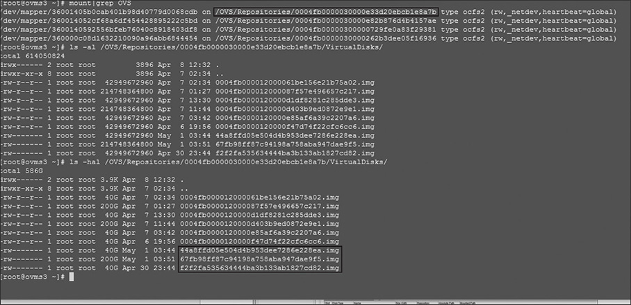
FIGURE 26-4. Putty session showing the virtual disks used by the Oracle VM guest
Next, the virtual disks used by Oracle VM guest can be found in a similar fashion: namely, after expanding the VM guest in the VM Manager GUI, you can use the Disks tab to list the disks used by the guest virtual machine. Figure 26-3 shows the Oracle VM Manager’s virtual machine perspective expanded to show virtual disks used by the virtual machine in this example. Figure 26-4 shows the putty session listing the contents of the virtual disk directory within the OVS repository’s mounted filesystem. This is a brute-force approach to identifying the files necessary to restore and/or recover an Oracle VM guest.
It is also important that you understand the difference between the backup and recovery process of a given guest Oracle virtual machine versus the failover process of an entire Oracle VM site. In the first case, consider a simple configuration of a single guest Oracle virtual machine in an Oracle VM environment with a single Oracle VM Server (OVS). The principal BR concepts include recovery of the VM configuration file and recovery of the repository database information (in particular, the various disks used by the Oracle VM guest).
However, when you’re considering failover of a site, much of the Oracle VM environment configuration must already be in place. For disaster recovery, you can find the site preparation utility and tools at the Oracle Technology Network. At the time of this writing, the ovm-tools file can be found in the VM downloads area of Servers & Storage: http://www.oracle.com/technetwork/server-storage/vm/downloads/ovm-tools-3604795.html. You can download the tools along with supporting documentation. In general, the following setup is required:
![]() The Oracle VM Manager is running at the primary and target sites (meaning a separate pool filesystem).
The Oracle VM Manager is running at the primary and target sites (meaning a separate pool filesystem).
![]() The required repository information is being replicated between the sites.
The required repository information is being replicated between the sites.
![]() The network configuration is established at both sites and ready to go.
The network configuration is established at both sites and ready to go.
If the primary site is running an Oracle database, then the Oracle Data Guard product should be configured and failover (or switchover) should be used to change the operational mode of the database. Otherwise, depending on the nature of the failure at the primary site, the target site will go through the steps outlined in the following list:
![]() The target site assumes ownership of the repository.
The target site assumes ownership of the repository.
![]() Disks used by the guest Oracle VM must be updated or otherwise “brought up to speed” with recently committed transactions at the target site.
Disks used by the guest Oracle VM must be updated or otherwise “brought up to speed” with recently committed transactions at the target site.
![]() The Oracle VM guest at the target site is started.
The Oracle VM guest at the target site is started.
![]() The application on the guest Oracle VM is started.
The application on the guest Oracle VM is started.
![]() If necessary, the enterprise DNS configuration is updated with the target failover site.
If necessary, the enterprise DNS configuration is updated with the target failover site.
A key difference between a failover process and a switchover process is that, in the event of a switchover (that is, the primary site is not taken offline), ownership of the repository must be relinquished by the primary site before ownership can be assumed at the target switchover site.
The Pieces and Parts of Oracle VM Backup and Recovery
When considering an Oracle VM backup and recovery or disaster recovery plan, it is important to remember that there are two categories of data: the data that is part of the backup and restoration process and the data that is local to each site and configured specifically for the given site. The key components to an Oracle VM switchover/failover strategy are the data that must be synchronized and the order in which the components must be started (and also the order in which the components must be shut down if the switchover/failover is a controlled process rather than an unexpected event). Note that switchover and failover are for distinctly different objectives and are detailed in the Oracle Database Administration documentation. Switchover is the process in which a switchback is also an objective. A failover is the process in which a switchback is not an option, even if the old primary site is recovered. A failover results in the separation of the original primary site from the Oracle Data Guard configuration. After a failover, the standby site becomes the new primary, and the old primary is henceforth considered “standalone” (if operational at all). Again, more information is available in the Oracle Database Administration documentation.
Site-Specific Local Data
Each site in an Oracle VM DR model contains data that is not part of the disaster recovery process and is otherwise configured to run at that particular site. Data that remains at each local site and is not part of the Oracle VM backup and recovery set includes the following:
![]() Oracle VM Manager (the VM Manager machine’s operating system and the Oracle VM home).
Oracle VM Manager (the VM Manager machine’s operating system and the Oracle VM home).
![]() Oracle VM servers (operating system and storage that’s local to the OVS and is not used by guest virtual machines that are part of failover operational requirements).
Oracle VM servers (operating system and storage that’s local to the OVS and is not used by guest virtual machines that are part of failover operational requirements).
![]() Oracle Enterprise Manager (OEM High Availability data and operations are separate in the overall BR/DR operations).
Oracle Enterprise Manager (OEM High Availability data and operations are separate in the overall BR/DR operations).
![]() Data related to guest Oracle virtual machines that are not part of failover requirements.
Data related to guest Oracle virtual machines that are not part of failover requirements.
![]() Oracle database software and data files (databases that are part of an Oracle VM BR/DR operational requirement should be configured with Oracle Data Guard).
Oracle database software and data files (databases that are part of an Oracle VM BR/DR operational requirement should be configured with Oracle Data Guard).
![]() Pool filesystems are not copied for DR but are copied/backed up for BR.
Pool filesystems are not copied for DR but are copied/backed up for BR.
Oracle VM BR/DR Data
The data that should be included in the replication model or backup set used to keep each site synchronized includes the following general categories.
![]() Repositories Not all repositories need to be included in the backup or replication set for failover operations; rather, only the repositories that contain Oracle VM configuration files, virtual disks used by guest Oracle VM’s targeted for failover, and their related templates and assemblies, if desired.
Repositories Not all repositories need to be included in the backup or replication set for failover operations; rather, only the repositories that contain Oracle VM configuration files, virtual disks used by guest Oracle VM’s targeted for failover, and their related templates and assemblies, if desired.
![]() Storage This includes NFS, SAN, and local storage used by guest Oracle virtual machines targeted to be part of failover operations, as well as any of the Oracle VM guests’ defined physical disks. These include Oracle VM guest operating system disks and Oracle VM application server disks.
Storage This includes NFS, SAN, and local storage used by guest Oracle virtual machines targeted to be part of failover operations, as well as any of the Oracle VM guests’ defined physical disks. These include Oracle VM guest operating system disks and Oracle VM application server disks.
Site Preparation
As stated earlier, one of the assumptions made in this chapter is that each site has an Oracle VM technology stack running in an operational configuration. However, this does not mean identical configurations are necessary. In fact, each site may have a different number and capacity of Oracle VM servers. It does mean, however, that each site is configured to handle whatever operations and loads are required to sustain the Oracle virtual machines that are part of the switchover/failover BR/DR operations. As such, during the installation and configuration of the Oracle VM manager at the target sites, each site will have its own UUID, pool filesystem, and Oracle VM manager database. In addition, each site maintains its own backup and recovery operation of the local site Oracle VM Manager. Each site will also have its own local storage and repositories. The primary site’s Oracle VM Manager backup and unique ID are only mentioned here with respect to general BR/DR best practices for Oracle VM.
The important configuration items for target sites include the following:
![]() Network configuration
Network configuration
![]() File server and SAN server virtual disk and physical disk capacity
File server and SAN server virtual disk and physical disk capacity
![]() Repository storage capacity
Repository storage capacity
![]() CPU and memory
CPU and memory
An important aspect of network configuration is how the enterprise domain name services (DNS) will be handled before, during, and after switchover/failover operations. In their simplest form, the network configuration changes required in support of switchover/failover operations are assumed here to be limited to the virtual machine network required to support only the communications between Oracle virtual machines within a given site. The complexities introduced in support of external communications (that is, communications from the outside world to virtual machines, and vice versa) are voluminous. Again, in their simplest form, these networking operations would include network address translation (NAT) and/or local DNS modification to allow routing to machines within the virtual machine network after virtual machines have been transitioned from one site to another.
In the Middle—Establish Backup and Recovery Processes
After you have identified the data related to the restore and recovery of the Oracle VM environment, you need to implement the method by which the data is backed up, restored, and/or synchronized (that is, replicated). Having an environment equipped with an Oracle ZFS appliance is the recommended best practice. If, however, a different storage strategy is employed, the mechanism used for storage synchronization/replication will vary from vendor to vendor. In the event a replication mechanism is not available, manual synchronization will be required. This means that during switchover/failover operations, you must pause the automated process at the step when the storage must be synchronized between the primary and target sites. Although this is fully supported, it is highly recommended that you put an automated replication mechanism in place, if at all possible, to allow full automation of the switchover/failover operation, from start to finish.
The controlled process to switch over from the primary site to the target site begins with shutting down the application processes and Oracle virtual machines of the primary site. The organized shutdown is followed by the primary site’s server pool relinquishing ownership of the repositories that are part of the switchover/failover event. At this point, the requisite data from the primary site must be already replicated to the target site(s). Replication is an ongoing task; a final small synchronization is part of the switchover, which means the replication is ongoing and scheduled (or continuous or scheduled; the latter may be the preference to help avoid immediate propagation of corrupted data). Keep in mind that continuous replication on ZFS is not synchronous replication.
Replicated data should include the following:
![]() Repository data (guest Oracle VM configuration files and repository-based virtual disks)
Repository data (guest Oracle VM configuration files and repository-based virtual disks)
![]() Shared storage data (physical disks that are defined by LUNs on SAN storage, and/or files on file server storage)
Shared storage data (physical disks that are defined by LUNs on SAN storage, and/or files on file server storage)
![]() Local storage data (physical disks that are defined by LUNs and/or disks local to the OVS machines and provisioned to guest Oracle VMs that are defined to run on the OVS and are part of the switchover/failover site operations)
Local storage data (physical disks that are defined by LUNs and/or disks local to the OVS machines and provisioned to guest Oracle VMs that are defined to run on the OVS and are part of the switchover/failover site operations)
After the data has been synchronized to the target site, the switchover/failover operations resume with the target site taking ownership of the repository data. Once the target site owns the repositories, the guest Oracle virtual machines are started in the proper sequence. Again, this is why it is so important for you to understand and document the process! As each guest Oracle virtual machine is started at the target site, the correlated processes may be started, provided the associated processes have also been started, as necessary. For example, if an application server requires an Oracle database, that database must be started prior to the application server processes initiating. It is therefore critical that the application server not be started before the database server (and the associated database) is started. In the case of an Oracle database, Oracle Data Guard is the database availability mechanism that’s used, in which case the database server would have already been operational and an Oracle database Data Guard switchover or failover process would have already been completed (Oracle Site Guard automates all the aforementioned tasks, including the Data Guard steps).
In the End—Testing Recovery and Switchover Processes
The final stage of the Oracle VM switchover/failover process involves the configuration changes required to establish the former primary site as a target site; then the new target site (used for the switchover/failover operation) needs to be established as the new primary site. This usually involves establishing storage replication changes and/or other adjustments to the former primary site. These adjustments include hardware and/or software upgrades, patching, and other operations. When the time is right, another switchover operation can take place, and the primary site can once again earn its place as the enterprise primary site for the given operational applications and databases. Ultimately, the only difference between the before and after perspectives (with respect to switchover/failover operations) is the direction of storage replication. The real benefit to using Oracle Site Guard is realized during unintentional site failover rather than the controlled failover of just the Oracle virtual machines. And, for large complex sites, the value of Site Guard is the ability to trigger switchovers with the push of a single button for routine maintenance or temporarily rebalancing application workloads to other sites, not just “disaster recovery.”
Preparing the OEM Environment
And now we get to the crux of the biscuit: the primary tool of the Oracle Site Guard solution is Oracle Enterprise Manager. As mentioned earlier, it is assumed the primary and target sites are configured and ready for site switchover and/or failover operations. If this is the case with the use of Oracle Enterprise Manager, then the following are assumed to be in place:
![]() The OEM 12c or 13c base product has been deployed as described in Part V of this book using a Level 3 or Level 4 MAA deployment. (Basically, OEM is needed at both sites or a third site; if OEM is only available at one site and that site goes down, the DR mechanism/engine is lost.)
The OEM 12c or 13c base product has been deployed as described in Part V of this book using a Level 3 or Level 4 MAA deployment. (Basically, OEM is needed at both sites or a third site; if OEM is only available at one site and that site goes down, the DR mechanism/engine is lost.)
![]() The primary and target sites’ Oracle VM Managers have been discovered and configured as part of the cloud infrastructure, as described in Part V of this book.
The primary and target sites’ Oracle VM Managers have been discovered and configured as part of the cloud infrastructure, as described in Part V of this book.
![]() All the Oracle VM servers have been discovered and configured as part of the cloud infrastructure, as described in Part V of this book.
All the Oracle VM servers have been discovered and configured as part of the cloud infrastructure, as described in Part V of this book.
![]() All the guest Oracle virtual machines that are part of the sites participating in switchover/failover operations have been discovered and the OEM management agents have been deployed.
All the guest Oracle virtual machines that are part of the sites participating in switchover/failover operations have been discovered and the OEM management agents have been deployed.
These requisite configuration items are needed in order to proceed with configuring Oracle Site Guard in OEM. Figure 26-5 shows the Oracle VM Manager (in this example, named ovmmgr) that has been discovered and added into the cloud virtualization infrastructure of OEM 13c, ready for use in the creation of an Oracle Site Guard primary site.

FIGURE 26-5. Oracle VM Manager primary site in OEM 13c
Although the process for installing and configuring a complete OEM environment is well explained within the OEM 13c (13.2) documentation, it is briefly summarized here to correlate the manual steps previously listed with the automated failover described in the next section. Basically, the steps to configure OEM in support of Site Guard are as follows:
1. Create the cloud infrastructure.
2. Discover the targets and create administrators and credentials.
3. Create and refine the systems (both the primary and target).
4. Create and configure the software libraries (used for storage and management of additional custom scripts or software).
5. Refine the definition of the discovered sites.
The actual implementation of these steps can take several weeks to complete. However, the benefit is astounding! For example, traditionally, a controlled switchover of a Data Guard–configured database can take as little as 45 seconds, whereas the manual switchover or failover of an application and database within an Oracle VM–based data center can take many hours. Using OEM in the same manual failover with a properly defined set of primary and target sites can be accomplished in just a few minutes. Imagine what company management would say about the impact to the bottom line with an RTO and RPO of just a few minutes!
Automating Switchover/Failover
The processes and configurations needed in support osf establishing an OEM-based controlled switchover are established by following these steps:
1. Define the cloud infrastructure.
2. Discover and configure Oracle VM Manager and Oracle VM Server within the cloud infrastructure.
3. Discover the Oracle virtual machine target (optional).
4. Create and define generic systems (sites).
5. Create and customize operation plans, which include the addition of scripts used for disaster recovery operations if you’re using EMC, HDS, or something other than NetApp or ZFS.
6. Schedule operational plans and health checks and execute Oracle Site Guard operations.
7. Update site roles and define new operational plans for subsequent switchover/failover operations.
The workflow associated with an automated switchover/failover may take several weeks to complete. But again, the benefit is realized the first time the operation is required. These processes are detailed in the Oracle Enterprise Manager 13.2 documentation and demonstrated in the following Oracle-sanctioned videos and white papers.
Key white papers include the following:
![]() SN21001-6.1: “Oracle VM 3: Getting Started with Disaster Recovery”
SN21001-6.1: “Oracle VM 3: Getting Started with Disaster Recovery”
![]() SN21305-1.0: “Oracle VM 3: Implementing Oracle VM Centric DR Using Site Guard”
SN21305-1.0: “Oracle VM 3: Implementing Oracle VM Centric DR Using Site Guard”
![]() SN21705-0.4: “Oracle VM 3: Required Software for Oracle VM–Centric DR Using Site Guard”
SN21705-0.4: “Oracle VM 3: Required Software for Oracle VM–Centric DR Using Site Guard”
![]() SN21810-0.1: “Oracle VM 3: Planning Network for Oracle VM–Centric DR Using Site Guard”
SN21810-0.1: “Oracle VM 3: Planning Network for Oracle VM–Centric DR Using Site Guard”
![]() SN21811-0.4: “Oracle VM 3: Planning Storage for Oracle VM–Centric DR Using Site Guard
SN21811-0.4: “Oracle VM 3: Planning Storage for Oracle VM–Centric DR Using Site Guard
![]() SN21812-0.1: “Oracle VM 3: Planning the Site Guard Deployment for Oracle VM–Centric DR”
SN21812-0.1: “Oracle VM 3: Planning the Site Guard Deployment for Oracle VM–Centric DR”
![]() SN21901-2.1: “Oracle VM 3: Implementing Networks for Disaster Recovery”
SN21901-2.1: “Oracle VM 3: Implementing Networks for Disaster Recovery”
![]() SN21301-1.4: “Oracle VM 3: Oracle VM–Centric DR Validating Failover Process”
SN21301-1.4: “Oracle VM 3: Oracle VM–Centric DR Validating Failover Process”
Also, the material covered in this chapter is documented in eye-watering detail in the following Oracle documentation and white papers:
![]() Oracle Enterprise Manager Cloud Control Online Documentation Library, Release 13.2 / Management: Site Guard Administrator’s Guide
Oracle Enterprise Manager Cloud Control Online Documentation Library, Release 13.2 / Management: Site Guard Administrator’s Guide
![]() Oracle VM Release 3.4 documentation
Oracle VM Release 3.4 documentation
![]() Repository Backup: Oracle VM Manager User’s Guide for Release 3.4
Repository Backup: Oracle VM Manager User’s Guide for Release 3.4
![]() VM Manager Backup and Recovery: Oracle VM Administration Guide for Release 3.4
VM Manager Backup and Recovery: Oracle VM Administration Guide for Release 3.4
![]() Oracle VM 3 Backup and Recovery Best Practices Guide (white paper)
Oracle VM 3 Backup and Recovery Best Practices Guide (white paper)
![]() Oracle VM 3: Getting Started with Disaster Recovery Using Oracle Site Guard (Doc ID 1959182.1)
Oracle VM 3: Getting Started with Disaster Recovery Using Oracle Site Guard (Doc ID 1959182.1)
Finally, here are some helpful Oracle Site Guard videos:
![]() https://youtu.be/3mWuu-XRjDU
https://youtu.be/3mWuu-XRjDU
![]() https://www.youtube.com/watch?v=vz1GGxeqdOM
https://www.youtube.com/watch?v=vz1GGxeqdOM
![]() https://www.youtube.com/watch?v=vz1GGxeqdOM&t=189s"&
https://www.youtube.com/watch?v=vz1GGxeqdOM&t=189s"&
![]() https://www.youtube.com/watch?v=vz1GGxeqdOM&t=189s"t=189s
https://www.youtube.com/watch?v=vz1GGxeqdOM&t=189s"t=189s
Summary
Backup, restore, and recovery are not just “nice to have” practices. Like it or not, they are practices that are certain to be eventualities. Regardless of the tactical or strategic plans, it is inevitable that the manual steps, actual components, and the lifecycle of the processes become part of the overall enterprise solutions. In addition, the use of automation will speed up the processes and reduce or eliminate the errors inherent in manual steps. Although the two approaches (manual and automated) are not mutually exclusive (manual processes may be interjected during an automated Site Guard operation), the critical nature of disaster recovery merits having both well documented and understood by those who will be held responsible and accountable for the success of the operation.