In this chapter, we will explore the 3D Modeling and printing of the NatBot. Just like the previous chapter, I will explain all new features used to create the 3D models. The first thing we will talk about is the requirements for the 3D chassis of the NatBot. Then we will look at the new functions used to create all the 3D models for the NatBot. Next, we will talk about each individual model and what measurements are important in order to make each of these mounts, brackets, and so on. After that, we will take a look at setting up the 3D printer to print each of these models using the Simplify3D slicer. Finally, we will look at the assembly of the NatBot which will include a short list of hardware needed in order to put together the NatBot. If you do have any issues with the model, don’t worry; the full model is supplied with this book. If you need to reference it, that is perfectly fine. So, now that the introduction is completed, let us take a look at the requirements for the NatBot.
Final Project: NatBot
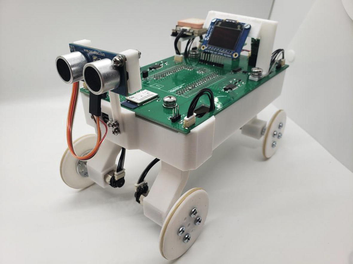
A fully assembled NatBot
Requirements Gathering (3D Model)
Mounts for the motors should be independent of the chassis for easy printing and to make the NatBot more modular.
The PCB should sit on top of the NatBot chassis for easy access.
The GPS needs a mount hovering over the NatBot PCB.
The LCD needs a mount hovering over the NatBot PCB.
The Ultrasonic Sensor needs to be placed in the front of the NatBot chassis.
The NatBot needs to have a rover-like appearance.
The battery needs to be secure and located close to power input.
The NatBot needs to have a panel mount micro USB port for ease of programming the robot.
The NatBot should not be more than 200 x 150 x 175mm.
Wheels should be modular and generic and do not exceed 60mm in diameter.
Okay! So, we have our requirements; we should be able to think through them and start to design the NatBot. In the next section, we will discuss each requirement and come up with a solution for each.
Outlining the 3D Model Requirements
Mounts for the motors should be independent of the chassis for easy printing and to make the NatBot more modular.
This pretty much means we need to have the motor mounts separate from the main chassis to make them easy to print, and also if the customer (Naticom) wants to add or update the mounts later, they can. The motors need to be independent and should resemble a rover-style set of motor mounts.
The PCB should sit on top of the NatBot chassis for easy access.
Another easy requirement, just make the PCB the “Lid” of the chassis; we will need to make sure that we have at least four of the five mounting holes on the PCB and have mounting posts, so the board is secured. We might even use brass inserts for more rigidity.
The GPS needs a mount hovering over the NatBot PCB.
The LCD needs a mount hovering over the NatBot PCB.
The Ultrasonic Sensor needs to be placed in the front of the NatBot chassis.
We will need to create mounts for the GPS, LCD, and Ultrasonic Sensor; these can be fastened with hardware so the mounts should be able to handle vibration. We will also need to make sure each of these components is away from other hardware on the NatBot PCB. The Ultrasonic Sensor needs to be placed at the front of the NatBot which will also help with the rover appearance requirement.
The NatBot needs to have a rover-like appearance.
As stated earlier, all features will give the appearance of a rover-style robot.
The battery needs to be secure and located close to power input.
The battery will need to be in an easy access area and secured to the chassis; it should also be close to its input as the battery cable is not very long.
The NatBot needs to have a panel mount micro USB port for ease of programming the robot.
The NatBot will have a panel mount micro USB port at the front of the robot to make it easier to program; without this panel mount, the user would have to remove the NatBot PCB every time they wanted to program it.
The NatBot should not be more than 200 x 150 x 175mm.
The NatBot cannot be more than 200mm long, 150mm wide, and 175mm tall. This will be a small rover, but it will still be a challenge to meet this requirement with such a large PCB.
Wheels should be modular and generic and do not exceed 60mm in diameter.
They do not give us too much information on this, so we will just develop a simple 50mm wheel that will directly connect to the metal hubs we used for the previous project.
Fusion 360 Functions Explained
- 1.
First, open Fusion 360 if it is not already opened.
- 2.
Create a new component and name it “Cube.” See Figure 8-2.
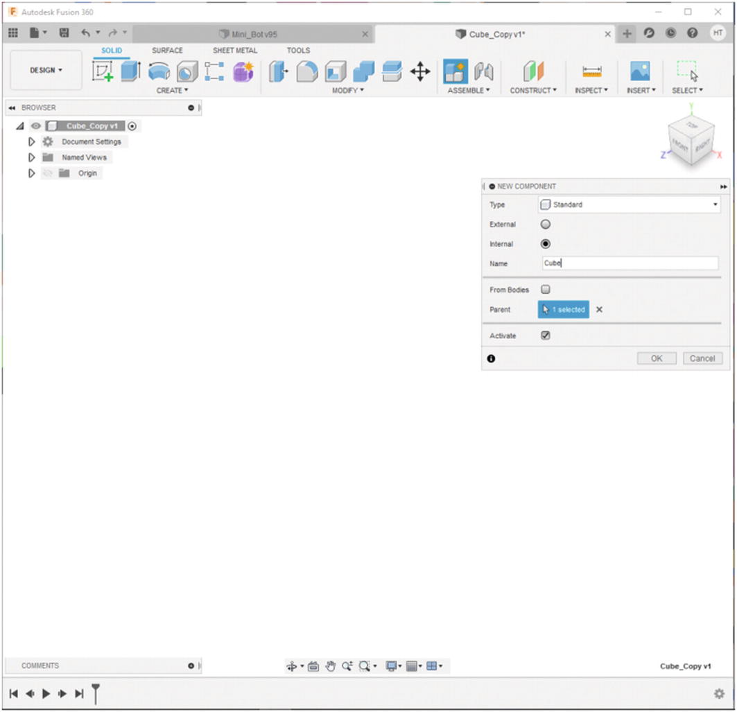
Create a new component named “Cube”
- 3.
Create a 5mm by 5mm by 5mm cube. See Figure 8-3.

5 x 5 x 5mm cube
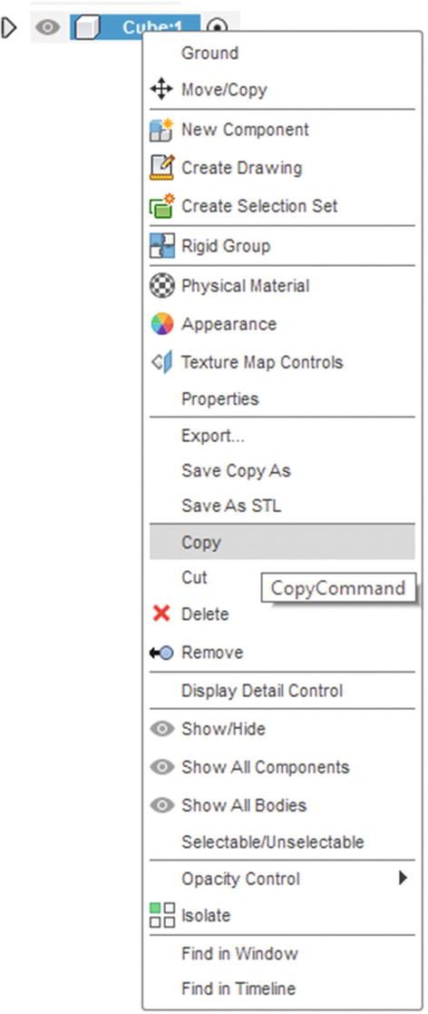
Select “Copy”
- 4.
Right-click the cube component and select “Copy.”
- 5.
Then right-click the Cube_Copy assembly and select “Paste New.” This will create a new body that is separate from the original cube. This is important if you want to modify just one of the components. This was used with the wheelbases of the rover. See Figure 8-5.

Select “Paste New”
- 6.
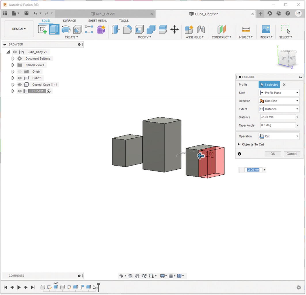
Notice that if you select the copied cube and change it, the original does not change with it. See Figure 8-6.
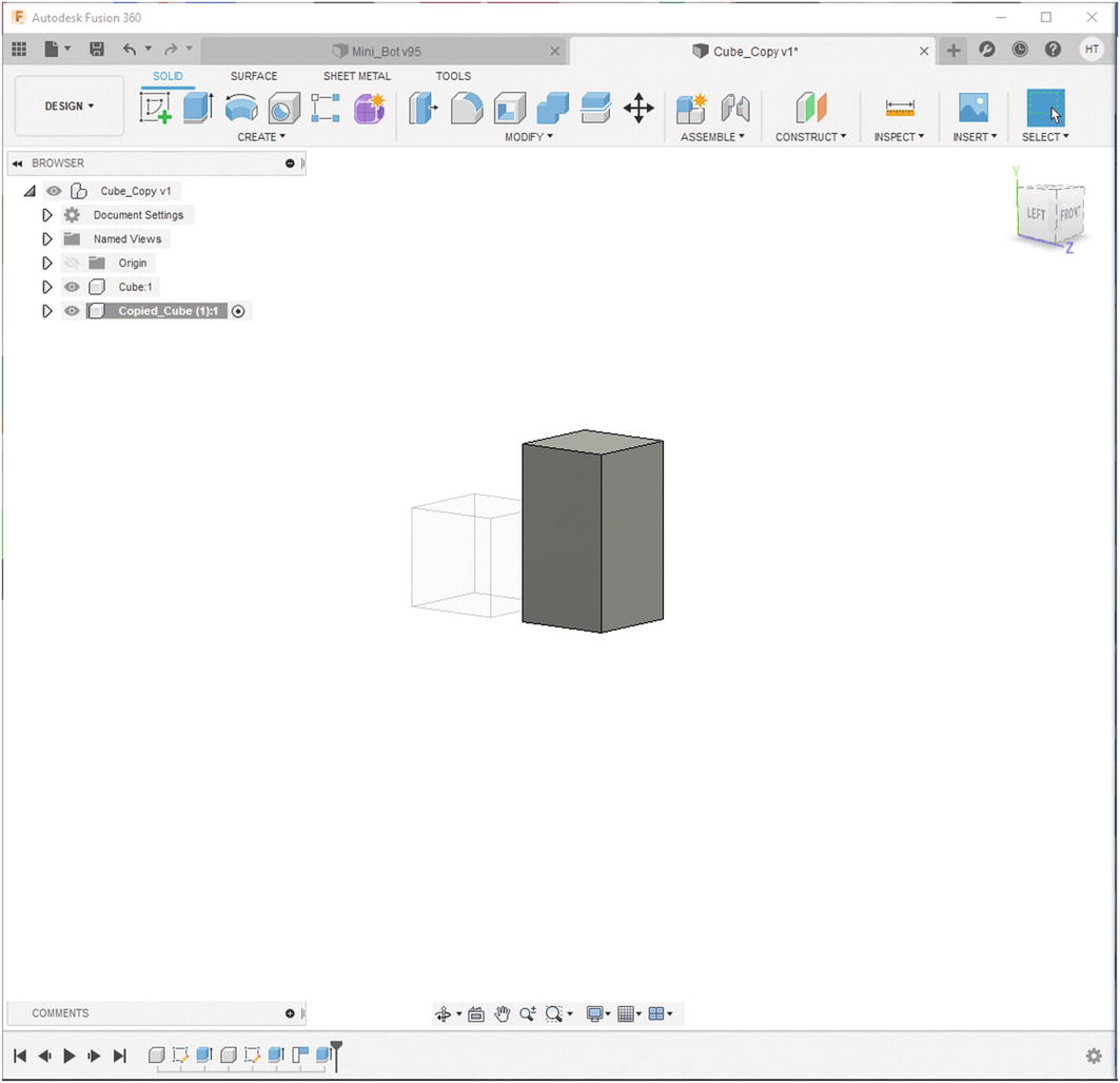
The pasted component is a completely separate component
- 7.
If you do want all of the components to match, then all you need to do is select “Paste” instead of Paste New.” See Figure 8-7.
If you just paste a component, both components will share dimensions
- 1.
Using the same example from the previous section, select one of the faces on a cube. See Figure 8-8.
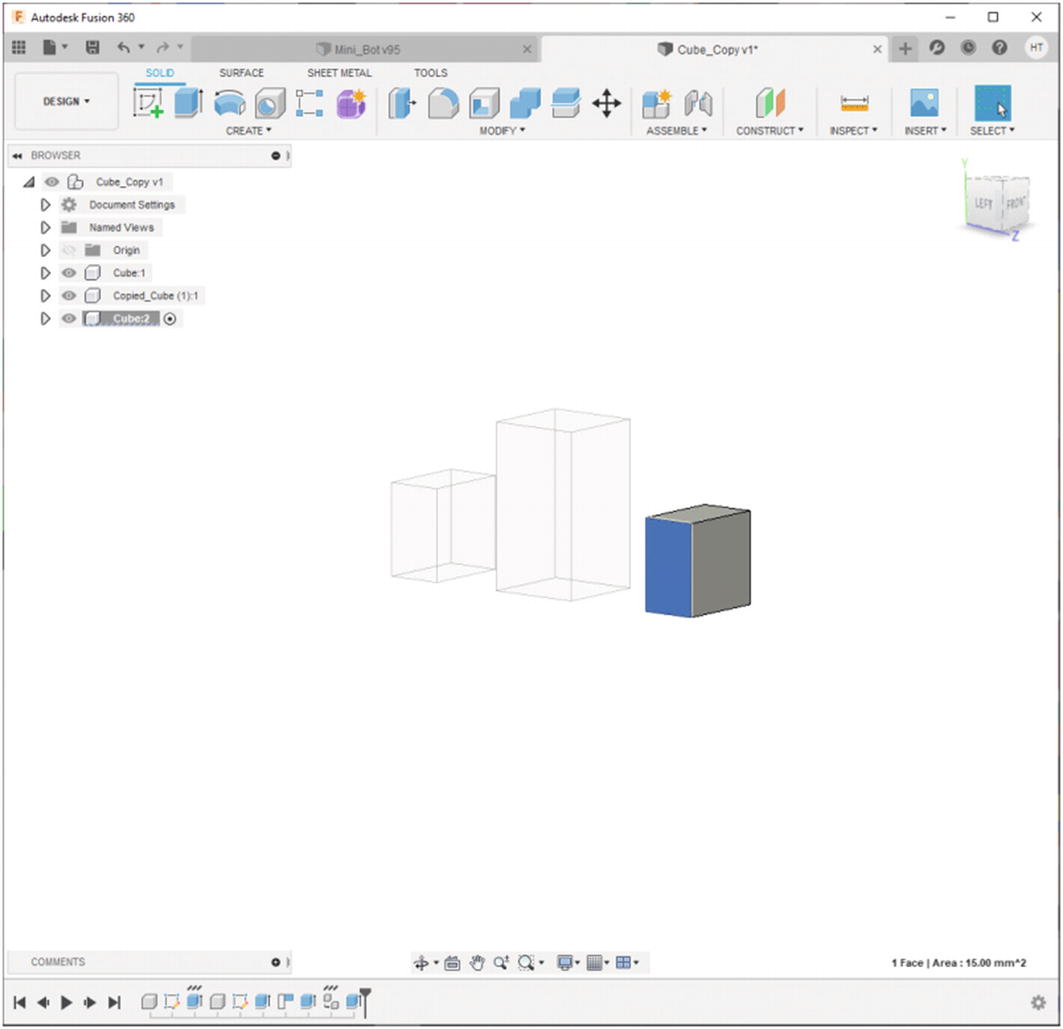
Select a face on a cube
- 2.
Select Construct ➤ Offset Plane. See Figure 8-9.
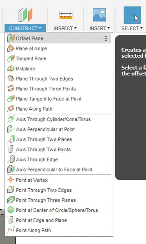
Select the “Offset Plane”
- 3.
Now move the offset plane to 10mm. See Figure 8-10.

Make the offset plane 10mm from the cube
- 4.
Now with this plane, you can create a sketch; you can even project faces onto the offset plane that can be used to make other bodies.
- 1.
Create a new model in Fusion 360.
- 2.
Create a cylinder with a diameter of 50mm and a height of 10mm. See Figure 8-11.

Create a new component and make a cylinder
- 3.
Create a new sketch and make a 10mm circle around the center point of the top of the cylinder. See Figure 8-12.

Create a 10mm circle on the cylinder
- 4.
Make this circle a construction line by selecting it and pressing the “x” key.
- 5.
Draw a 3mm circle on the perimeter of the 10mm circle. See Figure 8-13.

Create a 3mm circle on the perimeter of the 10mm circle
- 6.
Select the Circular Pattern from the CREATE menu at the top. See Figure 8-14.
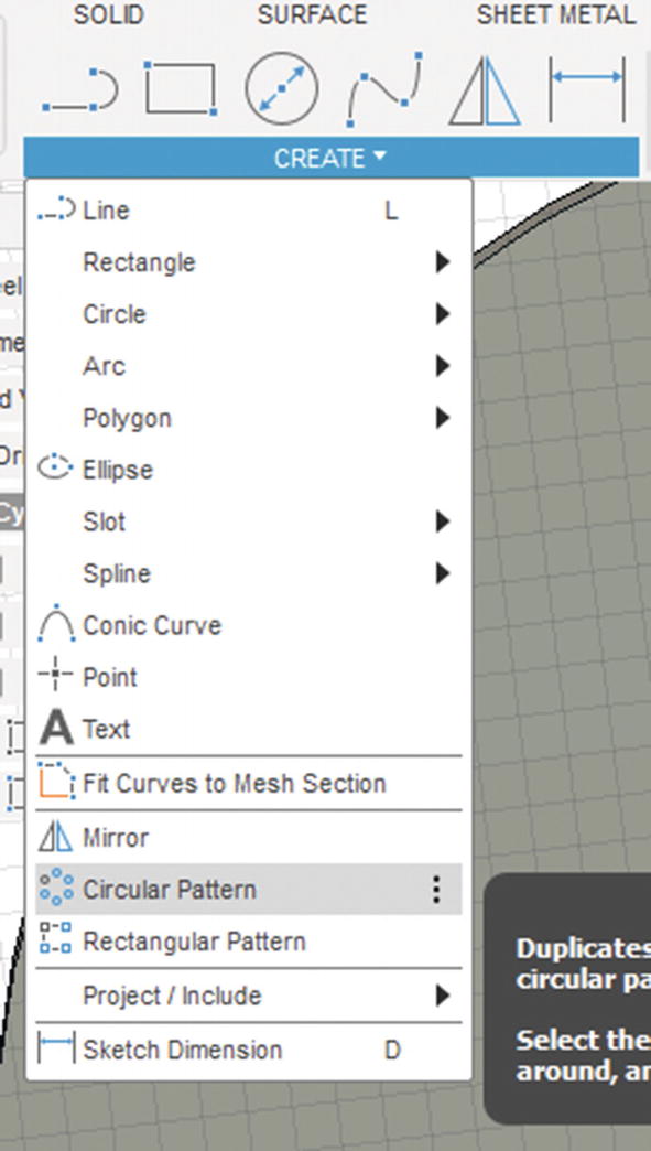
Select “Circular Pattern”
- 7.
Select the 3mm circle as the “Object,” and the “Center Point” will be the center of the 10mm circle. You will notice once you select these, you will have three circles on the screen; you can add more just by increasing the quantity. See Figures 8-15 and 8-16. Click “OK” when you are done, and you will see that these circles have been populated.
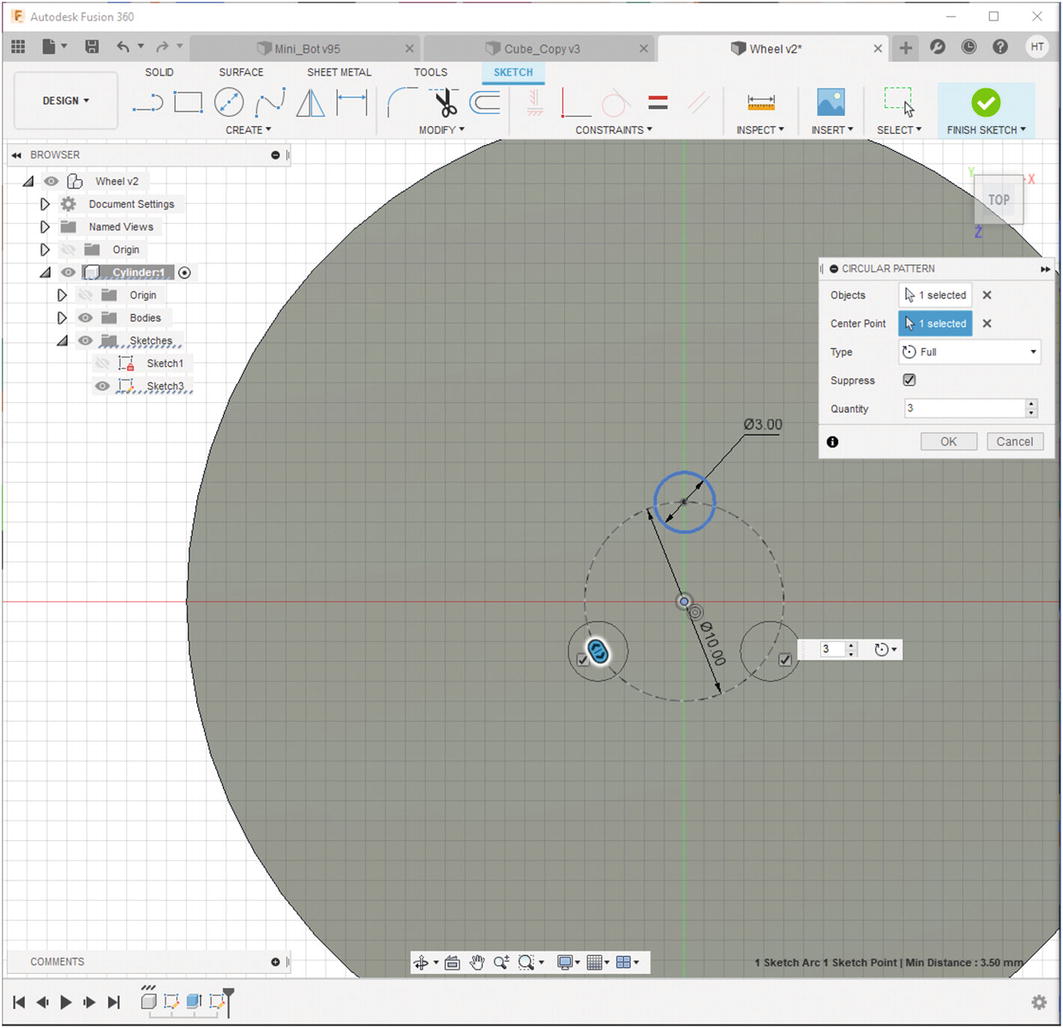
Notice three circles populate on the cylinder

For the quantity, put “6”
- 8.
Click Finish Sketch.
- 9.
Select the six circles and press the “E” key. Extrude these holes to the bottom side of the cylinder. See Figure 8-17.
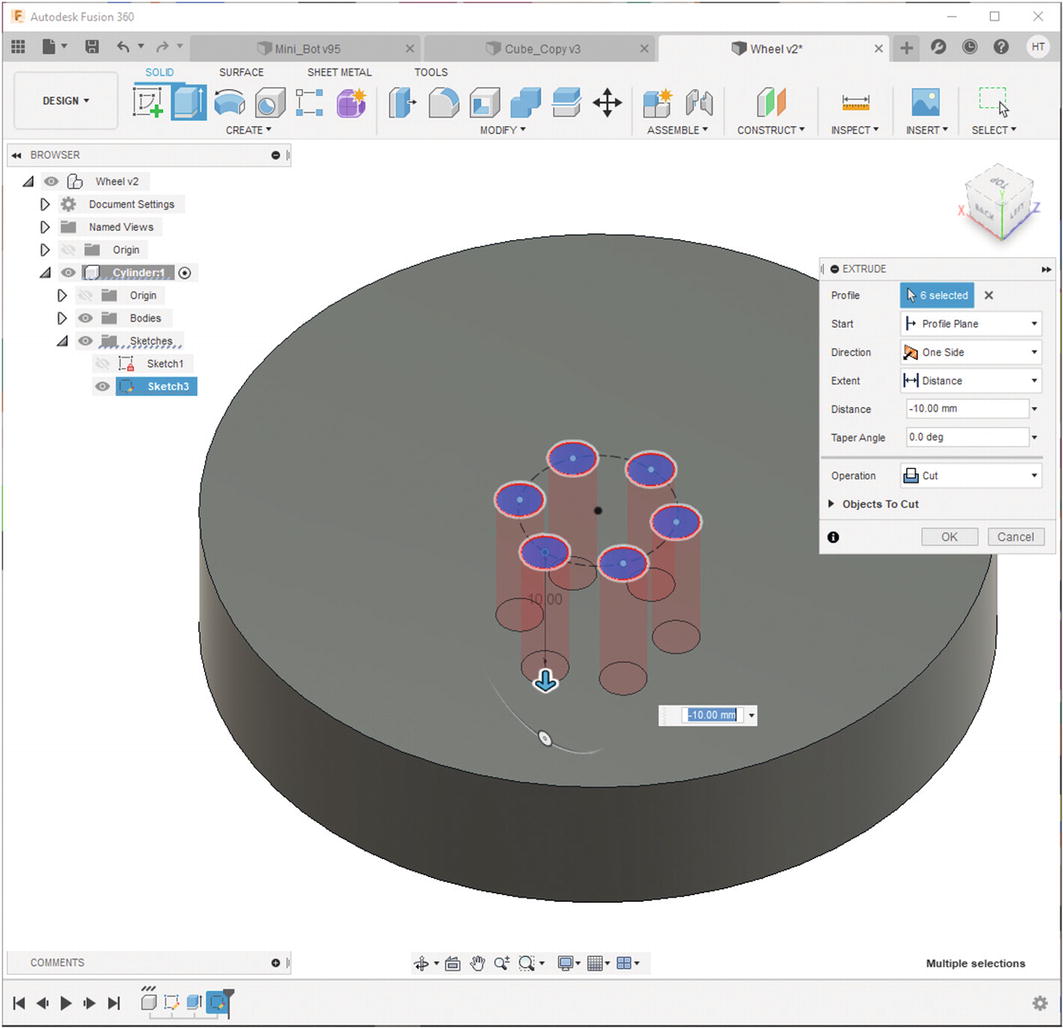
Extrude to make six holes
Alright! That puts us in a good spot to start to talk about the various models you will be creating in this chapter. The next section will discuss each of these models.
Features of the NatBot 3D Model Explained
In this section, we will go through each 3D model that is needed to create the NatBot. Each part is explained, and each important dimension is discussed to make it easier to create the 3D model. Remember, you have some creative license here; you can make the NatBot exactly as this book does, or you can make the NatBot your own. It is entirely up to you. Let us get started.
NatBot Chassis
So the NatBot needs to have a few features that will hold the PCB and the battery in place. The motor assemblies and the GPS, LCD, and Ultrasonic mounts need to attach to it. Finally, there needs to be a place for a micro USB panel mount. The nice thing is the GPS, LCD, Ultrasonic Sensor, and the motor assembly mounts are all going to be designed by us, so we can make them any style we want. The same goes for the PCB, but we have already designed it a certain way, so we need to make sure we capture the PCB properly. The micro USB panel mount will need to have a spot made for it as we had to source that component.
Let us look at each section of the chassis.
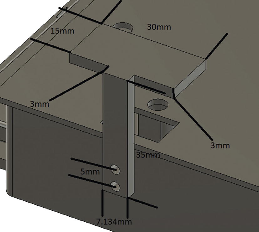
Battery Holder

Dimension of the battery holder on the NatBot chassis
Hole mount for wheelbase assemblies
The key measurements are the batteries’ length, width, and height.
Motor Assembly Mounts
The motor assemblies are our creation. Naticom has suggested they do want to keep it modular for future upgrades, and the PCB does include four servo motor channels, so we might want to make the mounts the same as a small servo, so if they want to use those mounts with servos, they can. See Figure 8-19.
The key dimensions are the small Servo that could be used later for the NatBot. This includes the length, width, and height of the servo motor.
Ultrasonic Sensor Mount
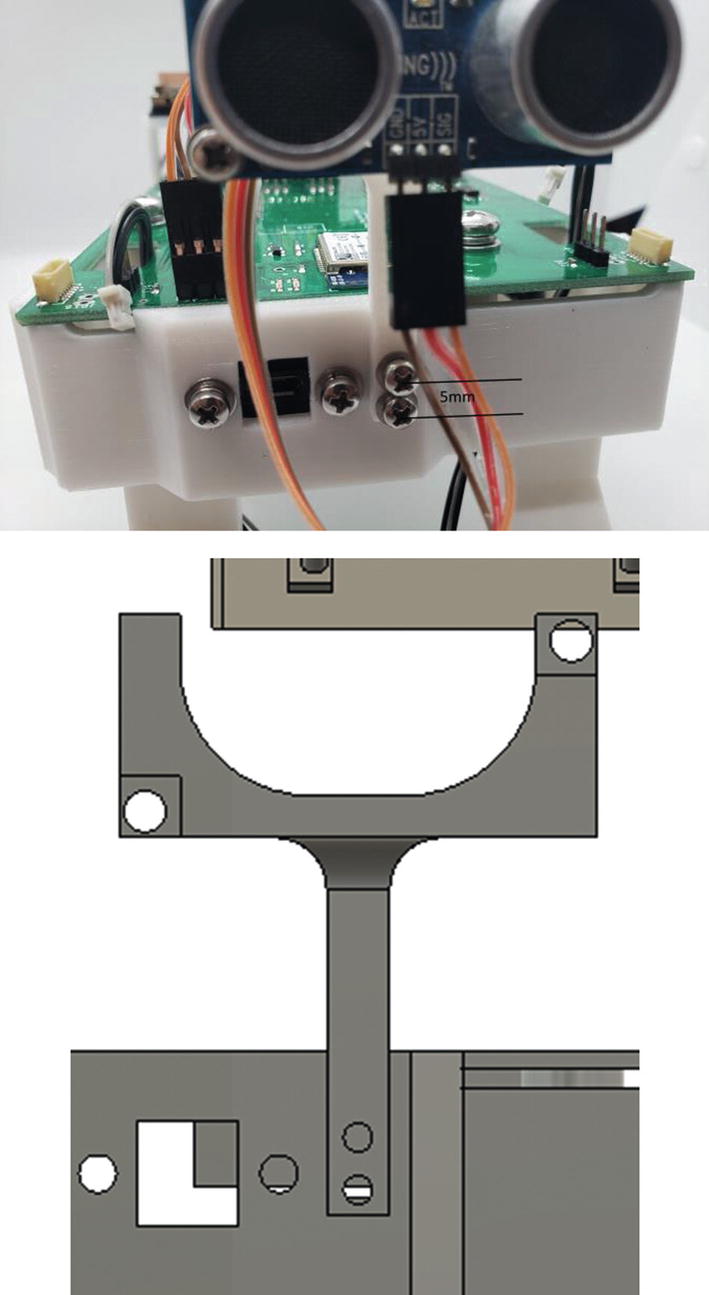
Ultrasonic Sensor Mount chassis mount
The key dimensions are the size of the screw.
LCD Mount
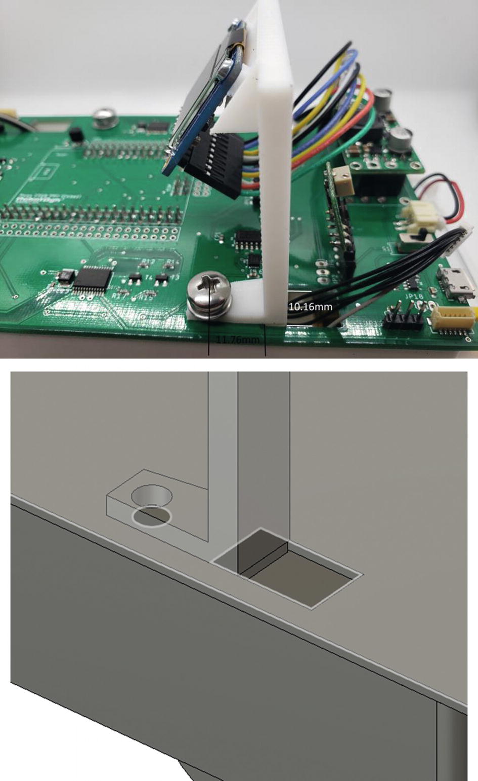
LCD PCB mount
The key dimensions are the M5 screw and the distance from the M5 hole to the motor cable passthrough.
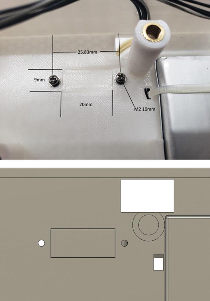
Micro USB Panel Mount

Micro USB panel mount
The key dimensions are the length between the two mounting holes and the height and width of the access hole.
PCB Mounting

Make sure to use a DXF export in order to get the exact dimensions of the NatBot PCB
The key dimensions are the hole locations on the PCB, the motor passthrough locations, the length, height (with and without the Arduino attached), and width of the PCB. Using the DXF function to capture the PCB is a good practice as it will give you all of these dimensions minus the height of the PCB.
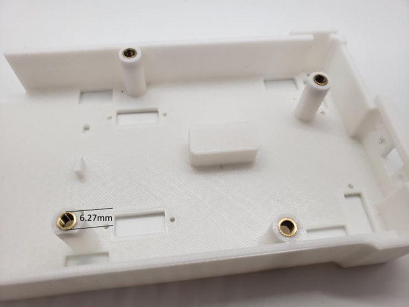
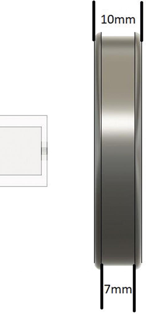
Hole diameter of brass inserts

Arduino post
Finally, remember that the NatBot can only be so tall; the current height of the PCB is 28.22mm with a plastic thickness of 3mm, which should make the NatBot strong enough to withstand some impact.
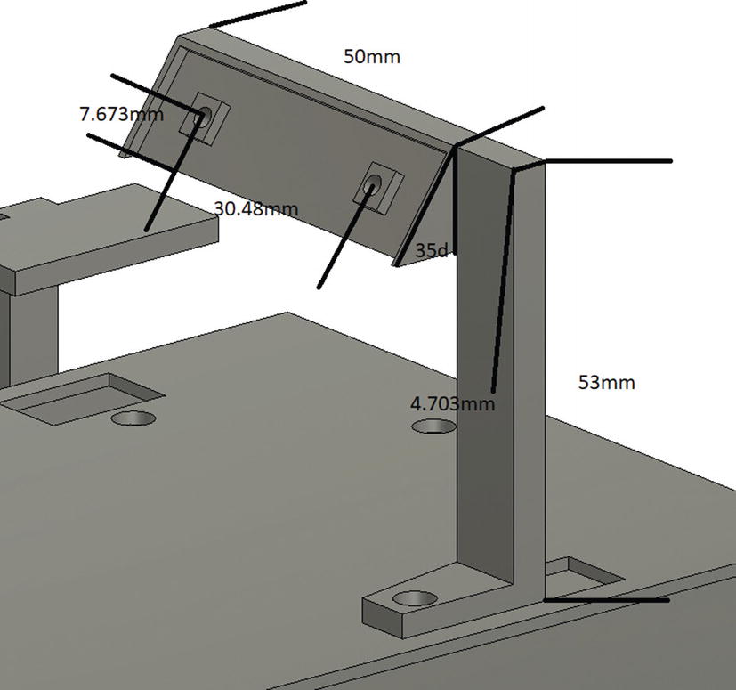
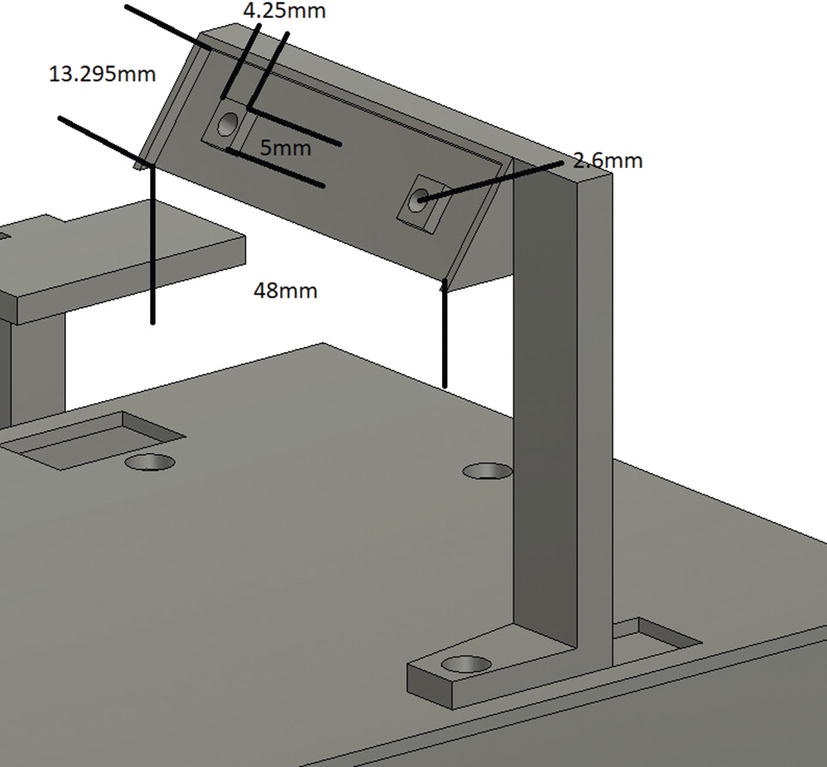
NatBot Ultrasonic Sensor Mount
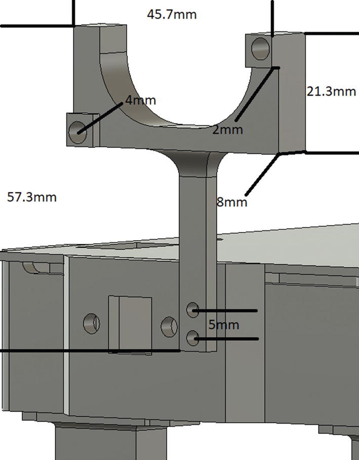
Ultrasonic Sensor Mount dimensions

Ultrasonic Sensor Mount dimensions (Cont.)
This mount needs to attach to the front of the NatBot.
NatBot LCD Mount
LCD mount dimensions
LCD mount dimensions (Cont.)
NatBot GPS Mount
GPS mount dimensions
NatBot Front and Rear Wheelbase

Front wheelbase dimensions

Front wheelbase dimensions (Cont.)

Rear wheelbase dimensions

Wheelbase motor depth
The total height of the NatBot cannot exceed 175mm, so make sure you do not make these wheelbases too tall.
NatBot Wheels
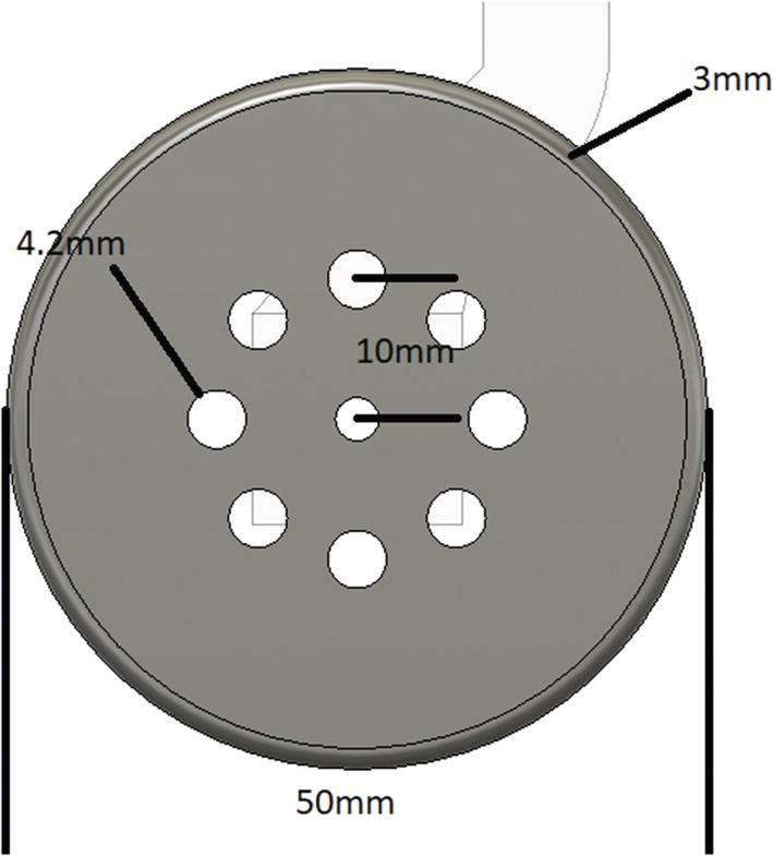
Wheel dimensions
Wheel dimensions (Cont.)
3D Printing the NatBot
Well , now it is time to test these dimensions and try to print the NatBot. In this section, I will explain what to print together, how to print, what infill % to use, and where to put support structures. Let us get started with printing the chassis:
Printing the chassis:
Infill % should be 25 to 30%.
Use PLA at 190 to 220C.
Estimated time to print: 4hrs.
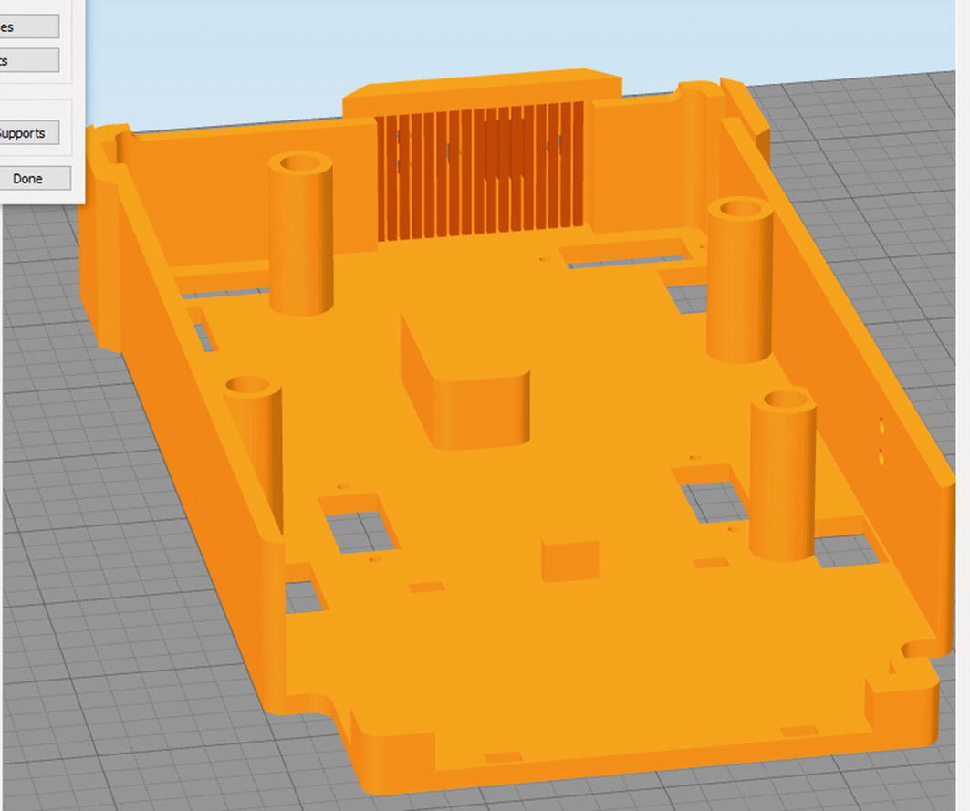
Printing the NatBot chassis
Printing the wheels and wheelbases:
Infill 25 to 35%.
Use PLA at 190 to 220C.
Estimated time to print: 7hrs.
Auto generate support material; use 2mm for the “Support Pillar Resolution” and 35 degrees as the “Max Overhang Angle.”
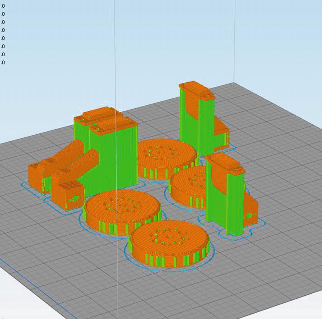
Printing the wheels and wheelbases
Printing the LCD, GPS, and Ultrasonic Sensor Mounts:
Infill % should be 25 to 30%.
Use PLA at 190 to 220C.
Estimated time to print: 1hr.
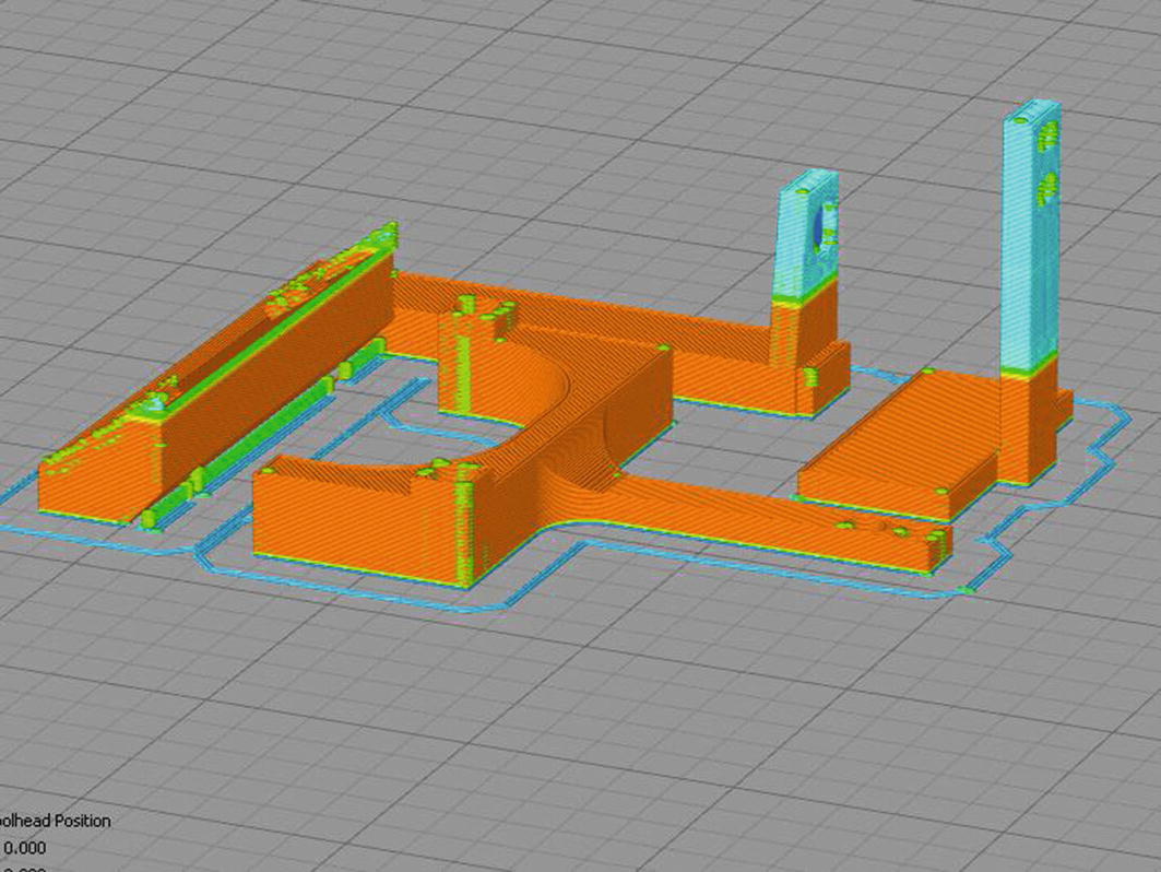
Printing the mounts
That should be all of the printable components. The next section will discuss assembling the robot.
Fit Check and Assembly
4 x M5 10mm pan head screws (for PCB mounting)
4 x M5-0.8 OAL 5.83mm brass inserts (for PCB mounting)
12 x M2 10mm pan head screws (for wheelbase, Ultrasonic, GPS)
14 x M2 nuts
2 x M2 12mm pan head screws (for LCD mounting)
2 x M3 10mm pan head screws (for micro USB panel mount)
8 x M1.6 4mm (can be cut down from a longer M1.6 screw)
4 x 30mm gasket or rubber bands (for wheels)
1 x Adafruit micro USB panel mount cable (pn: )
4 x micro motor couplers (pn: Servo City 545348)
4 x micro geared motors (pn: Pololu 2209)
2 x 145 by 2.5mm zip ties
4 x JST SH Jumper Wire (pn: SparkFun GPS-09123)
1 x GPS module (pn: )
1 x Ultrasonic Sensor (pn: )
1 x Adafruit OLED LCD (pn: )
1 x 2Ahr Lithium Ion (pn: SparkFun PRT-13855)
2 x 10 position dupont housing
26 x female dupont crimps
2 x 3 position dupont housing
Small piece of Velcro
24 AWG wire
- 1.
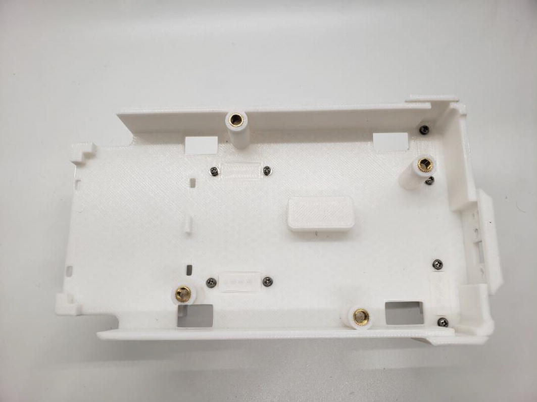
Press four of the brass inserts into the NatBot chassis using a small hammer or a vise to evenly push them into the PCB mounting posts. See Figure 8-40.
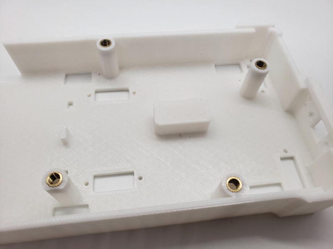
Press the brass inserts into the chassis
- 2.
Insert the micro motors into the wheelbases; they should fit snuggly. If they do not fit, try and use a file or X-Acto knifetm to clean the area around the motor housing on the wheelbase. If you have the rotary encoders for the motors, make sure they are already attached. See Figure 8-41.

Insert each of the geared motors into the wheelbases
- 3.
Using eight of the M1.6 4mm screws, attach the wheelbase to the micro motors. See Figure 8-42.

Use the M1.6 4mm screws to attach the motor to the wheelbase
- 4.
Attach the wheelbase prints to the NatBot chassis. They should be a bit of a tight fit, but if you are having trouble fitting them in, you can sand down the top a little to help them fit better. See Figure 8-43.

Attach the wheelbases to the NatBot chassis
- 5.
Use eight of the M2 10mm bolts and eight of the M2 screws to secure the wheelbases to the chassis. See Figure 8-44.
Secure the wheelbases to the chassis using 8 x M2 10mm screws and nuts
- 6.
Attach the Ultrasonic Sensor to the Ultrasonic Sensor Mount using two of the M2 10mm screws and two M2 nuts. See Figure 8-45.
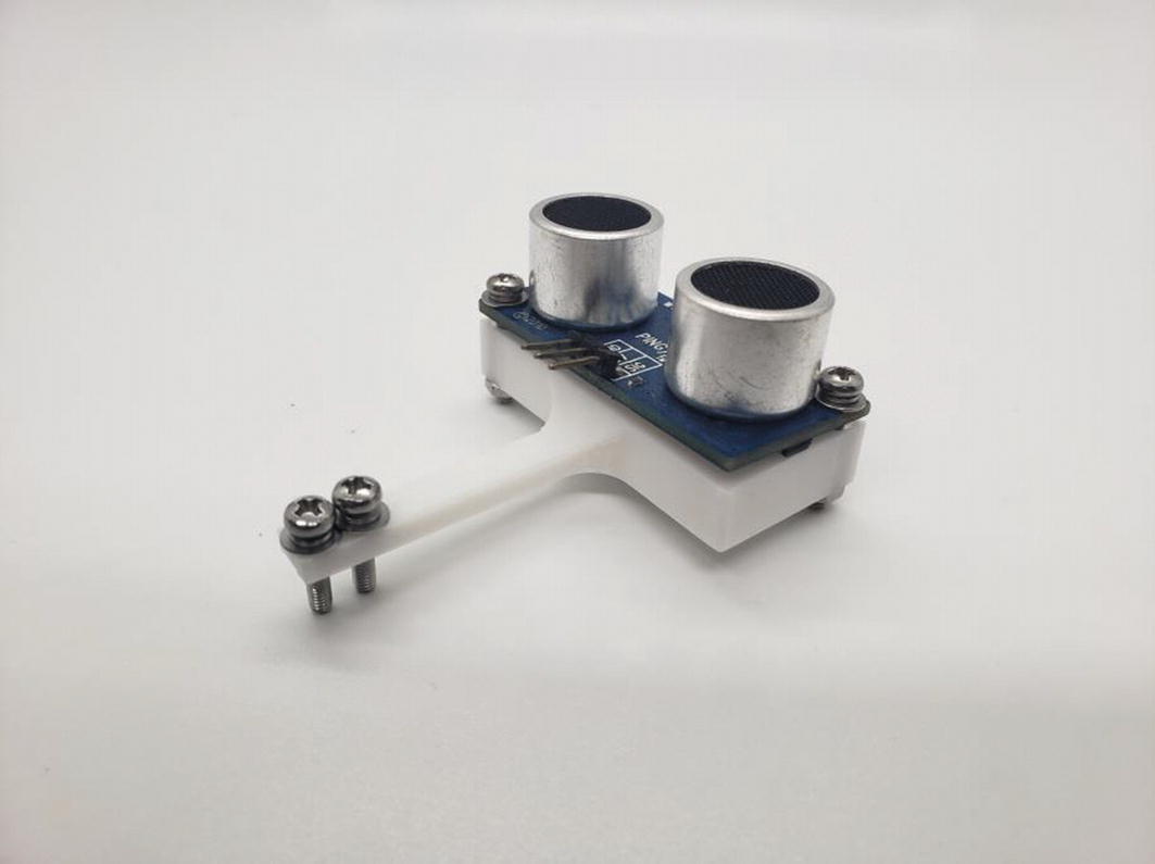
Attach the Ultrasonic Sensor to the mount
- 7.
Attach the GPS module to the GPS mount using a small piece of Velcro. Use scissors to cut the Velcro to size. See Figure 8-46.
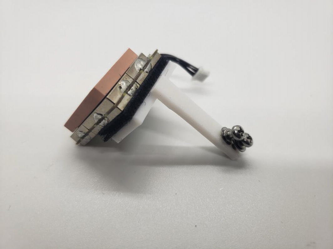
Attach the GPS module to the GPS mount using Velcro
- 8.
Attach the LCD to the LCD mount using two M2 12mm screws and two M2 nuts. See Figure 8-47.
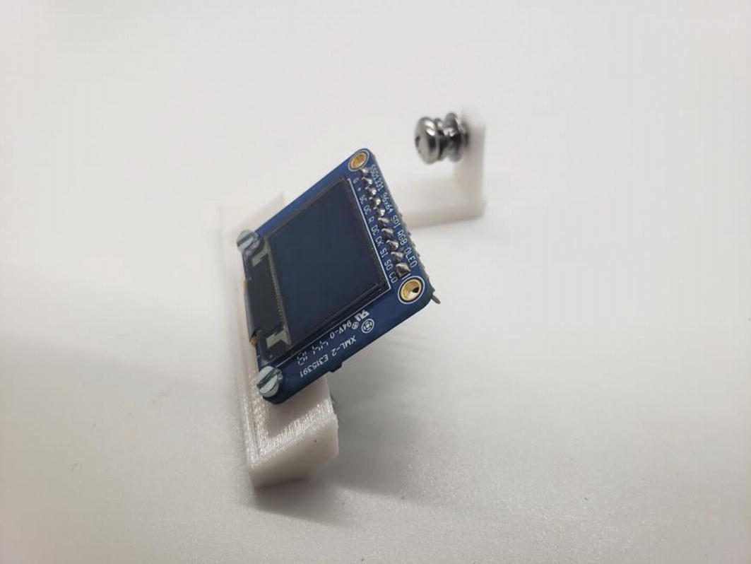
Attach the LCD to the LCD mount
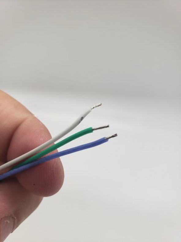
Cut off 1/8in insulation

Insert a wire and use pliers to gently squeeze the insulation crimp to hold the wire in place
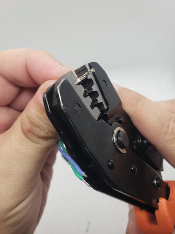
Crimp the contact onto the wire

Finished crimp

Insert crimped wire into 3 position housing
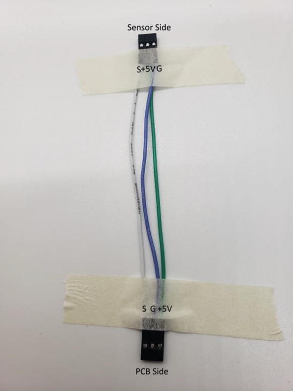
Make sure the connector has this pinout
- 10.
Create the wire harness for the LCD using 2 x 10 position dupont headers and 20 female dupont crimps. You will also need 10 x 3in 24 AWG stranded wire. See Figure 8-54. Use the same method to create the wiring harness as you did in the previous step.
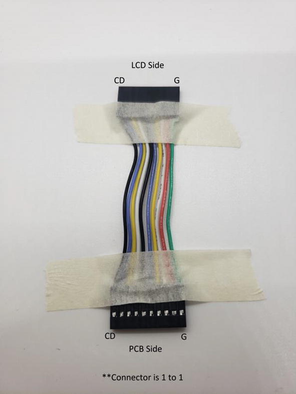
LCD cable
- 11.
Attach the Ultrasonic Sensor Mount to the chassis using 2 x M2 10mm screws and 2 x M2 nuts. See Figure 8-55.
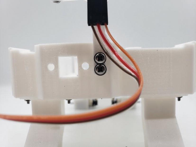
Attach the Ultrasonic Sensor Mount
- 12.
Put the battery into the battery holder and use the two zip ties to secure it to the NatBot chassis. See Figure 8-56.

Attach the battery to the chassis using two zip ties
- 13.
Attach the four JST cables to each of the four motors in the wheelbases and put them through the motor cable passthrough holes on the NatBot chassis. See Figure 8-57.
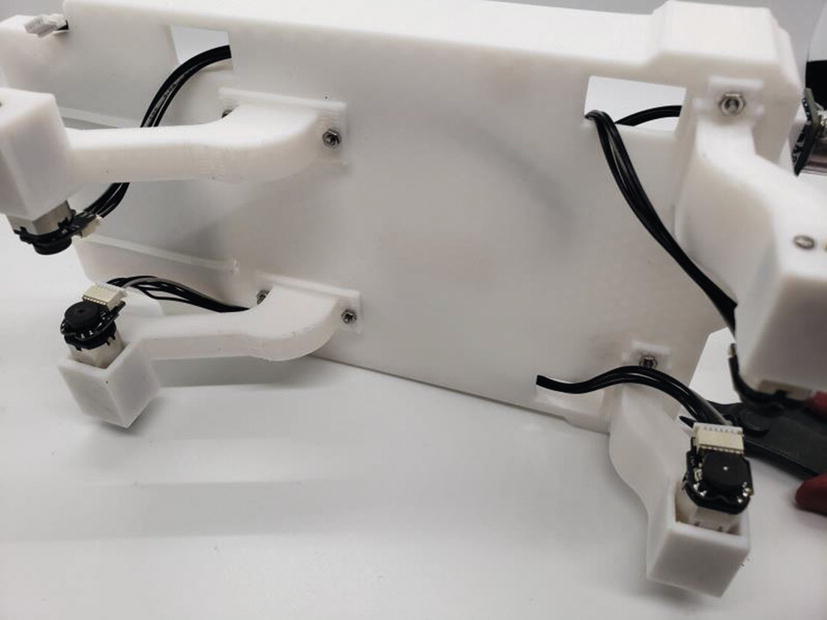
Attach the JST cables to the four motors
- 14.
Wrap each of the JST wire with a zip tie to make them a bit shorter. Do not tighten too much because you can break the cable. See Figure 8-58.

Zip tie the JST cables to shorten them

Attach the micro USB panel mount

Attach the panel mount to the MEGA 2560 Pro
- 16.
Attach the NatBot PCB to the NatBot chassis and use 3 x M5 screws to attach the PCB to the NatBot chassis. See Figure 8-61.
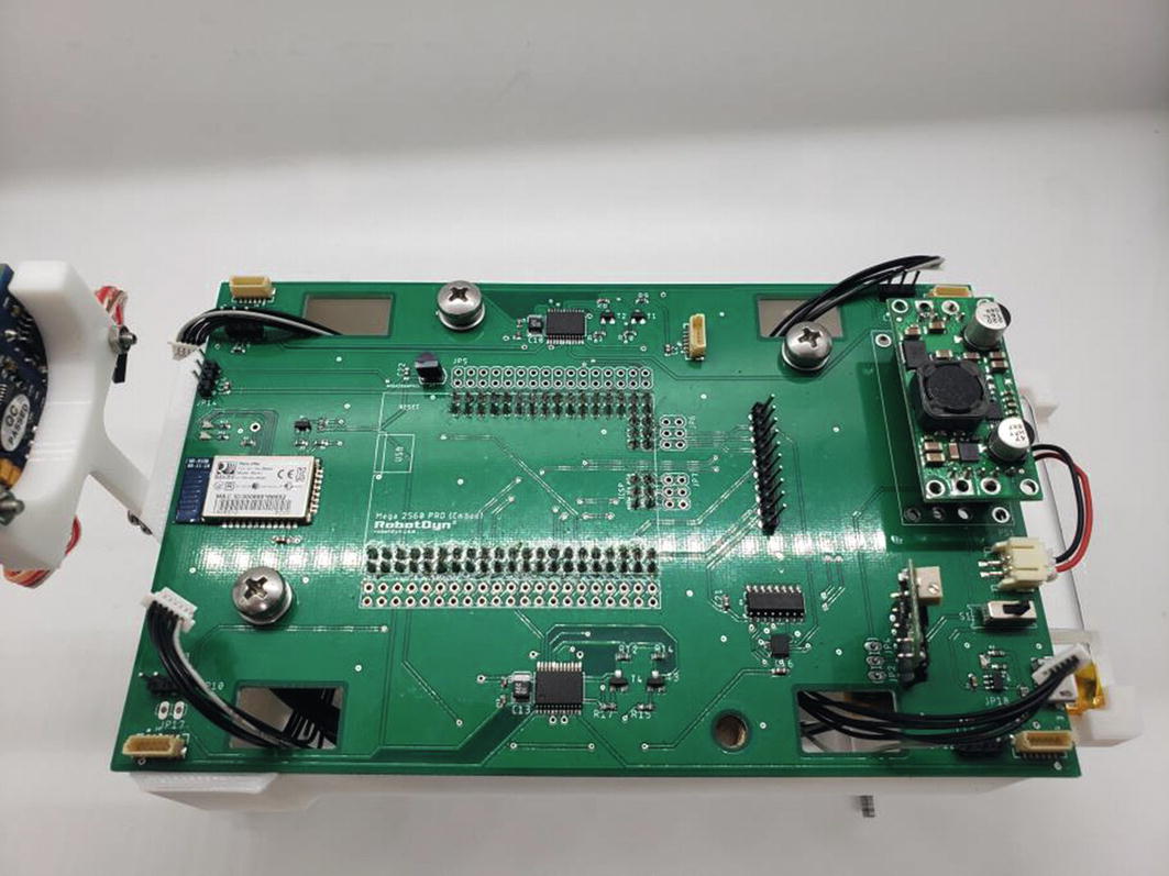
Attach the PCB to the chassis using three M5 screws
- 17.
Attach the LCD mount to the NatBot by using an M5 screw. See Figure 8-62.

Attach the LCD mount to the chassis
- 18.
Connect the other side of the LCD wiring harness to the PCB. Use a multimeter just to make sure all contacts are making the proper connection. See Figure 8-63.
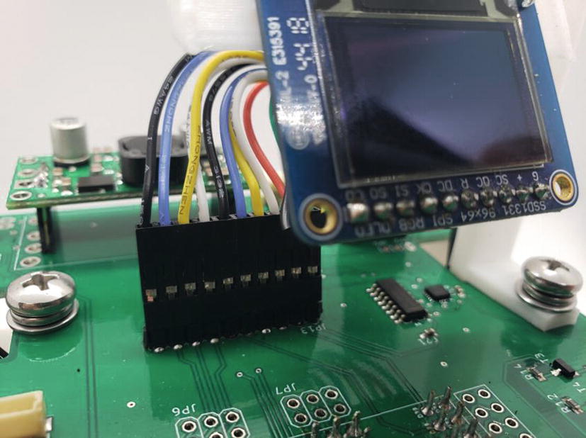
Attach the LCD connector to the PCB
- 19.
Attach the GPS mount to the chassis using 2 x M2 10mm screws and 2 x M2 nuts. See Figure 8-64.
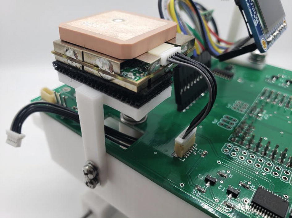
Attach the GPS mount to the chassis
- 20.
Attach the Ultrasonic Sensor wiring harness to the PCB. See Figure 8-65.

Attach the Ultrasonic Sensor cable to the PCB
- 21.
Connect all of the motor cables to the correct connector on the NatBot PCB. See Figure 8-66.

Attach the JST cables to the motor headers on the PCB
- 22.
Attach the motor couplers to the four motor shafts. See Figure 8-67.

Attach the motor couplers to the geared motor shafts
- 23.
Attach the four wheels to the motor couplers. See Figure 8-68.
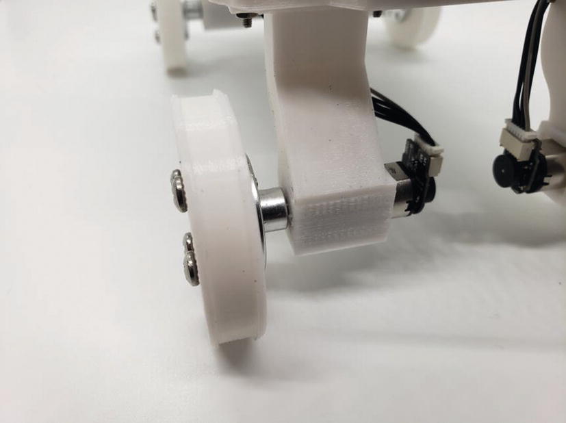
Attach the wheels to the couplers
- 24.
Add the 30mm rubber bands or gaskets to the NatBot wheels. See Figure 8-69.

Add 30mm rubber bands to give tires more traction
Well, that should be it for the assembly of the NatBot; the only thing left is to write some software that will bring the NatBot to life. See you in the next chapter.
Summary
Looked at the mechanical requirements for the NatBot chassis and mounts.
Brainstormed how we can bring this robot to life and make it look like a rover.
Took a look at all the important dimensions needed in order to create the NatBot chassis and mounts.
Went into what it will take to print each of these components.
Finally, we assembled the NatBot using a Bill of Materials (BOM).