
Power Distribution and Home Wiring
A.1 Power Distribution
Figure A.1 shows a typical power-distribution system found in the United States (region in California). The voltages listed are sinusoidal and are represented by their rms values. Note that the system in your area may look a bit different from the system shown here. Contact your local utility to learn about how things are set up in your region.
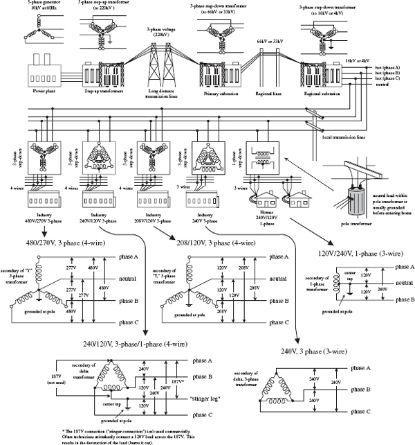
FIGURE A.1
As a note, ac is used in electrical distribution instead of dc because ac can be stepped up or down easily by using a transformer. Also, over long distances, it is more efficient to send electricity via high-voltage/low-current transmission lines. By reducing the current, less power is lost to resistive heating during transmission (lowering I within P = I2R lowers P). Once electricity reaches a substation, it must be stepped down to a safe level before entering homes and businesses.
Notice that industry typically uses three-phase electricity. The natural sequencing of the three phases is particularly useful for devices that perform rhythmic tasks. For example, three-phase electric motors (found in grinders, lathes, welders, air conditioners, and other high-power devices) often turn in near synchrony with the rising and falling voltages of the phases. Also, with three-phase electric power, there is never a time when all three phases are at the same voltage. With single-phase power, whenever the two phases have the same voltage, there is temporarily no electric power available. This is why single-phase electric devices must store energy to carry them over these dry spells. In three-phase power, a device can always obtain power from at least one pair of phases.
The simple generator shown in Fig. A.2 can be used to generate single-phase voltage. As the magnet is rotated by a mechanical force, a voltage is induced within the two coils (spaced 180° apart) that yields a single sinusoidal voltage. The output voltage is usually expressed as an rms voltage (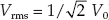 ).
).
FIGURE A.2
In the three-phase generator, three separate voltages are generated by using three different coils spaced 120° apart. As the magnet rotates, a voltage is induced across each of the generator’s coils. All the coil voltages are equal in magnitude but are 120° out of phase with each other. With this generator, you could power three separate loads of equal resistance, or you could drive a three-phase motor with a similar coil configuration; however, this requires using six separate wires. To reduce the number of wires, there are two tricks that can be used. The first trick involves rearranging the three-phase coil connections into what is called a delta connection—which yields three wires. The second trick involves rearranging the coil connection into what is called a Y connection—which yields four wires. Here are the details.

A Y configuration is made by connecting one end of each of the generator’s coils together to form what is called the neutral lead. The remaining three coil ends are brought out separately and are considered the “hot” leads. The voltage between the neutral and any one of the hot lines is called the phase voltage Vp. The total voltage, or line voltage VL, is the voltage across any two hot leads. The line voltage is the vector sum of the individual phase voltages. In a Y-loaded circuit, each load has two phases in series. This means that the current and voltage through and across a load must be determined by superimposing the phase currents and phase voltages. One way to do this is to make a phasor diagram, as shown in the figure. For practical purposes, what is important to note is the line voltage is about  times the phase voltage. Also, the line currents are 30° out of phase with the line voltages. When a neutral is used, the line currents and line voltages are equal to the individual phases from the generator. No current flows in the neutral when the loads are equal across each phase (balanced load).
FIGURE A.3

A delta connection is made by placing the three-phase generator’s coils end to end, as shown in the figure. Because the delta configuration has no neutral lead, the phase voltages are equal to the line voltages. Again, like the Y configuration, all line voltages are 120° out of phase with each other. However, unlike the Y configuration, the line currents (I1, I2, I3) are equal to the vector sum of the phase currents (IA, IB, IC). When each of the phases are equally loaded, the line currents are all equal but 120° apart. The line currents are 30° out of phase with the line voltages, and they are times the phase currents.
FIGURE A.4
In the United States, three wires run from the pole transformer (or “green box” transformer) to the main service panel at one’s home. One wire is the A-phase wire (black in color), another is the B-phase wire (black in color), and the third is the neutral wire (white in color). (Figure A.5 shows where these three wires originate within the pole/ green box transformer.) The voltage between the A-phase and B-phase wires, or the “hot to hot” voltage, is 240 V, while the voltage between the neutral wire and either A-phase or B-phase wire, or the “neutral to hot” voltage, is 120 V. (These voltages are nominal and may vary from region to region.)
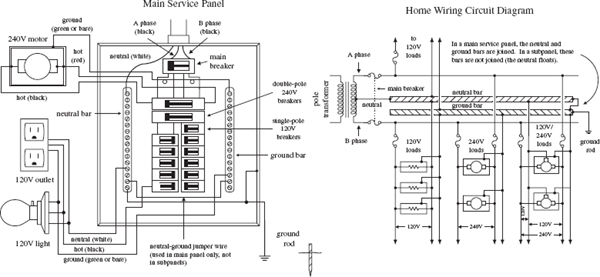
FIGURE A.5
At the home, the three wires from the pole/green box transformer are connected through a wattmeter and then enter a main service panel that is grounded to a long copper rod driven into the ground or to the steel in a home’s foundation. The A-phase and B-phase wires that enter the main panel are connected through a main disconnect breaker, while the neutral wire is connected to a terminal referred to as the neutral bar or neutral bus. A ground bar also may be present within the main service panel. The ground bar is connected to the grounding rod or to the foundation’s steel supports.
Within main service panels, the neutral bar and the ground bar are connected together (they act as one). However, within subpanels (service panels that get their power from the main service panel but which are located some distance from the main service panel), the neutral and ground bars are not joined together. Instead, the subpanel’s ground bar receives a ground wire from the main service panel. Often the metal conduit that is used to transport the wires from the main service panel to the subpanel is used as the “ground wire.” However, for certain critical applications (e.g., computer and life-support systems), the ground wire probably will be included within the conduit. Also, if a subpanel is not located in the same building as the main panel, a new ground rod typically is used to ground the subpanel. Note that different regions within the United States may use different wiring protocols. Therefore, do not assume that what I am telling you is standard practice where you live. Contact your local electrical inspector.
Within the main service panel, there are typically two bus bars into which circuit breaker modules are inserted. One of these bus bars is connected to the A-phase wire; the other bus bar is connected to the B-phase wire. To power a group of 120-V loads (e.g., upstairs lights and 120-V outlets), you throw the main breaker to the off position and then insert a single-pole breaker into one of the bus bars. (You can choose either the A-phase bus bar or the B-phase bus bar. The choice of which bus bar you use only becomes important when it comes to balancing the overall load—more on that in a second.) Next, you take a 120-V three-wire cable and connect the cable’s black (hot) wire to the breaker, connect the cable’s white (neutral) wire to the neutral bar, and connect the cable’s ground wire (green or bare) to the ground bar. You then run the cable to where the 120-V loads are located, connect the hot and neutral wires across the load, and fasten the ground wire to the case of the load (typically a ground screw is supplied on an outlet mounting or light figure for this purpose). To power other 120-V loads that use their own breakers, you basically do the same thing you did in the last setup. However, to maximize the capacity of the main panel (or subpanel) to supply as much current as possible without overloading the main circuit breaker in the process, it is important to balance the number of loads connected to the A-phase breakers with the number of loads connected to the B-phase breakers. This is referred to as balancing the load.
Now, if you want to supply power to 240-V appliances (e.g., ovens, washers, etc.), you insert a double-pole breaker between the A-phase and B-phase bus bars in the main panel (or subpanel). Next, you take a 240-V three-wire cable and attach one of its hot wires to the A-phase terminal of the breaker and attach its other hot wire to the B-phase terminal of the breaker. The ground wire (green or bare) is connected to the ground bar. You then run the cable to where the 240-V loads are located and attach the wires to the corresponding terminals of the load (typically within a 240-V outlet). Also, 120-V/240-V appliances are wired in a similar manner, except you use a fourwire cable that contains an additional neutral (white) wire that is joined at the neutral bar within the main panel (or subpanel). (As a practical note, you could use a fourwire 120-V/240-V cable instead of a 240-V three-wire cable for 240-V applications—you would just leave the neutral wire alone in this case.)
As a note of caution, do not attempt home wiring unless you are sure of your abilities. If you feel that you are capable, just make sure to flip the main breaker off before you start work within the main service panel. When working on light fixtures, switches, and outlets that are connected to an individual breaker, tag that breaker with tape so that you do not mistakenly flip the wrong breaker when you go back to test your connections.
A.4 Electricity in Other Countries
In the United States, homes receive a 60-Hz, 120-V single-phase voltage, whereas industry typically receives a 60-Hz, 208-V/120-V three-phase voltage. Most other countries, on the other hand, work with a 50-Hz, 230-V single-phase voltage and a 415-V three-phase voltage. Now, if you were to take a U.S.-built 120-V, 60-Hz device over to Norway—where 230 V is used—and plug that device directly into the outlet (you would need an adapter to do this—their outlets look different), you run a risk of damaging the device. Some devices may not “care” about the voltage and frequency differences, but others will. You could use a converter (transformer plug-in device) to step down the voltage from the outlet, but you would still be stuck with 50 Hz. The 10-Hz difference will not affect most devices, but other devices, such as TVs and VCRs, may not function properly.
Here’s a listing of single-phase voltages found in some countries. Note the plug types.
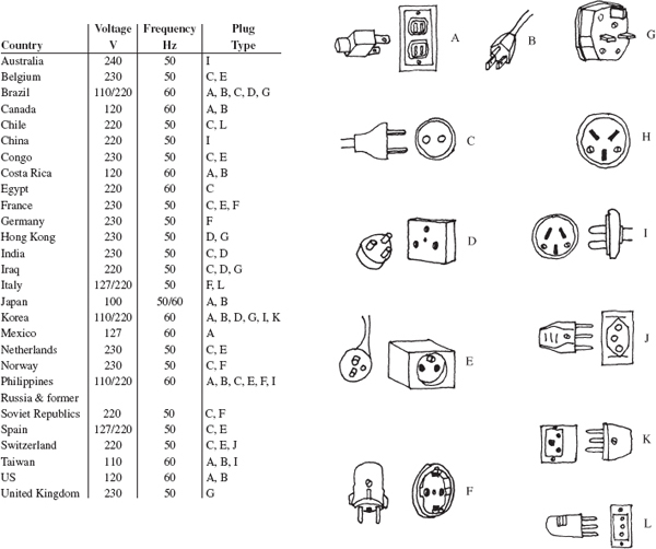
FIGURE A.6
..................Content has been hidden....................
You can't read the all page of ebook, please click here login for view all page.