
Chapter 10. Infrastructure Matters
The road is built; the tires ready to screech—game on!
In everyday life, you may hear the question “How good is the infrastructure?” This question is applicable to a wide array of disciplines—from politics to transportation to health care and many more. Software development is not too different in this regard. The hardware infrastructure—the network, hosting, and servers—is among the most critical components that are instrumental in making a system operational; that is, for it to be deployed, accessible, and usable. Your system’s ability to support its nonfunctional requirements relies heavily on the shape, size, and placement of the infrastructure components.
This chapter briefly explores some of the essential considerations regarding hosting, which promotes better efficiency and utilization of the compute (processor speeds and families, processor types, memory) and storage resources; how availability and reliability measures can be met through infrastructure; network characteristics that provide optimal bandwidth; and also metrics to consider while deriving the capacities of some of the key architecture building blocks of IT Systems. We also demonstrate how some of the infrastructure considerations influence the deployment model for the Elixir system.
Note: The term “compute” is used often in this chapter to denote different types of processors for dedicated functions, processors with different rates for processing instructions, and the capacity of the processor family along with the memory specifications.
And practically speaking, you, as a solution architect, need to know enough to be able to oversee the design of the right-sized infrastructure for any of your solutions. To be able to wear the infrastructure hat and facilitate design discussions around capacity sizing and hosting will make you even more formidable. You’ll have a quiver full of architecture arrows!
Before jumping in, look at these two formal disclaimers for this chapter:
• This chapter, by no means, makes any claim to provide an exhaustive treatment of infrastructure architecture as a discipline. The aim is to provide the solution architect with some of the essential considerations that must be addressed for most systems.
• The intent of this chapter is not to make you an infrastructure architect. However, it is intended to provide you with some key concepts around some of the infrastructure areas that commonly recur in most medium to complex IT Systems.
Why We Need It
The need for a well-defined and appropriately architected infrastructure for any IT System is paramount. In the yin and yang analogy, while a system’s functionality ascertains its expected behavior (the yin), the infrastructure platform on which the system operates (the yang) ensures that the expected behavior is made available in a timely, responsive, and resilient (to failure) manner. The salient point here is that an IT System has both a functional and a nonfunctional component, and only when they complement each other will the use of the system be effective.
The options around infrastructure have significantly increased with the introduction of cloud computing and the many opportunities around federation and virtualization of computing. Network technologies have also seen tremendous advancements; technologies such as IBM Aspera® (IBM “Aspera high-speed transfer”) use breakthrough transfer protocols, which use the existing infrastructure, to handle the largest data requirements at maximum speed, regardless of data type, size, distances, or network conditions. The infrastructure buzz is real, and companies are already harnessing significant returns on investment (ROIs) by adopting the right infrastructure technologies. The fulfillment of the physical operational model (see Chapter 8, “The Operational Model”) requires commensurate diligence in designing the system’s IT infrastructure.
From a business perspective, a study conducted by IBM Institute of Business Value (n.d.) revealed that “while 71% of all modern organizations say that IT infrastructure plays an important role in enabling competitive advantage or optimizing revenue and profit, only less than 10% report that their IT infrastructure is fully prepared to meet the demands of modern day computing demands around mobile technology, social media, big data and cloud computing.” The role of infrastructure assumes even greater significance with the advancement in computing paradigms.
Seat belts fastened? Off we go!
Some Considerations
As a practical solution architect, you have to always keep one hand on the infrastructure steering wheel. The direction you’re heading should be correct!
The following sections focus on five essential aspects of infrastructure:
• Networks
• Hosting
• High availability and fault tolerance
• Disaster recovery
• Capacity planning
Networks
A network infrastructure model is influenced by the size of the site or the data center, the volume and frequency of data transfer, and a subset of the service-level agreements (SLA) around performance, throughput, and system uptime. Although data centers abstract the underlying network models, topology, and physical interconnects, this section briefly touches upon some of the high-level fundamentals that help influence and determine the network topology.
The network model has been standardized to follow a three-tier hierarchical model consisting of the Access, Distribution, and Core layers (see Figure 10.1):
• Access layer—This layer provides network access to the users and devices. The number of system users typically determines whether a switch (which is faster and more expensive) or a hub (which is slower and cheaper) is used. Both wired and wireless access to the devices and users may be provided.
• Distribution layer—This layer mediates between and provides the Access layer entities with the connectivity to the Core layer. It also facilitates communication between multiple Access layers. Routers and multilayer switches are typically used as the network devices at this layer. The network devices are typically deployed in pairs to ensure redundancy and, hence, reliability of the network.
• Core layer—This layer provisions the application services and storage services. The network devices at this layer are responsible for aggregating multiple Distribution layer networks, facilitate their interconnections, and also provide very high speed network access for and between the services offered at this layer.
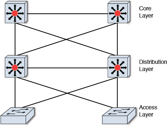
Cisco (2008, April 15) provides more details on the three-tier hierarchical network model.
The size and complexity of a set or data center determines the level of sophistication (around, for example, redundancy, reliability, bandwidth, processing capacity, and distribution topology) of the network components and devices (that is, hubs, switches, multilayer switches, switch blocks, routers, and network cabling) to support the desired network workload to meet the required SLAs.
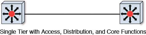
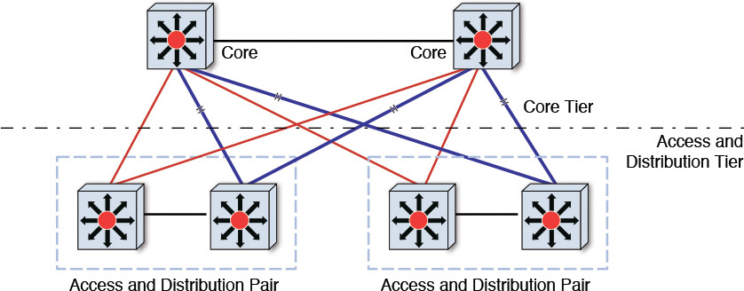
Any standard data center is expected to provide capabilities at all three layers. In a standard setup, the functions of all three layers are placed in a single switch, and popular wisdom advocates that, except in the most trivial of network topologies, there is at least a pair of such switches to support basic network redundancy (see Figure 10.2). However, in scenarios in which the infrastructure components (that is, servers, server interconnections, and so on) outgrow the capacity of a switch, the network topology is typically broken down into multiple tiers (as opposed to all functions being in a single switch). With cost, economies of scale, and SLAs in mind, the Core layer gets a dedicated switch, while the Access and Distribution layers continue to be supported by a single switch (see Figure 10.3). In such a multitier network topology, there are more connections and, hence, commensurate opportunities exist to foster redundancy and reliability at the network level for the IT System.
The network layer can also be used to implement segmentation, ensuring that the infrastructure resources are shared in a manner that is secure and appropriately apportioned according to utilization requirements. Access layer segmentation is typically implemented using a virtual local area network (VLAN), which enables multiple groups of Access layer devices and servers to share a single switch. For the Distribution and Core layers, although quite a few options exist, the most commonly used technique is based on MPLS/VPN technology. Virtual firewalls can also be attached (that is, plugged into the switches at the Distribution layer) if an additional level of user and application security is required.
You typically create a virtual data center by using VLANs in the Access layer, virtual firewalls in the Distribution layer, and MPLS/VPN at the Core switches.
Quality of Service (QoS) is a key metric used to measure the efficacy of the network backbone. QoS is a set of techniques to manage bandwidth, delay, jitter, and packet loss within the network. It is often used to influence a prioritization scheme for serving a class of applications over others. The trick is to differentiate the network traffic by the class of users accessing a class of applications that are differentiated by a set of service-level requirements, among other criteria.
If you have not had deep network architecture and design experience, relax! Having an understanding of the concepts shared in this section will help you set the stage, facilitate, and ask pertinent questions of the network or infrastructure architect to ensure that the appropriate due diligence and rigor are applied to design the network layer. In this era of cloud computing when networks are offered through an As-a-Service model, networking has become more about picking your choice rather than having to build everything on your own.
Hosting
The main objective of hosting is to ensure that fragmented, inefficient islands of computing are not fostered; instead, a virtualized, efficient, resilient, and secure infrastructure platform is leveraged to support dynamic provisioning of infrastructure services and its associated services management.
Although traditional enterprise IT, on-premise, and in-house data centers are not going to fade into obsolescence, cloud computing is abundant in its hype, focus, and buzz; it is positioned to be the hosting strategy for most enterprises. According to Gartner (2009), “Cloud is emerging at the convergence of three major trends: service orientation, virtualization and standardization of computing through the Internet.” In its current state in 2015, this prediction is not only spot on, but cloud computing is also poised to take off more aggressively in the upcoming years. Cloud hosting started with two broad categories of cloud-based hosting: namely, private clouds and public clouds. However, hybrid cloud topology and deployment models have become so commonplace that it is now safe to consider three cloud hosting models: public, private, and hybrid (of public and private).
Choosing the hosting strategy often may turn out to be a time-consuming and detailed undertaking. The “Cloud Hosting Models” sidebar may provide some hints to help guide you.
From a hosting architecture perspective, the physical components (that is, the servers, network, hardware, compute, storage, and facilities where they all get hosted) are foundational; the traditional IT enterprise has been using them for decades. Where hosting has taken off, in an exponential manner, is with its adoption of the As-a-Service model. The cloud model abstracts the foundational components and exposes and offers their capabilities As a Service for consumption; the consumers can remain ignorant of their physical location and placement—the boon of virtualization! Speaking of which, there are three layers of virtualization in the cloud hosting architecture, each with increasing levels of abstraction; that is, the higher you go up the three layers, the less you know or care about the physical components. Although cloud service providers such as IBM, Google, and Amazon are continuously innovating and adding higher levels of As-a-Service offerings, there still are three foundation virtualization layers.
Let’s look further at the three layers of virtualization: Infrastructure as a Service (IaaS), Platform as a Service (PaaS), and Software as a Service (SaaS).
• IaaS—Physical resources: Servers, compute, network, hardware, storage, and data centers are virtualized and available for quick provisioning and use. In effect, the compute, storage, and interconnects (network, data center backbone) are virtualized. The virtualized environment is typically offered as virtual machines (VMs) that are owned, hosted, managed, and maintained by the cloud hosting provider. IBM SoftLayer® (Softlayer n.d.), Amazon EC2 (Amazon n.d.), Google Compute Engine (Google n.d.), and Azure Virtual Machines (Microsoft n.d.) are examples of IaaS service providers.
• PaaS—Middleware components: Databases, development tooling for application development and orchestration, runtime environment (for example, .NET, J2EE runtime), and application deployment tooling, all of which support a complete end-to-end application development, test, and deployment platform. The platform, exposed As a Service, builds on top of and abstracts the underlying hardware, network, and server components; that is, the IaaS layer. The platform facilitates an almost instantaneous subscription to a complete environment tailored to the user’s preferences and choices. The user is not tied to these choices and has the freedom to subscribe to more (or less) compute and environment capabilities on demand. IBM Bluemix™ (IBM n.d.) and Google App Engine (Google n.d.) are great examples of PaaS offerings as of this writing.
• SaaS—Application: This layer provides complete end-to-end applications exposed and accessible through a multitude of delivery channels, such as desktop browsers and native mobile applications. The user interfaces, data, and middleware components along with the storage, network, servers, and compute are all hidden from the user and managed by the hosting service provider. Custom-built applications; CRM, ERP, and HR applications; industry-specific applications; and business processes are examples of SaaS offerings.
Innovative companies and solution providers are pushing the SaaS envelope and chartering specialized offerings such as Solution as a Service and Analytics as a Service. Other similar or more innovative offerings are also viable and are highly probable to come up.
From a hosting standpoint, both traditional enterprise IT Systems and modern cloud-based hosting solutions have one thing in common: the need for physical resources such as server, storage, hardware, compute, middleware, networks, and related peripherals. They also must exercise the same rigor to size and procure, install, and configure these resources. However, that is where the commonality ends. The cloud-based hosting philosophy takes off from there—riding on the paradigm of virtualization, fostering ease of use, minimal to zero upfront cost and setup time (for end users), and no management overhead (now, which enterprise IT department wouldn’t love that?!). With the ease of usability and ramp-up, dished out to the IT community, someone has to do all the heavy lifting (“free and easy” is relative!) and charge a premium in order to make a living. There is an entire discipline around cloud services management that is pivotal for the cloud-based computing business to flourish.
Cloud Management Services (CMS) is an entire discipline unto itself; I do not provide an exhaustive treatment of it here. Rather, I touch on the aspects that are, in my experience, not only the most practical and common but also are the most frequently touched-on discussion topics related to solutioning. A solution architect needs to be able to participate in such discussions, if not contribute to the same. Some of the topics are shown in Table 10.1.
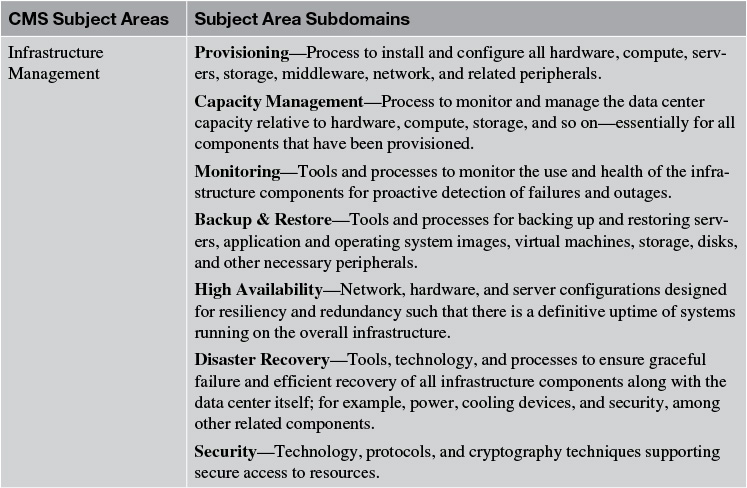
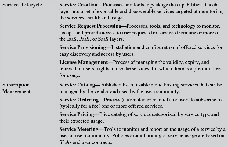
Table 10.1 An Illustrative (Not Exhaustive) List of Offerings and Features of a Typical Cloud Management Service
It should be quite evident by now that the real work is managed behind the scenes by the cloud service providers. Although the list of CMS features is not exhaustive, you, as a solution architect, should be able to ask a pertinent set of questions when working with, directing, and overseeing the infrastructure architect to ensure the appropriate hosting solution is designed and implemented for your solution. You might ask questions like these: Which PaaS features are offered by Vendor X? What are the different levels of SLAs supported for premium service? Are the subscription fees of Vendor X competitive in the marketplace? Asking these questions, and many more tough ones, should not be scary!
High Availability and Fault Tolerance
High availability (HA) defines the ability of an application to provide and adhere to a consistent uptime, either for the entire application or for its most critical parts, in a manner that is predictable and deterministic. It is the ability of the application to be tolerant to system faults and is a measure of its resiliency to system failures—an effort to move toward continuous operations. The terms high availability and fault tolerance are often used synonymously.
From an architecture standpoint, HA falls under the nonfunctional requirements, ensuring that the architecture supports the requirements around system uptime and resiliency criteria. A thorough assessment covering the operating systems, middleware, databases, storage, network, and applications is ideally required to identify, determine, and address the various points of system failures in the end-to-end system topology. The assessment may optionally include a component failure analysis, transaction flow monitoring through the infrastructure, and analysis of a real or potential outage, and it ultimately may influence the disaster recovery architecture and plan (which is the topic of the next section).
In a nutshell, the general technique to address a system’s HA architecture follows a few simple steps (but, of course, you need to pay attention to the details):
1. Identify the single points of failure (SPoF) in the system.
2. Assess the probability of the SPoF and its cost to fix or recover.
3. Introduce redundancy in the component that is deemed to be a critical SPoF.
4. Develop a detailed diagrammatic (often geeky and esoteric looking) representation depicting the HA system topology.
Note: I have not included cost impact analysis as a part of the preceding steps. While I could argue that it is not an aspect of architecture, there is no discounting the effects of cost and budget on a solution’s practicality of implementation in an organization.
Table 10.2 identifies the most commonly addressed SPoFs along with, generally speaking, their relative cost to fix.
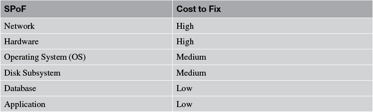
In the previous section, you learned about some potential network architectures that can aid in minimizing or avoiding its failure. In the following sections, I highlight some techniques to support fault tolerance and introduce HA for the SPoFs identified in Table 10.2.
Let me make a few simplifying assumptions to illustrate some of these techniques:
• A unit of physical address space is defined by a single virtual machine that runs a copy of an operating system.
• All of the application components run on a single operating system.
• The cardinality of redundancy is two and not too many!
• The operating system is Linux.
• The web application serves static content and runs on an HTTP server.
Hardware HA
System failure may occur at the physical hardware. If the hardware (on which the operating system and the application components runs) fails, you have a problem.
Redundancy at the hardware level can be implemented in two ways. In the first approach, you can have two (or more) physical machines built with the exact same hardware architecture and configuration as well as the software and applications that run on it. In such a scenario, there should be an external means to switch from one physical machine (the primary) to another in the event the primary physical machine fails. The second approach is a bit more innovative and much more cost effective; it employs the general principles of virtualization. The approach uses a technique called logical partitioning (LPAR) that packages a subset of the computer’s hardware resources and virtualizes the same as though it is a separate compute environment. Each separate LPAR hosts its own copy of the operating system and can be used independently. Of course, a management component at the physical machine level manages the LPARs and also manages the traffic between the LPARs. Resources are either statically allocated and remain fixed for each of the LPARs or may be dynamically allocated based on computational needs; the dynamic variations are often called dynamic LPARs, or DLPARs.
The LPARs are massively cost effective because they run multiple environments—for example, development, test, and production environments—in a single physical machine. They also can be used to support resiliency to hardware failures through dynamic resource allocation based either on internal intelligence or on external triggers.
IBM has been the pioneer of LPAR technology. IBM mainframes run exclusively in LPAR mode running on the z/OS® operating system. With the introduction of the POWER5® architecture and higher-end processors, even the midrange IBM pSeries supports hardware virtualization features. Fujitsu, with its PRIMEQUEST line of servers, and Hitachi Data Systems, with its CB2000 and CB320 blade systems, also provide support for LPAR.
Note: In some cases LPAR configuration changes may require a reboot of the LPAR. So there is always a catch!
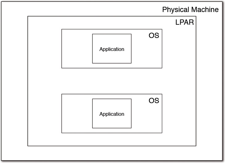
Operating System HA
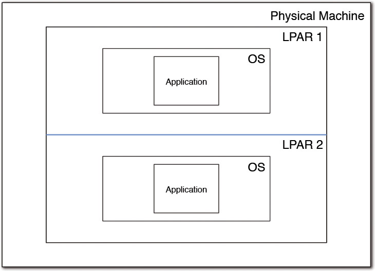
When multiple instances of the operating system run simultaneously, each hosting a replicated instance of the application, the OS SPoF can be addressed. A failure of the Linux server still allows the application to run on the other server and hence eliminates system downtime. There could be at least two topologies if the hardware configuration supports LPARs. In the first topology, which is an example of vertical scaling, a single LPAR can run multiple instances of the operating system. Meanwhile, in the second topology, which is an example of horizontal scaling, two or more different LPARs run the two or more instances of the OS, one on each LPAR.
While the second topology can take advantage of the hardware HA, the first topology requires that the server workload needs to be carefully designed. In one of the scenarios in the first topology, the two application instances can be configured to run concurrently and share the workload between them. In another scenario in the first topology, the two application instances may be configured to run in hot standby mode: one instance is active and serving the users, whereas the other is on standby mode and ready to run in the event the first instance goes down. If the underlying hardware architecture supports the sharing of all compute resources among all the virtual machines running the operating systems, the failure of one virtual server frees up all its compute and makes it available for the others to consume. In this case, no additional workload care is required. However, when the hardware architecture does not support resource sharing, each of the server instances must be appropriately sized and configured accordingly to pick up the entire workload with dedicated compute resources.
A tad complicated, isn’t it? Take a look at the two topologies shown in Figures 10.4 and 10.5, which can at least be worth the nearly 300 words I used in the preceding paragraphs!
Disk Subsystem HA
The disk subsystem is a critical element of the overall high availability of the solution. If the disk subsystem fails, any of the application’s persistence (that is, storage) requirements will not be met. Disk fault tolerance is implemented using the most commonly used disk redundancy technique called Redundant Array of Inexpensive Disks, or RAID. There are a multitude of configurations of the disk subsystem: RAID 0, RAID 1, RAID 5, RAID 6, and RAID 10. However, the two most commonly used ones, in practice, are the RAID 5 and RAID 10 configurations. For the sake of simplicity, assume no more than two, three, or four disk drives, depending on the RAID configurations. The actual number of disk drives can be more, however.
The most commonly used RAID configurations are as follows:
• RAID 0—Also called striping, RAID 0 uses a configuration in which the data is spread across (that is, striped) more than one disk. The data blocks (a unit of data that is read or written to and from a disk subsystem) are distributed in the disk drives, for example; only alternate data blocks are stored in each disk drive. This configuration offers no fault tolerance; the failure of a disk drive implies loss of data and should typically be used in systems where storage loss is noncritical. Figure 10.6 provides a depiction.
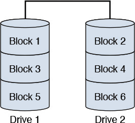
(Note: In Figure 10.6, the data blocks are striped; that is, distributed across multiple disk drives.)
Figure 10.6 A typical RAID 0 configuration with two disk drives.
• RAID 1—Also called mirroring, RAID 1 uses a configuration in which all the data is replicated (that is, mirrored) in more than one drive. The exact same copy of the data is stored in multiple drives; all data blocks are written to all drives. This configuration supports the redundancy required at the disk drive level and is suited for use in systems where storage loss is critical and may not be acceptable. Figure 10.7 provides a depiction.
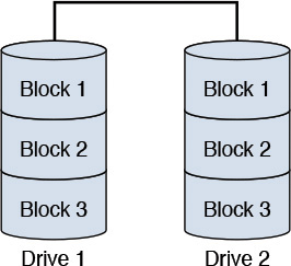
(Note: In Figure 10.7, the data blocks are mirrored; that is, replicated across multiple disk drives.)
Figure 10.7 A typical RAID 1 configuration with two disk drives.
• RAID 5—RAID 5 uses a configuration that combines striping with a technique called parity checksum (see the “Parity Checksum” sidebar later in this chapter). This configuration requires three or more disk drives. A data block is striped (that is, broken down into constituent blocks), and each block is written to different disk drives. The parity checksum of all the data is computed and written randomly to any one of the existing disk drives. The parity checksum is used, if required, to calculate the data in one of the data blocks in the event that the data block is no longer available. This configuration not only allows data to be available in the event that one disk drive fails but also allows the data on the failed drive to be recovered (through the parity checksum calculations). Keep in mind that access to data becomes slower in the event of a disk failure owing to parity checksum computation needs. Figure 10.8 provides a depiction.
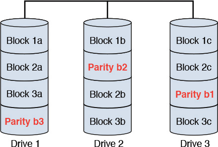
(Note: In Figure 10.8, the data blocks are striped across the disk drives along with parity bits for each block.)
Figure 10.8 A typical RAID 5 configuration with three disk drives.
• RAID 6—RAID 6 is similar to the RAID 5 configuration with the added sophistication of maintaining two (or more) copies of the parity bit in separate drives. With the parity data also being redundantly available, this configuration has the potential of surviving two failures happening at overlapping times. Figure 10.9 provides a depiction.
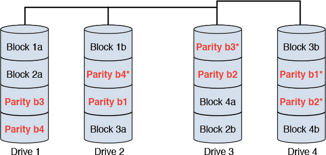
(Note: In Figure 10.9, the data blocks are striped, and the parity bits are mirrored across disk drives.)
Figure 10.9 A typical RAID 6 configuration with four disk drives.
• RAID 10—RAID 10 is a hybrid of RAID 0 and RAID 1 configurations combining the speed of access of RAID 0 striping with the redundancy of RAID 1 mirroring. It can also be thought of as mirrors that are striped. This configuration not only provides complete data redundancy (through mirroring) but also is efficient in data access and transfer (through striping). Figure 10.10 provides a depiction.
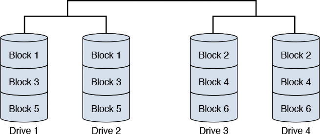
(Note: In Figure 10.10, the data blocks are striped as well as mirrored across multiple disk drives.)
Figure 10.10 A typical RAID 10 configuration with four disk drives.
It is very important to note that each RAID configuration not only has different levels of fault tolerance, or lack thereof, but also varies, often significantly, in its overall read-write performance and cost of implementation. While I don’t get into a detailed analysis and discourse of the “whys” of performance and cost here, let me just state the following:
• Striping, in general, increases the overall throughput and performance of the disk subsystem, whereas mirroring, in general, facilitates fault tolerance in the event of one or more disk drive failures.
• RAID 1 is the simplest of configurations with the greatest cost of drive capacity usage (for example, in the case of two disk subsystems, it can use only 50 percent of the total disk capacity owing to full mirroring across drives).
• RAID 5 and its use of the parity checksum not only make disk writes slower (parity checksums need to be calculated) but also pay a penalty in disk rebuilds (owing to the parity computations). The cost of disk capacity usage is better than that of RAID 1 and gets better with a higher number of disks (the percentage of disk space usage increases).
• RAID 6 configurations are quite popular, owing to its ability to tolerate multiple simultaneous disk failures.
• RAID 10 is the most costly solution and, if affordable, is often the best solution.
While you, as the solution architect, may not be expected to be the jack-of-all-infrastructure-matters (certainly not an expert on the disk subsystem, at least), having a good understanding and appreciation for the different RAID configurations, coupled with the nonfunctional requirements around system performance, would put you in a powerful position to facilitate important disk-related design decisions. Your value as a solution architect knows no bounds!
Database HA
High availability of database systems is often the most commonly seen scenario. At the end of the day, the data and computational results have to be persisted somewhere, with minimal to zero loss of information. Not having a database available during system operations is not a good story to tell.
Database technology has been around for many decades; it has been perfected and hardened over the years. Although the fundamental theories of database management systems still apply, vendors have developed innovative, specialized, and differentiated capabilities to win the competitive race toward a monopoly. HA solutions vary from one vendor to another and often quite dramatically as proprietary techniques and technologies are being applied. As an example, IBM DB2® uses its proprietary High Availability & Disaster Recovery (HADR) (IBM Redbook 2012) and Tivoli® System Automation (TSA) technologies to implement automatic failover between multiple instances of the database server. Oracle, on the other hand, practices what it calls the Maximum Availability Architecture (MAA) (Oracle 2011), which is based on Oracle’s proprietary HA technology—Oracle Flash technology, Automatic Storage Management (ASM), among a slew of other related technologies. Other vendors use their own versions of HA implementation. The bottom line is that most vendors have a pretty robust HA solution; the choice of vendor product will dictate your database’s HA approach.
Application HA
The application can be configured to work in a clustered environment. The two most common cluster configurations are the ones in which the first variation has both of the application instances (primary and secondary) simultaneously active. The second variation has one instance (the primary) active at any time and the second instance (the secondary) in passive mode, ready to be brought up and activated.
In the first variation, the primary processes the requests while the secondary has a heartbeat exchange with the primary. As long as the heartbeat is healthy, only the primary keeps processing the requests. When the heartbeat fails, the secondary considers the primary to be down and immediately picks up the processing tasks in a way that is completely transparent to the user request. In the second variation, an external intermediary component is typically required; it first identifies the failure of the primary, activates the secondary, and starts routing the user requests to the secondary.
To summarize, it is important to note that HA and fault tolerance implementations often vary significantly between multiple vendor products. The product-specific HA implementation best practices and configurations are necessities that should influence the final HA topology of your system. While you should be well versed with the general techniques and approaches for each of the SPoFs, I highly recommend that you call on and rely on an infrastructure architect to come up with the final HA topology. Now, doesn’t that bring a big sense of relief?
Disaster Recovery
Disaster recovery (DR) establishes a process to develop, maintain, and implement plans that assist organizations in handling disasters or interruptions that make critical client and systems support unavailable for any period of time. The main constituents of a DR process are as follows:
• DR Plan—A plan that consists of the disaster recovery organization structure, the escalation process, an inventory of the critical applications along with their contact information, and alternate site details, among other processes that are collected, documented, stored, and shared.
• Communication Management Plan—A plan that manages the communication either within your organization or between your organization and your clients. It supports the execution of the organization’s business goals and strategies around disaster recovery.
• Application Recovery Plan—Process steps that need to be followed to support a rapid restoration of a critical application following a disaster or interruption. Each application has a unique plan identifying its points of failure, data backup and restoration processes, and the latest point in time until when the application may be restored.
• Maintenance Strategy—Periodic or simulated event-triggered reviews of disaster recovery plans put in place so that, when a disaster actually occurs, accurate plans and execution strategies are available to deal with this interruption.
DR does not typically fall under the purview of the solution architect and may or may not be considered as success criteria for the system architecture. Your interface with the DR team primarily occurs in the form of assistance in developing the Application Recovery Plan. The DR team may expect the solution architect to help identify the most critical applications, their points of failure, and their data backup and restoration needs.
Capacity Planning
Capacity planning is one of the last “points of attraction” (that is, activity of importance) in this tour through the infrastructure kingdom! By this time, the technology architecture, which is defined by the set of middleware product as well as the infrastructure, should be well defined; that is, the network and servers on which the middleware products and application components will not only be hosted but also communicating with each other. Each server, hosting a set of middleware components, needs to be capacity sized; that is, the amount of compute power and storage needs required to run the application components. Each application component has unique characteristics that ultimately drive the capacity and throughput needs of the server on which it is hosted. As an example, a web server that front-ends user requests needs to support a given number of concurrent user requests without compromising on expected latency for user request fulfillment. A database server that back-ends an application needs to support a given number of transactions (reads, writes, and so on), among other requirements, in a given unit of time without compromising on the transactional latency. The bottom line is that the nonfunctional requirements of the application primarily dictate the capacity of the servers on which certain middleware is hosted, supporting different application components.
Capacity planning—or I should say the outcome of a capacity-planning analysis—varies from one middleware product to another. As an example, for databases, the recommended compute and storage capacity for IBM DB2 could be different from the Oracle RDBMS (relational database management system). The reason may be attributed to the internal architectures of the middleware products.
This section describes three main components and discusses some of the most generic attributions that aid in the capacity-sizing analysis. I describe the web server, application server, and database server. Although I highlight the consideration factors that I believe to be imperatives, product vendors get the final say in the factors that they consider to be the most important to size their middleware appropriately. Yes, vendor product specialists and subject matter experts get to have the final say!
For the web server, the most commonly recurring factors to consider may be the following:
• Is the web server external (Internet) or internal (intranet) facing?
• What is the total number of users who will be accessing the web server?
• How many concurrent users will be accessing the web server?
• How many web pages will the web server serve?
• What is the average transaction size?
• Is the web traffic continuous, or does it come in bursts?
• Are there expected spikes in web traffic; for example, seasonal traffic?
• What is the distribution between static and dynamic web pages that are being served?
• For dynamic content, what is the nature (for example, multimedia, text, images, streaming data) and complexity of the generated content?
• What is the availability requirement for the web server serving the presentation components of the IT System?
• What is the expected growth (for example, number of users, number of served pages, type of content served) of the presentation components of the IT System?
• Do the user sessions require being stateful in nature?
The sizing should typically recommend the memory requirements for the underlying operating system, the application itself, and the cache size. It also provides the maximum number of child processes that may be spawned as well as the total disk space requirements. The vendor may choose to recommend additional criteria for optimal usage of its middleware products.
For the application server, the most commonly recurring factors to consider may be the following:
• How many concurrent users will require service?
• How many concurrent database connections must be supported across all database instances to which access may be required?
• How many applications or application components will be installed; that is, the total workload on the application server?
• How many applications will be active and concurrently accessed?
• What additional workloads will be installed on the same box or machine?
• What is the total size of the applications that are installed; that is, the application’s disk requirements?
• What is the total size of the applications that are simultaneously active?
• How active and busy will the active applications be; for example, their hit rate?
• Will session persistence be required? If so, what is the size requirement (that is, memory and disk space) of each session?
• What is the expected average and peak CPU utilization?
• Is the application server workload expected to be executed on a single machine, or is it expected to be shared among multiple machines or servers?
• Is vertical scaling (running multiple clones of the application server on the same box) a part of the deployment plan?
As the solution architect, you must decide or influence how the application workload may be distributed. As an example, consider whether all applications or application components will be hosted on a single server and a single instance or whether vertical or horizontal scaling will be required as a part of the operational model. The plans for application scaling, for expected server busy times, for hit rate variations, and for session requirements, among other parameters, are critical considerations to right size the servers.
For the database server, the most commonly recurring factors to consider may be the following:
• What is the complexity of the transactions; in other words, what are the query workload characteristics?
• How many concurrent transactions need to be supported?
• How many concurrent connections need to be available?
• What is the database size on which transactions will be executed?
• What is the size (smallest, largest, and average) of the tables?
• What is the ratio of read versus write (and delete) queries?
• What are the I/O (input, output) workload characteristics?
• What is the size of the raw data to be stored in the database?
• What are the availability requirements?
The sizing outcome typically recommends the processor and memory needs (or specifications) for the operating system and the database server, the disk space needed to store the data, the processing power of the hardware (using memory requirements as one of the inputs), and the database cache size and file system cache size (used in conjunction with the database cache).
For capacity sizing in general, there are some standard, well-accepted rules of thumb to calculate the metrics for specific genres of applications and middleware components. However, churning out the numbers is better left to the product vendors. The considerations are typically submitted to the specific product vendors either in the form of a questionnaire or through some tooling utility. Vendors are expected to provide the suggested compute and disk space requirements. They may also provide recommendations on the hardware and chip specifications for optimum performance, which is also an aspect of the compute. The hardware recommendations are more pervasive in the context of cloud computing; the cloud service providers typically have multiple different hardware machine specifications to choose from.
Capacity planning combines both art and engineering. Getting the exact or the most optimum capacity-sized infrastructure is often not realistic. When the system undergoes performance testing, quite a few surprises may surface. As a solution architect, you have to be amenable to accept these surprises, leave your ego outside the door, and keep an open mind. Both the project team and the project plan should factor in contingency to mitigate the risks that arise from the possibility of making mistakes.
Case Study: Infrastructure Considerations for Elixir
The technology architecture of the Elixir system leveraged three of BWM, Inc.’s existing technologies: Teradata, Microsoft SharePoint, and Crystal Reports. The rest of the products came from an integrated IBM software stack. There is no real value in explaining the inner guts of the capacity-planning techniques. Suffice it to say that, in this case, the IBM workload and capacity estimator tools were leveraged for each individual IBM middleware product. Similar techniques were used for Teradata, Microsoft SharePoint, and Crystal Reports to arrive at the computational capacities and server specifications for each node. You may want to refresh your memory with the architecture components of Elixir illustrated in Chapter 5, “The Architecture Overview,” as well as the operational model in Chapter 8.
Figure 10.11 depicts a technology architecture view of Elixir annotated with the hardware and server specifications for each of the nodes in the operational topology.
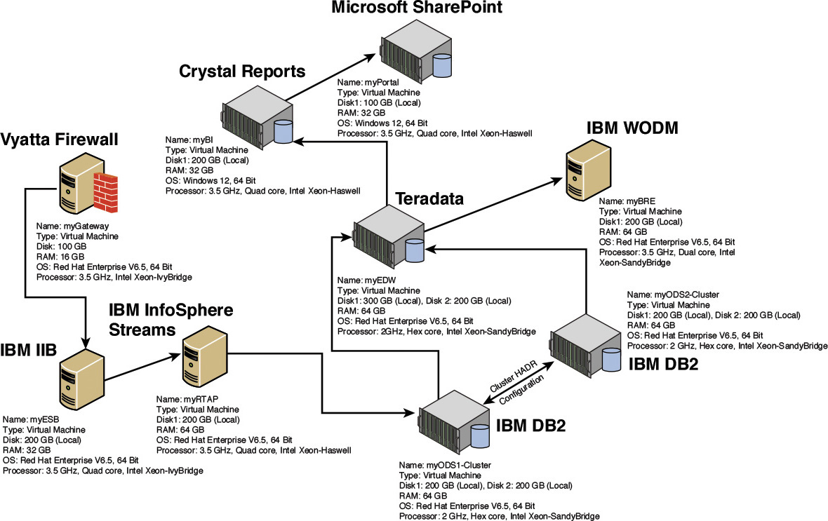
Note: Figure 10.11 uses a few abbreviations for product names. The actual names for the abbreviations are as follows:
• IBM IIB—IBM Integrated Information Bus
• IBM WODM—IBM WebSphere® Operational Decision Management
And now, the Elixir system has a technology architecture with capacity-sized hardware and middleware for the most critical components of the system.
Summary
This chapter covered a wide array of topics on infrastructure matters. If you have reached this far, you surely have realized that this chapter did not transform you into an authority on all infrastructure-related aspects that warrant focus and attention in any typical medium to complex IT Systems development initiatives. However, the purpose was to inform and provide you with the major disciplines and topics that are paramount to make your system functional and usable by happy users. The chapter covered five major areas of infrastructure: networks, hosting, high availability and fault tolerance, disaster recovery, and capacity planning.
In the network domain, this chapter discussed how you can design the network architecture to help the IT System support its SLAs. You do so by designing the placement of the Access, Distribution, and Core layer hubs; switches, multilayer switches, and routers; and use of VLANs, virtual firewalls, and MPLS/VPN network technologies.
In the hosting domain, the chapter focused primarily on the cloud hosting model and introduced three foundational layers—IaaS, PaaS, and SaaS—while acknowledging that higher-order services such as Solution as a Service and Analytics as a Service are becoming mainstream. I highlighted the magic that has to happen behind the scenes in order to provide high-valued hosting services to the end-user community. The back-end activities, which are collectively called the Cloud Managed Services, at a high level, can be divided into three main subject areas: Infrastructure Management, Services Lifecycle, and Subscription Management. I touched on the various subdomains within each subject area that you ought to consider to harden any industry-strength CMS offering.
In the HA and fault-tolerance domain, the focus was to identify the most commonly recurring single points of failure (SPoF) in an IT System: the network, hardware, operating system, disk subsystem, database, and application itself. I discussed various techniques for each identified SPoF to throw light on some of the techniques that may be considered to introduce HA at various layers of the overall system architecture.
In the disaster recovery domain, the discussion assumed that it is neither a direct responsibility of the solution architect nor may it be considered a fundamental constituent of the solution architecture. I briefly discussed the standard set of process steps while drawing a link to the application architecture and how the solution architect may get to influence the technical aspects of the disaster recovery plan.
And finally, the chapter touched on the capacity-planning domain. Capacity planning of the application, which often gets influenced by the final HA topology, is the key to put up an infrastructure on which the application may be hosted such that both its functional and nonfunctional capabilities are finally integrated and brought to life by making the applications available for use. I focused on the three main and most commonly used components of any custom application: the web server, database server, and application server. For each of the three components, the factors to consider are different because they serve a different class of workload; for example, the web server serves user requests, the database server serves read and write transactions, and the application server serves the processing of the business logic. The workload characteristics drive the factors to consider, which were illustrated through the three components considered here.
And finally, you got to see a glimpse of how the detailed technology architecture for Elixir would look—the physical server specifications, compute, and operating systems that run on each box that hosts the operational components. I hope that upon being asked whether infrastructure matters or not, you answer with a resounding “Sure, it does!”
Where next from here? Before we consider venturing anywhere else, let’s take stock of where we stand. A good idea, isn’t it?
So Where Do We Stand?
This book started with a discussion of why we need software architecture—its essence and value, the need to allocate commensurate effort in its formulation, and some of the pitfalls if we choose to ignore it. From then, in a step-by-step manner, we captured the various frontiers of any typical software architecture: the system context, which identifies the external systems and actors; the architecture overview, which provides a high-level functional and operational view of the evolving system; the architecture decisions, which demonstrate how the most significant decisions that underpin the solution’s architecture may be documented; the functional model, which elaborates a prescriptive technique on how to deconstruct the architecture into a set of functional building blocks focusing on supporting the functional requirements; and the operational model, which structures the distribution of the functional components onto distributed nodes and defines the connections and network necessary to support the required interactions between the functional components. The preceding chapter introduced a set of integration approaches and patterns that are critical to solve some of the recurring problem patterns. Finally, this chapter discussed infrastructure matters—how networks, hardware, disk subsystems, and database systems all need to work in tandem to operationalize an IT System.
From the conceptualization of an IT System, expected to address a set of business challenges or requirements, to how the end product (that is, the IT System) is finally made available for end-user consumption, such that both the functional as well as the service-level agreements are met, we essentially have come full circle on how we can build a software architecture in a way that is lean and practical, capturing just the essentials and no more. The combination of allocating commensurate time to the essential tenets of the architecture along with practical wisdom on what is just enough brings us to this confluence where we can stand and declare how software architectures can be built by a seasoned software architect in ways that embody practicality in both the doer (the architect) and the final product (the architecture).
Mastering the preceding task is what I believe is essential to succeed as a practical software architect and to be able to develop the Minimum Viable Architecture (MVA) for any system, successfully and repeatedly. And for what it’s worth, if not anywhere else, you are ready to apply for a position as the Lead Solution Architect at Best West Manufacturers (for whom you built the Elixir system); I do not even have to push your case through!
So where do we go from here? You can just stay here and master the aforementioned tasks. That said, while custom application development and packaged application implementations will not go away, it is getting increasingly apparent that analytics and analytically powered applications are being considered among the few options left for enterprises to gain competitive advantage in the marketplace. As a software architect working for any enterprise, you should not be surprised if the next system you are asked to build is based on analytics. Allow me, if you will, to introduce the foundational elements of an analytics architecture model in the next chapter and hope that it will come in handy for you sooner rather than later!
Stay right here, or charter the field of analytics—you are the winner!
References
Amazon. (n.d.). Amazon Elastic Compute Cloud (EC2) platform. Retrieved from http://aws.amazon.com/ec2/.
Cisco. (2008, April 15). Enterprise Campus 3.0 architecture: Overview and framework. Retrieved from http://www.cisco.com/c/en/us/td/docs/solutions/Enterprise/Campus/campover.html.
Gartner, Inc. (2009, July 16). Hype Cycle for Cloud Computing, 2009. Retrieved from http://www.gartner.com/doc/1078112?ref=ddisp.
Google. (n.d.). Google App Engine platform. Retrieved from https://cloud.google.com/appengine/docs.
Google. (n.d.). Google Compute Engine Cloud platform. Retrieved from https://cloud.google.com/compute/.
IBM. (n.d.). Aspera high-speed transfer: Moving the world’s data at maximum speed. Retrieved from http://www-01.ibm.com/software/info/aspera/.
IBM. (n.d.). IBM Bluemix DevOps platform. Retrieved from http://www-01.ibm.com/software/bluemix/welcome/solutions3.html.
IBM. (n.d.). IBM Institute of Business Value study on IT infrastructure’s vital role. Retrieved from http://www-03.ibm.com/systems/infrastructure/us/en/it-infrastructure-matters/it-infrastructure-report.html.
IBM Redbook. (2012). High availability and disaster recovery options for DB2 for Linux, Unix and Windows. Retrieved from http://www.redbooks.ibm.com/abstracts/sg247363.html?Open.
Microsoft. (n.d.). Microsoft Azure Cloud platform. Retrieved from http://azure.microsoft.com/.
Oracle. (2011). Oracle’s Database high availability overview. Retrieved from http://docs.oracle.com/cd/B28359_01/server.111/b28281/toc.htm.
Pepelnjak, I., & Guichard, J. (2000). MPLS and VPN architectures. Indianapolis: Cisco Press.
Pepelnjak, I., Guichard, J., & Apcar, J. (2003). MPLS and VPN architectures, Vol. II. Indianapolis: Cisco Press.
SearchEnterpriseWAN. (n.d.). MPLS VPN fundamentals. Retrieved from http://searchenterprisewan.techtarget.com/guides/MPLS-VPN-fundamentals.
Softlayer. (n.d.). IBM Softlayer Cloud platform. Retrieved from http://www.softlayer.com.