Chapter 9
Network Fundamentals
Lab Exercises
9.01 Switch Configuration
9.02 Router Configuration
9.03 Passwords and SSH
Lab Analysis
Key Term Quiz
Think of switches as the local streets of a city, connecting entities (such as homes, buildings banks, coffeehouses, and supermarkets) in the same vicinity. These entities are like the end devices on a network. End devices are the sources or destinations of traffic and have IP addresses. End devices are connected by switches and include desktops, laptops, printers, cameras, mobile devices, and so on. Just like the streets of a city allow you to easily go from a bank to a coffeehouse, switches allow network traffic (for example, a document) to go from your computer to a network printer. Just like a set of streets can lead to another part of a city, switches connect to other switches, extending the network’s reach. Of course, a network must have a switch that connects to a router, to take traffic destined for other networks off the network and bring traffic from other networks onto that network.
Think of routers as the highways that connect different cities and states together. Unlike switches, routers don’t connect devices together. Routers connect networks together. Routers also connect to other routers that are connected to other routers that are connected to other routers, and so forth. This allows traffic from one network to be sent to any interconnected network via any number of routers and allows the return traffic to make its way back to the device that initiated the traffic on the originating network. Just like highways allow you to go from Rochester to Staten Island, routers allow your network traffic to reach devices on other networks that could be in the same building, another state, or another country or continent.
![]() 60 MINUTES
60 MINUTES
Lab Exercise 9.01: Switch Configuration
When a PC sends an Ethernet frame into a switch, the switch examines the destination MAC address in the frame and then checks to see if it knows which port a device with that destination MAC address is connected to. If the switch knows where the device with that MAC address is, the switch sends the frame out of just that corresponding port. If the switch doesn’t know where the destination MAC address is, the switch floods the frame out of all ports, except the port on which the frame originated.
![]() Note
Note
When referring to routers and switches, the terms port and interface are very often used interchangeably. Technically speaking, though, a port is a physical unit that a connector is plugged into, while an interface is a logical representation of that port, with a name like GigabitEthernet0/0/0, for example.
So now the obvious question is, how does the switch learn where MAC addresses are in the first place? The switch starts off knowing nothing, but as frames are sent into the switch, the switch starts learning. Refer to Figure 9-1.

FIGURE 9-1 Two switches
In this figure, if HostA sends a frame for HostB into Port1 on Switch1, the switch will associate the MAC address of HostA with the port on which it was heard through a table in memory known by various names, including the source address table (SAT), the content addressable memory (CAM) table, and the MAC address table.
Since the switch doesn’t know where HostB is, it floods the frame out of all the ports, except the one the frame originated on. When HostB replies, the frame goes into the switch, and the switch learns that HostB can be found on Port2. The switch then adds the MAC address of HostB and the port on which it was heard into its source address table as well.
The logic works the same for switches that are directly connected together. Each switch maintains its own source address table. You’ll notice that Hosts E, F, G, and H are known to Switch2 on Ports 1, 2, 3, and 4, respectively. However, as far as Switch1 goes, Hosts E, F, G, and H are all accessible through Port5, which connects to Switch2.
Hosts A, B, C, and D are known to Switch1 on Ports 1, 2, 3, and 4, respectively. However, as far as Switch2 goes, Hosts A, B, C, and D are accessible through Port5, which connects to Switch1.
So, if HostC sends a frame to HostE, it goes into Switch1 on Port3. Switch1 consults its source address table and realizes HostE is accessible through Port5. Therefore, Switch1 sends the frame out of Port5, where it’s picked up by Switch2. Switch2 now looks at the destination MAC address in the frame, which is still the MAC address of HostE. Switches are transparent and don’t change a single part of the frame. After consulting its source address table, Switch2 sends the frame out of Port1, and HostE gets it.
In addition to flooding unknown unicasts, which is when the switch doesn’t know where a destination MAC address is, the switch will also flood multicasts and broadcasts out of all ports, except the port on which the frame originated. That means broadcast traffic, like ARP (Address Resolution Protocol) requests, is always flooded by switches. If there are 20 connected switches in a network with 20 PCs connected to each of those switches, a single ARP request by one of the PCs will be sent to and read by the other 399 PCs.
Learning Objectives
In this lab exercise, you’ll get comfortable with Ethernet switches. At the end of this lab exercise, you’ll be able to
• Send Ethernet frames through Ethernet switches
• Analyze a MAC address table
Lab Materials and Setup
The materials you need for this lab are
• The Principles of Computer Security: CompTIA Security+ and Beyond textbook
• A web browser with an Internet connection
• One or more Cisco Ethernet switches with at least two PCs (optional)
Let’s Do This!
This lab exercise will introduce you to Cisco’s Packet Tracer, a free simulation of everything networking! However, if you have the hardware necessary to perform this lab (see the optional lab materials listed), as well as all the other related labs in this chapter, it would be great to use the real gear. If you’re using actual switches and PCs, ignore the Packet Tracer–specific instructions. All the commands, though, will be the same.
If you want to take a break or revisit a certain portion of the lab exercise, you can save your work by clicking File | Save and then giving the file a name. Then, when you’re ready to continue, you can just reopen the .pkt file from your Cisco Packet Tracer directory, named after the version number, inside a directory with the same name as your username inside of C:Users. Cisco Packet Tracer 7.3.0 is the current version at the time of publication.
![]() Note
Note
Press ENTER after every command.
![]() 1o
1o
Step 1 This sequence of instructions for setting up Packet Tracer changes from time to time. If what you’re seeing doesn’t match these instructions exactly, make the appropriate modifications.
a. Go to https://www.netacad.com/courses/packet-tracer.
b. Click the link that reads “Simply enroll into Introduction to Packet Tracer course to download the latest version of Packet Tracer.”
c. Click “Sign up today!” and select English.
d. Fill in the required info (including an e-mail address to get the activation link) in the Enroll Now section on the right of the page and then click Submit.
e. Fill out the required details and click Register.
f. Follow the prompts to log in with your credentials and then enter the verification code sent to your e-mail.
g. Enter the requested information on the next screen and click Create Account.
h. Click Launch Course and enter your credentials.
i. Click either Next or End tour.
j. Feel free to complete some, none, or all parts of the course as you see fit.
k. Click Resources in the top menu and select Download Cisco Packet Tracer.
l. On the bottom of the My NetAcad page, click Packet Tracer.
m. Select the correct version for your system.
n. When the download completes, install Packet Tracer. Keep all default settings and respond to any security prompts accordingly.
o. Launch Packet Tracer and provide your Cisco Network Academy credentials. You should now see the Cisco Packet Tracer application.
![]() 2e
2e
Step 2 Refer to Figure 9-2 as you construct your topology, in this step, with switches, PCs, and cables.

FIGURE 9-2 Topology for this lab exercise
a. Click the Network Devices icon (located under the time counter in the lower left). In the row below that, click the Switches icon (second from the left).
b. Drag two 2960 switches (first icon on the left in the bottom-middle pane) to the blank main window.
c. Click the End Devices icon (to the right of Network Devices). From the pane to the right, drag four PCs (first icon) to the topology, placing two below each switch.
d. Click the Connections icon (two to the right of End Devices) and connect two PCs to each switch with a Copper Straight-Through cable (third from the left in the bottom-middle pane). After you click the cable icon to select it, click a PC and switch in your topology. Use FastEthernet0 on each PC and use FastEthernet0/1 and FastEthernet0/2 on each switch. After a few seconds, you’ll see a green upward-facing triangle (the switch side will show an orange circle first) on each side of both PC-to-switch connections, indicating that there is a live connection between each PC and its switch.
e. Connect the switches together by selecting Copper Cross-Over (fourth from the left in the bottom-middle pane), clicking each switch, and selecting GigabitEthernet0/2 for each. Orange circles by each switch will turn to green triangles shortly thereafter, indicating a good connection.
![]() 3e–3f
3e–3f
Step 3 Configure the PCs as follows:
a. Click the first PC from the left (the one Packet Tracer labeled PC0).
b. Click the Config tab at the top of the PC0 window that opened.
c. In the pane on the left, under INTERFACE, click FastEthernet0.
d. In the IP Configuration section, give PC0 an IP address of 10.1.0.100, with a subnet mask of 255.255.0.0. In the next lab exercise, you’ll add default gateway IP addresses to the PCs as well as routers to this topology.
In an IPv4 address, all host bits can’t be 0s (because it represents the network ID) and all host bits can’t be 1s (because it represents a network broadcast address). Since the fourth octet here (representing the last 8 of 16 host bits for this network addressing scheme) can’t have a value of 0, which would match up nicely with the name PC0, 100 has been chosen as an alternative.
e. Click the Desktop tab and then click the Command Prompt icon. Type ipconfig and press ENTER to verify that you’ve assigned the IP address and subnet mask correctly.
f. Repeat these steps on the other three PCs, assigning IP addresses of 10.1.0.1 to PC1, 10.1.0.2 to PC2, and 10.1.0.3 to PC3. Each PC will, likewise, have a subnet mask of 255.255.0.0.
![]() 4b–4c, 4e–4h
4b–4c, 4e–4h
Step 4 Configure the switches, send traffic from the PCs through the switches, and examine what the switch learned, as follows:
a. Click the first switch, labeled Switch0.
b. Click the CLI tab at the top of the Switch0 window. If necessary, press ENTER until you see the Switch> prompt, which indicates that you are in user EXEC mode. In user EXEC mode, you can look at certain status information, but not much else. Type enable and press ENTER at the prompt to go from user EXEC mode to privileged EXEC mode (also called “enable mode” because of the command to get there). You’ll notice the prompt changes to Switch#. In privileged EXEC mode, you can copy, erase, configure, and display settings. Type configure terminal and press ENTER at the prompt to go to global configuration mode. You’ll notice the prompt changes to Switch(config)#. In global configuration mode, you can configure many items, including the clock, hostname, and passwords.
In the Cisco IOS (Internetworking Operating System), you only need to type in enough of a command to uniquely identify it from other commands in the same mode; therefore, en would be the same as ena, enab, enabl, and enable. Also, you can type in one or more characters and press TAB to see the command autocomplete. Furthermore, if you enter in a few character and type ?, the Cisco IOS will show you ways to complete the command. If you press the spacebar before the ? symbol, the Cisco IOS will show you what it is expecting after the current entry on the prompt.
c. Give the switch a hostname, which will appear on the prompt, by typing hostname followed by the hostname. In this case, use the hostname S0 (for Switch0).
d. Type END and press ENTER to go back to privileged EXEC mode. If you see output in the console, press ENTER again to get a prompt. To go down one mode at a time, type exit and press ENTER. To go all the way down to privileged EXEC mode from a higher mode, type END and press ENTER or just press CTRL-Z.
e. Using the preceding steps, give the second switch a hostname of S1 (for Switch1).
f. Open a command prompt on one PC by clicking it, selecting the Desktop tab, and then selecting Command Prompt.
g. From each PC, ping the other three.
h. Examine the switch’s table in RAM (known as SAT, CAM, or, as Cisco calls it, MAC address table) by typing show mac-address-table from privileged EXEC mode. If the switch timed out and you see the message “Press RETURN to get started,” press ENTER. You’ll notice that each switch contains MAC addresses of all four PCs, as well as a MAC address of the other switch’s GigabitEthernet0/2 interface, which is sending special control messages (via STP, or Spanning Tree Protocol) to this switch. Each switch has learned of its directly connected PCs on the actual ports they’re connected to. However, the switches associate the two PCs in the opposite switch with GigabitEthernet0/2, which is the port on each switch that is connected to the other switch. Enter ipconfig /all at the command prompt on each PC to see each MAC address and then find the MAC address associated with the correct port in the MAC address table on the switch. In privileged EXEC mode, type show interface g0/2 to see the MAC address of the switch that’s showing in the other switch’s MAC address table. Advance line by line with the ENTER key and page by page with the SPACEBAR. Break out with CTRL+C.
![]() Note
Note
The previous command could have been entered in many different ways with the same results. The first part of the command required a minimum of sh (as there are multiple commands at that mode that start with s). Entering sho or show would have produced the same results. The second part of the command required a minimum of in (as there is another command at that mode that starts with i). Entering none, some, or all of the remaining letters of the word interfaces would have produced the same results. The third part of the command required a minimum of g0/2. Entering none, some, or all of the remaining letters of GigabitEthernet would have produced the same results. Entering a space between any portion of GigabitEthernet and 0/2 would have produced the same results as not entering a space. Furthermore, once you have entered the minimum required number of characters for an entry, you can press TAB, and the full entry will automatically populate. Pressing the question mark symbol (?) immediately following an entry without whitespace will show what comes next in the entry; for example, show i? displays entries that come after show that start with i. Pressing ? after whitespace shows what entries can come after the previous ones; for example, show ? displays entries that come after show. After the results, in both cases, your original entries are placed at the prompt, so you can resume typing as you were before you entered the ? symbol.
i. If necessary, select File | Save and then name your file so that you can start the next lab exercise later or go back to this point of a completed version of Lab Exercise 9.01.
![]() 60 MINUTES
60 MINUTES
Lab Exercise 9.02: Router Configuration
To connect different networks together, a router maintains a table called a routing table that contains destination networks and directions for the router, such as where to send the traffic to next. If the router’s table in RAM doesn’t have knowledge of a destination network that a packet needs to go to, the routing table might have a default route, which means a specific router interface on a different router to send all traffic with unknown destination networks to. That other router will have a better idea of how to get to the destination. Without knowledge of the destination network or a default route, a router will drop a packet and send an ICMP (Internet Control Message Protocol) error message back to the source.
You would never see a PC connected to a router. Connected to a router you’d find either a switch or another router. That little box we all have at home that everyone calls a “router” actually has switch functionality built inside of it. It’s like there’s a switch and router that are interconnected in that box. If you’ve ever connected a desktop to a port on that router, you’ve actually plugged the cable into a switch port, even though we call that little box a router.
![]() Note
Note
That box we call a router also contains a DHCP server, a DNS server, a NAT gateway, a firewall, an access point, and much more.
Today’s Internet backbone routers have around 800,000 routes in their routing tables. On internal routers of autonomous systems, there are, of course, much fewer. An autonomous system represents a collection of networks under one administrative control that presents a common routing policy to the Internet, like an ISP or major entity like Rochester Institute of Technology (RIT). RIT has a collection of internal networks. Why would multiple networks be preferred to a single network?
Well, for one, think about ARP. ARP requests (and all other broadcast traffic) will always reach and be processed by every single device on a network. Configuring multiple networks interconnected by routers instead of one big flat network helps to reduce the size of the broadcast domain. Instead of broadcasts tying up the bandwidth and processing of all devices on a network, the number of broadcasts that will proliferate through the network and the number of devices that can hear them will be greatly reduced. Routers never forward broadcasts.
It’s why at RIT each class is taught in a room by itself. If we added one humongous auditorium and had all classes there simultaneously, my students would have to listen to and try to understand all the other professors and classes. That would take their attention away from me and my lessons.
Another reason why multiple networks are preferred to one big flat network is for security purposes. Security at the router level in the form of an access control list (ACL) can be used to filter traffic by source IP address, destination IP address, protocol, and port (port here refers to a logical port, a connection endpoint between programs; for example, SSH servers send and receive over port 22). This allows you to control access to and from certain devices and resources much better than if everything was on the same network.
Having multiple networks is also a way to hierarchically design an entire network, and it even makes the troubleshooting process easier, by isolating traffic to a certain network. Entities like RIT register for and receive their own autonomous system number (ASN). Thus, they become autonomous systems of their own, independent of ISPs. This allows them to maintain routing tables and exchange routing information with multiple ISPs.
As traffic is ready to leave the autonomous system, the routers decide which ISP and which ISP connection to send the traffic to, for the most efficient packet delivery. At home, we don’t have to exchange any information about networks with our ISP. There is a default route in our router that basically says, “Any traffic for anywhere but the local home network, send it to the ISP’s router.” Why would we or the ISP want the overhead of exchanging routes? If the connection to our ISP goes down, we’re not sending any traffic off our network anyway. Besides, our home routers don’t have the memory or processing power for around 800,000 routes.
However, inside a company, within an autonomous system, there needs to be a dynamic way in which the routers can exchange information about the internal networks, as well as how to get to the company’s edge router (or routers) that connects to the ISP for packets destined for an external network. This is where routing protocols come into play. An IGP (Interior Gateway Protocol) is a routing protocol that allows routers within an autonomous system to communicate with each other, sharing information about the networks they’re directly or indirectly connected to. After these messages are passed between the routers, each router forms an idea of the topology and determines the best way to get to a destination network. Metrics are values that the routers use to determine the best way to get to a destination network when there are multiple paths available.
Nowadays, the two main IGPs are OSPF (Open Shortest Path First) and Cisco’s EIGRP (Enhanced Interior Gateway Routing Protocol). The metric used by OSPF is cost (which is a function of bandwidth). The default metrics used by EIGRP are bandwidth and delay.
Using OSPF or EIGRP, a router might choose a path to a destination network with more hops (number of routers/networks a packet passes through) over a path with fewer hops, based on the bandwidth. Sending a packet over a greater number of links is preferred if those links and their bandwidth can get the packet to its destination quicker than a smaller number of links.
We make these decisions all the time ourselves. Sometimes I’d rather drive more miles on the highway to get somewhere quicker than fewer miles on local streets with fewer lanes, more traffic lights, and a lower speed limit.
An EGP (Exterior Gateway Protocol) is a routing protocol that allows routers from different autonomous systems to communicate with each other and exchange routing information. The only EGP in use today, which is used across the entire Internet infrastructure, is BGP (Border Gateway Protocol).
Learning Objectives
In this lab exercise, you’ll get comfortable with routers. At the end of this lab exercise, you’ll be able to
• Send IP packets through routers
• Configure static routing
• Configure a routing protocol
• Analyze a router’s routing table
• Analyze the path packets take from source to destination
Lab Materials and Setup
The materials you need for this lab are
• The Principles of Computer Security: CompTIA Security+ and Beyond textbook
• A web browser with an Internet connection
• One or more Cisco Ethernet switches with at least two PCs (optional)
Let’s Do This!
This lab exercise requires a completed version of the previous lab exercise. The instructions pick up right where the previous one left off.
![]() Note
Note
Press ENTER after every command.
![]() 1f
1f
Step 1 Refer to Figure 9-3 as you modify your topology. You’re going to add routers and cables, as well as modify existing cable connections and PC configurations.
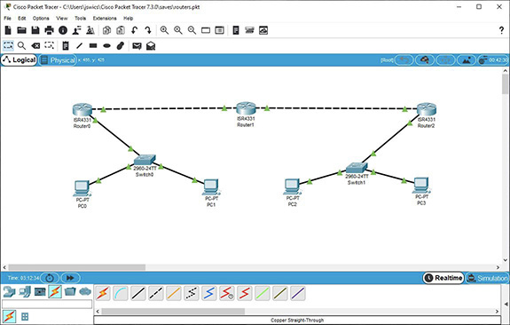
FIGURE 9-3 Modified topology for this lab exercise
a. Click the Network Devices icon (under the time counter in the lower left). In the row below that, click the Routers icon (first from the left).
b. Drag three 4331 routers (first icon on the left in the bottom-middle pane) to the topology. Put them at the top from left to right, with Router0 above Switch0, Router1 in the middle, and Router2 above Switch1.
c. Connect the three routers with two crossover cables. With the first crossover cable, for Router0, select GigabitEthernet0/0/0, and for the other side of the cable going into Router 1, select GigabitEthernet0/0/1. With the second crossover cable, for Router1, select GigabitEthernet0/0/0, and for the other side of the cable going into Router2, select GigabitEthernet0/0/1.
d. Connect each edge router to its corresponding switch with a straight-through cable. On Router0 connect a cable to GigabitEthernet0/0/1, and on Switch0 connect the other end of the cable to GigabitEthernet0/1. On Router2 connect a cable to GigabitEthernet0/0/0, and on Switch1 connect the other end of the cable to GigabitEthernet0/1.
e. Change the IP addresses of PC2 and PC3, which are plugged into Switch1, to 10.4.0.2 and 10.4.0.3, respectively. Keep the subnet mask as is (255.255.0.0). Click a blank area of the workspace, which will deselect PC3 if it’s still selected from the previous step. On the secondary toolbar, click the third icon from the left (it has a white X in it) and then click the cable between the switches to remove it. Press ESC to go back to the select function of the mouse.
f. The downward-facing red triangles (indicating a lack of a connection/configuration) will change shortly to upward-facing green triangles (indicating a good connection/configuration).
![]() 2g, 2i
2g, 2i
Step 2 Configure Router0 as follows:
a. Click Router0, the router closer to PC0 (10.1.0.100). It’s the one on the left.
b. Select the CLI tab.
c. Type no and press ENTER at the initial configuration dialog prompt. You’ll see a prompt of Router>.
d. Enter enable to go from user EXEC mode to Privileged EXEC mode. Enter configure terminal to go to global configuration mode.
e. Change the hostname of this router to R0 (for Router0).
f. Enter interface GigabitEthernet0/0/1 to go to interface configuration mode. The interface reference can be shortened to g0/0/1, and the command can be typed like this: interface g0/0/1. Notice that the # changed to (config-if)#. In this mode, you configure settings like an IP address and subnet mask for interfaces.
g. Enter ip address 10.1.0.99 255.255.0.0 to assign an IP address and subnet mask to this interface. Enter no shutdown to bring the interface up from its default shutdown state.
After a few seconds, you’ll see two green upward-facing triangles (the switch side will show an orange circle first) on the cable connecting the router to the switch, indicating a live connection between the devices.
You’ll see the following console messages, as well:
%LINK-5-CHANGED: Interface GigabitEthernet0/0/1, changed state to up
%LINEPROTO-5-UPDOWN: Line protocol on Interface GigabitEthernet0/0/1,
changed state to up
h. Enter interface g0/0/0 to configure the other interface on Router0.
i. Enter ip address 10.2.0.98 255.255.0.0 to assign an IP address and subnet mask to this interface.
j. Enter no shutdown to bring the interface up from its default shutdown state.
![]() 3a–3k
3a–3k
Step 3 Configure Router1 and Router2 as follows:
a. On Router1 (the middle router), assign a hostname of R1 (for Router1) then configure GigabitEthernet0/0/1 with an IP address of 10.2.0.99 and a subnet mask of 255.255.0.0, and GigabitEthernet0/0/0 with an IP address of 10.3.0.98 and a subnet mask of 255.255.0.0. Issue the no shut (short for no shutdown) command for each interface. If you mouse over the red or green arrows (after clicking a blank area on the main pane), you’ll see a screen tip for the interfaces that the cable is connecting to. If you mouse over the routers, you’ll see configuration information, including IP addresses.
b. On Router2 (the router on the right), assign a hostname of R2 (for Router2) and then configure GigabitEthernet0/0/1 with an IP address of 10.3.0.99 and a subnet mask of 255.255.0.0, and GigabitEthernet0/0/0 with an IP address of 10.4.0.99 and a subnet mask of 255.255.0.0. Issue the no shut command for each interface. You should only see upward-facing green arrows, indicating active connections between all devices.
c. Click each PC, the Config tab, and Settings under GLOBAL. Give each PC a gateway IP address. For PC0 and PC1, it will be 10.1.0.99, the IP address of GigabitEthernet0/0/1 of Router0. For PC2 and PC3, it will be 10.4.0.99, the IP address of GigabitEthernet0/0/0 of Router2.
d. Make sure each PC can ping its gateway.
e. Now, our entire topology is live and connected! However, at this point, the routing tables on the routers are incomplete. Each router only knows about its directly connected networks. In privileged EXEC mode in each router, type show ip route to see each router’s routing table. Table 9-1 shows the initial routing tables. Router0 only knows about the 10.1.0.0/16 and 10.2.0.0/16 networks. Router1 only knows about the 10.2.0.0/16 and 10.3.0.0/16 networks. Router2 only knows about the 10.3.0.0/16 and 10.4.0.0/16 networks. The C in the routing table means that the network is directly connected. Each routing table also has an L for a local route for each router interface’s IP address.
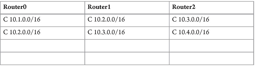
TABLE 9-1 Routing Tables, Version 1
f. Try sending a ping from PC0 (10.1.0.100) to PC3 (10.4.0.3). It will fail at Router0, as you’ll see the following output:
Reply from 10.1.0.99: Destination host unreachable.
That’s a reply from the router, not the device being pinged. Router0 will look in its routing table and will not find the destination network, 10.4.0.0/16, listed. Therefore, it will send an ICMP error message back to the host saying it can’t get there.
In global configuration mode on R0, enter the following commands:
ip route 10.3.0.0 255.255.0.0 10.2.0.99
ip route 10.4.0.0 255.255.0.0 10.2.0.99
Then go to privileged EXEC mode and display the routing table with the show ip route command.
You’ll see two new entries:
S 10.3.0.0/16 [1/0] via 10.2.0.99
S 10.4.0.0/16 [1/0] via 10.2.0.99
Static (S) routes appear for both the 10.3.0.0/16 and 10.4.0.0/16 networks, instructing the router that any traffic for those destination networks needs to be sent to 10.2.0.99, which is GigabitEthernet0/0/1 on Router 1. The next-hop IP address must be 10.2.0.99 for both of these destination networks. It can’t be the outgoing interface on Router0 (10.2.0.98, GigabitEthernet0/0/0). That doesn’t provide any meaningful information. Imagine if that interface on Router0 was connected to a switch that connected to multiple routers. Which one of those routers would be the next hop? It would be ambiguous. The next hop specified in a routing table always must be an IP address of an interface on a different router to avoid ambiguity (underneath the hood, it can work if an exit interface is specified, but weird things will happen). Furthermore, the next-hop IP can’t be 10.3.0.98 (the other side of Router1), because Router0 has no interfaces on the 10.3.0.0 network. Next-hop IP addresses, therefore, must also share a common network with the outgoing router interface.
Table 9-2 shows the updated routing tables.

TABLE 9-2 Routing Tables, Version 2
If the route to a destination network can be learned from multiple ways (for example, a routing protocol like OSPF and a static configuration), which one will be used? Cisco’s administrative distance, the first number inside the brackets, ranks the sources: 0 is for directly connected (but not shown in the routing table), 1 is for statically configured, and other values represent the various routing protocols. The lower the number, the more preferred that source of the route is.
In the square brackets, the 1 (before the slash) is the administrative distance for static routes, which makes it more preferred than routes learned through routing protocols, since an engineer took the time to configure it. The 0 (after the slash) represents the metric, which for static routes is always 0. You’ll explore this value more in the next lab exercise, in relation to a dynamic routing protocol.
g. Try sending a ping from PC0 (10.1.0.100) to PC3 (10.4.0.3). It will now fail at Router1, since Router1 doesn’t know about either the destination network (10.4.0.0/16) or the source network (10.1.0.0/16).
In global configuration mode on R1, enter the following commands:
ip route 10.1.0.0 255.255.0.0 10.2.0.98
ip route 10.4.0.0 255.255.0.0 10.3.0.99
Then, go to privileged EXEC mode and display the routing table with the show ip route command. You’ll see two new entries:
S 10.1.0.0/16 [1/0] via 10.2.0.98
S 10.4.0.0/16 [1/0] via 10.3.0.99
Table 9-3 shows the updated routing tables.

TABLE 9-3 Routing Tables, Version 3
h. Try sending a ping from PC0 (10.1.0.100) to PC3 (10.4.0.3). It will now actually reach 10.4.0.3! However, when PC3 (10.4.0.3) tries to send a reply back, the reply will be sent to PC3’s gateway (GigabitEthernet0/0/0 on Router2). Router2 does not know of the destination network in the reply (10.1.0.0/16), so the ping from PC0 (10.1.0.100) shows up as a failure from PC0’s perspective, even though the ICMP echo request reached PC3 (10.4.0.3).
If you asked me how to get from Staten Island to Rochester, I’d give you the directions, including all roads and highways. You wouldn’t feel the need to ask me how to get back, because it would be the same roads and highways, just on the other side in the opposite direction! Routing doesn’t work like that. Just because a packet can make it from PC0 (10.1.0.100) to PC3 (10.4.0.3) through three routers, this does not imply that a return packet from PC3 (10.4.0.3) to PC0 (10.1.0.100) can make it back along that same path, just in the opposite direction.
i. To allow full routing to work properly, the last route you’ll configure will be a special type of static route: a default static route.
In global configuration mode on R2, enter the following command:
ip route 0.0.0.0 0.0.0.0 10.3.0.98
Any destination network with any subnet mask, not listed in the routing table, is sent to 10.3.0.98 (GigabitEthernet0/0/0 on Router1).
Table 9-4 shows the final updates to the routing tables.
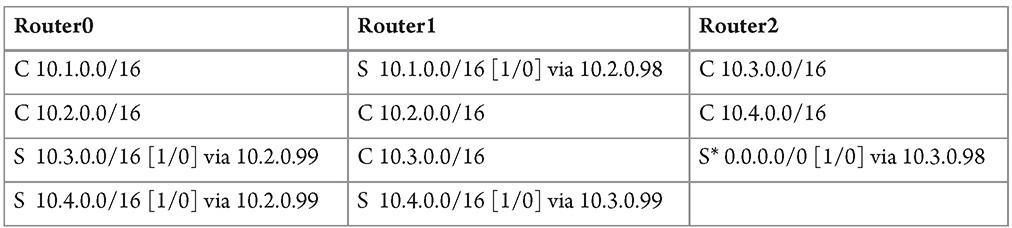
TABLE 9-4 Routing Tables, Version 4
Be careful with default static routes, because two routers that are configured with default static routes that point at each other could be sending a packet between them like a game of ping pong, until the TTL (time to live) in the packet is decremented to zero, for any destination network that neither one of them knows about!
![]() Note
Note
Default static routes (which can be redistributed dynamically) are usually configured on internal routers for packets bound for external networks. These routes take packets up a router hierarchy, with each router sending packets to the router directly above it, until reaching the edge routers. The edge routers will either have static routes to send packets directly to an ISP or will use BGP to determine the next hop to send the packets to.
j. From PC0 (10.1.0.100), send a ping to PC3 (10.4.0.3), which should now be successful!
k. To really appreciate what you just did, from the command prompt on PC0 (10.1.0.100), execute the tracert 10.4.0.3 command, which will trace the route, including all router interfaces to the destination, PC3.
![]() 4a–4h
4a–4h
Step 4 Static routing is great for stub networks, which are networks that have only one way in and one way out. There’s no need to configure a dynamic routing protocol, which will consume bandwidth and processing and bring you no additional benefits.
If there are multiple paths to get to a destination network, configuring a static route limits you. Dynamic routing protocols allow load balancing, where two or more paths of equal metrics can be used in a load-balancing fashion. Dynamic routing protocols also allow for the “recalculating” our GPSs tell us from time to time to avoid traffic or construction, in the event that a link goes down, thus providing fault tolerance. Also, if there are many routers in your topology, it’s tedious and error-prone to manually configure many static routes.
You’re going to continue using the established topology and configure the OSPF (Open Shortest Path First) routing protocol to replace the static routes, although this is still a linear topology consisting of stub networks.
a. On Router0, from global configuration mode, remove the static routes with the following commands:
no ip route 10.3.0.0 255.255.0.0
no ip route 10.4.0.0 255.255.0.0
b. On Router1, from global configuration mode, remove the static routes with the following commands:
no ip route 10.1.0.0 255.255.0.0
no ip route 10.4.0.0 255.255.0.0
c. On Router2, from global configuration mode, remove the default static route with the following command:
no ip route 0.0.0.0 0.0.0.0
![]() Note
Note
Perform the following steps on all routers.
d. Enter router ospf 1 to enable the OSPF routing protocol with a process ID of 1.
e. Enter network 10.0.0.0 0.255.255.255 area 0 to enable OSPF on all interfaces that have a first octet of 10, regardless of the last three octets.
A wildcard mask is used after 10.0.0.0 to instruct the router that we only care about the first octet matching the pattern of 10 (with 0 in the wildcard mask at the corresponding position) and that we don’t care about the other three octets (with 255 in the wildcard mask at those corresponding positions).
Although OSPF domains can be subdivided into different areas, there must be an area 0 that all routers must be a part of (with the exception of virtual links).
f. Enter END to go back down to privileged EXEC mode. After a few seconds, you’ll notice a message like this:
02:41:44: %OSPF-5-ADJCHG: Process 1, Nbr 10.3.0.98 on GigabitEthernet0/0/0 from
LOADING to FULL, Loading Done
Enter show ip route on each router, and notice that OSPF has converged. Now each router has informed the others about the network each was missing knowledge about (O stands for OSPF). In the square brackets, 110 (before the slash) refers to the administrative distance of OSPF, and the number after the slash represents the metric. Gigabit Ethernet interfaces have a metric of 1, so the number after the slash also represents how many interfaces the packet is passing through to its destination, since all interfaces in this topology are Gigabit Ethernet interfaces.
g. From each PC, ping the other three PCs. You should have full connectivity on all devices at this point.
h. From PC0, run tracert 10.4.0.3 and notice paths the packets are taking from one PC to the other.
![]() 30 MINUTES
30 MINUTES
Lab Exercise 9.03: Passwords and SSH
Both the routers and switches you’ve configured in this chapter have several passwords that can be used to provide a measure of security. SSH (Secure Shell) can be used to remotely configure routers and switches while still maintaining confidentiality, as encryption is protecting the confidentiality of the communications with SSH.
Learning Objectives
In this lab exercise, you’ll implement a level of security to the routers and switches. At the end of this lab exercise, you’ll be able to
• Configure and use multiple router and switch passwords
• Configure and use SSH to remotely access routers and switches
Lab Materials and Setup
The materials you need for this lab are
• The Principles of Computer Security: CompTIA Security+ and Beyond textbook
• A web browser with an Internet connection
• One or more Cisco Ethernet switches with at least two PCs (optional)
Let’s Do This!
By default, there are no passwords on routers or switches. That, of course, is something that needs to be corrected before deploying these devices into production networks. Routers and switches can have passwords that are shared between all users or that are tied to individual usernames. Passwords can be set on the console line, SSH lines, and for privileged EXEC mode. Now, you’ll explore all of these options. Pick any device in the current topology, as the following commands and instructions work the same on routers and switches.
![]() Note
Note
Press ENTER after every command.
![]() 1a–1c
1a–1c
Step 1 Configure and use an enable secret, as follows:
a. From user EXEC mode, type enable to go to privileged EXEC mode. Then type configure terminal to go to global configuration mode.
b. Enter the following command to configure the enable secret, a password that will need to be entered to move from user EXEC mode to privileged EXEC mode (also referred to as enable mode) after entering the enable command. This enable secret will be stored as a hash in the running configuration file.
enable secret bob
c. Type END to go down to privileged EXEC mode and then disable to go down to user EXEC mode. Type enable and notice the Password: prompt. Type the password of bob to enter privileged EXEC mode.
![]() 2a–2d
2a–2d
Step 2 Configure and use a console password, as follows:
a. Type configure terminal to go to global configuration mode.
b. Enter the following commands. The first moves you into line configuration mode for the console, the second sets the console password to alice, and the third specifies that a simple password (the one configured in the previous command), shared by all users, will be used as a login password for anyone.
line con 0
password alice
login
c. Type END to move back down to privileged EXEC mode and then exit to leave the switch altogether.
d. Press ENTER to log in. You’ll now notice the Password: prompt. Enter the password of alice to log in through the console.
![]() 3a–3d
3a–3d
Step 3 Configure and use a username and password, as follows:
a. Type enable and provide the enable secret to enter privileged EXEC mode. Type configure terminal to enter global configuration mode. Enter the following commands. The first configures a username of jonathan with a password of weissman. The second moves you into line configuration mode for the console. The third specifies that instead of a shared password for everyone, a username/password combination stored on the local switch will be checked. The fourth removes the shared password, configured earlier. The last step is optional, because with login local specified, the simple password will not be used. However, it’s good practice to remove it from the configuration file so there’s no confusion.
username jonathan password weissman
line con 0
login local
no password
b. Type END to move back down to privileged EXEC mode and then exit to leave the switch altogether.
c. Press ENTER to log in. You’ll now notice the Username: prompt. Enter jonathan. You’ll now notice the Password: prompt. Enter weissman to log in through the console.
![]() 4b–4j
4b–4j
Step 4 Even though switches are Layer 2 devices, and individual switchports aren’t configured with IP addresses (although each has its own MAC address), the switch itself can be configured with an IP address (Layer 3) for SSH (Secure Shell) access, SNMP (Simple Network Management Protocol) access, and more. An IP address is assigned to a switch’s switched virtual interface (SVI), also known as a virtual local area network (VLAN) interface.
For this activity, you’ll use Switch0. On the switch, you’ll configure an SVI. Then you’ll configure and use SSH between a PC and the switch.
a. Type enable and provide the enable secret to enter privileged EXEC mode. Type configure terminal to enter global configuration mode. Enter the following commands. The first changes to Vlan 1 interface configuration mode. The second assigns an IP address of 10.1.0.52 and a subnet mask of 255.255.0.0 to the Vlan 1 interface. There could be multiple Vlan interfaces enabled on a switch, but by default all ports are assigned to Vlan 1. You must have a Vlan interface enabled, with a device connected to it, for an SVI to come up and be usable. The third changes the default state of shutdown of this interface to no shutdown, or on. The fourth exits down to global configuration mode. The fifth assigns a default gateway to this switch for remote communication.
interface vlan 1
ip address 10.1.0.52 255.255.0.0
no shutdown
exit
ip default-gateway 10.1.0.99
b. Remote access should never be used with an old, obsolete protocol named Telnet, since it passes all information, including passwords, in plaintext in both directions. SSH, on the other hand, encrypts traffic in both directions, and is what you’re going to set up next.
From global configuration mode, enter the following commands. To create the encryption keys (public key and private key), the fully qualified domain name (FQDN) of the switch is used. The FQDN includes the hostname, (previously configured but repeated here for completeness purposes), as well as the domain name, configured now. The third command generates the keys with a mod of 2048. The fourth command restricts the SSH version to 2, prohibiting the weaker version 1.
The fifth command moves you into line vty (virtual teletype, used for SSH connections) mode. The sixth command specifies that for the 16 (0-15) concurrent SSH lines, the username/password pair should come from the local switch’s database. The seventh command specifies that only SSH, and not Telnet, can be used on the vty lines on this switch.
hostname S0
ip domain-name weissman.edu
crypto key generate rsa
When prompted with How many bits in the modulus [512]:, type 2048 and press ENTER.
ip ssh version 2
line vty 0 15
login local
transport input ssh
c. Click any PC in the topology. Select the Desktop tab and click the Telnet / SSH Client icon (toward the bottom). Verify that Connection Type is set to SSH. In the Host Name Or (IP address) box, enter 10.1.0.52 (the IP address of the switch you enabled for SSH). In the Username box, enter jonathan. Click the Connect button.
d. When prompted for the password, enter weissman.
e. Type in enable and enter the enable secret at the Password: prompt.
Voilà! You’ve successfully logged in to the switch through a remote connection using SSH.
Remember from Chapter 5 how TLS uses the Diffie-Hellman key exchange? SSH uses it the same way.
The SSH client on the PC and the SSH server on the switch agree on a shared secret with the Diffie-Hellman key exchange. This shared secret is the symmetric key that encrypts communications in both directions, including the username and password that the client sends to the server for authentication. The SSH server’s (here, the switch is the SSH server) public key is transmitted to the client the first time the client connects to that server. Just like with TLS, during the DHKE, the SSH server hashes values and encrypts that hash with its private key, forming a digital signature. The client decrypts the encrypted hash with the server’s public key and computes the hash on its own. If the computed hash matches the decrypted hash, the client can trust that the server really is the server and that the symmetric key (shared secret) is legitimate.
Instead of a password, a more secure method for client authentication involves a public/private key pair. The client can generate a public/private key pair and place its public key on the server. The server would then encrypt a random number with that public key and send the ciphertext to the client. If the client has the corresponding private key, it will decrypt the message. The decrypted message and the session key (the shared symmetric key that is established with DHKE before this phase) will then be hashed and sent to the server in response. The server uses the original number and the same session key to compute the hash value itself. If the computed hash matches the received hash, the client is authenticated. This provides greater security than a simple username/password pair that can be stolen and used by an attacker. Furthermore, SSH keys can be thousands of bits long, making them a lot harder to crack, compared to passwords that consist of around 12 characters or so. Other advantages include that a private key isn’t sent to the server the way a password is, the SSH connection can only originate from the machine that has the private key, and you can even add a password to your SSH key authentication for further security. The convenience of passwords shouldn’t outweigh the security of keys. However, when SSH is used with routers, it’s very common to see the password authentication method in place.
f. Type show running-config to see the running configuration file. Find all of the items you configured. Advance line by line with the ENTER key and page by page with the SPACEBAR. CTRL+C will break out of the output.
g. Type copy running-config startup-config to save the running configuration file in RAM as the startup configuration file in NVRAM. At the Destination filename [startup-config]? prompt, press ENTER to accept the default and correct name of this file, shown in square brackets. You’ll see [OK], indicating that the command worked.
The next time the switch boots up, the startup configuration file from NVRAM will be copied into RAM as the running configuration file. This command and process works the same way on routers, too.
h. Type show ip ssh to see status information about the switch’s SSH setup.
i. Type show ssh to see information about current SSH sessions, which will be the one you’re currently using.
j. Now, on one of the routers, enable SSH (an enable secret must be set for this to work, as well) and use a PC to SSH into it. You can SSH into one of the already configured interface IP addresses.
Lab Analysis
1. Do switch interfaces have MAC addresses?
![]()
2. Do switch interfaces have IP addresses?
![]()
3. Why would static routing be chosen over dynamic routing?
![]()
4. Why would dynamic routing be chosen over static routing?
![]()
5. How many types of passwords can be configured on routers and switches?
![]()
Key Term Quiz
Use the terms from the list to complete the sentences that follow:
hashed
next hop
routing table
SAT
SSH
1. The switch uses its ____________ to determine which interfaces to send traffic out of.
2. When configuring static routes, you need to specify the ____________ address, which is where the packet should be sent to next.
3. Connecting remotely to a router or switch can be done with ____________ instead of using a console connection.
4. The enable secret is stored in ____________ format.
5. Letters like C and S appear in the ____________.