
Chapter 14
Top-Down Design with Use Case, Activity, Sequence, Component, and Class Diagrams
What's in this chapter?
- Creating and using use case and activity diagrams
- Creating and using sequence and component diagrams
- Generating code from a class diagram
Wrox.com Code Download for this Chapter
The wrox.com code downloads for this chapter are found at www.wrox.com/remtitle.cgi?isbn=1118314081 on the Download Code tab. The files are in the Chapter 14 download folder and individually named as shown throughout this chapter.
Chapter 13 introduced you to architecture and modeling in the software space, and hinted at all the architectural goodness available in Visual Studio Ultimate 2012. This chapter dives deeper into several aspects of that, looking at use case, activity, sequence, component, and class diagrams.
One advantage of modeling tools is that they enable you to design the architecture of the application. Part of that design process is defining common terms around the problem domain, and then ensuring that everyone on the team understands those concepts. Using the use case, activity, and sequence diagrams, you can model your application, while ensuring that everyone on the team understands exactly what is being built.
This chapter is divided into five main sections:
- Use Case Diagrams
- Activity Diagrams
- Sequence Diagrams
- Component Diagrams
- Class Diagrams
Each section begins with a walkthrough of how to build a diagram, as well as a diagram explanation. After that, the discussion looks at all the objects available when building a particular diagram.
Use Case Diagrams
A use case diagram provides a graphical overview of the functionality of a system. It shows who is using the system and what they can do with it.
A use case diagram does not show details of use cases themselves; instead it provides a summary view of use cases, actors, and systems. Details (such as the order in which steps must be performed to accomplish the use case) can be described in other diagrams and documents, and then linked to the related use case. Use cases (and, by extension, use case diagrams) deal only with the functional requirements of a system. The architecture and any internal details are described elsewhere.
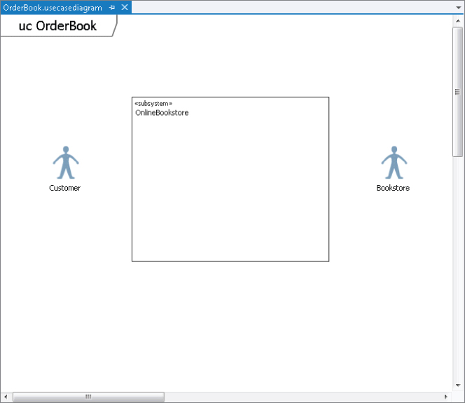
Creating a Use Case Diagram
The following steps walk you through the process of creating a use case diagram. You are going to create a use case diagram of a customer interacting with an online bookstore system. The customer should be able to view the books offered and order a book. The bookstore should be able to update the list of available books, as well as deliver ordered books to the customer.
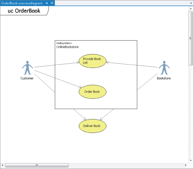
Although Figure 14.2 is a very simple use case diagram, it is still very informative. You can also have more-complex use case diagrams, with multiple subsystems, actors, and use cases. A best practice would be to start off describing the system with a few major use case diagrams. Each of those diagrams should define a major goal of the system. After those goals have been defined, use some of the other objects from the use case diagram toolbox to define the system in more detail.
Let's break the Order Book use case down in more detail. Figure 14.3 shows a use case diagram that does this by using the Include relationship.
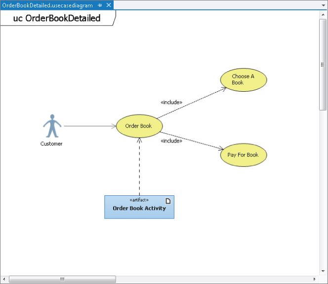
The Include relationship shows that a use case uses all the behavior of the included use case. To differentiate it from a regular association, the Include relationship is represented as a dotted line with an arrow on the end (per the UML 2.1.2 specification, available at http://aka.ms/UML212). The arrow should always point to the more detailed use case. The Include relationship is also labeled with the keyword <<include>>. Each of the included use cases is a step that the actor may have to take in order to complete the main use case. In this example, in order for the customer to order a book at the online bookstore, the customer must choose a book and then pay for the book.
A use case diagram does not specify in what order the particular use cases should happen, or when a particular use case is necessary. To make that information clear, attach an Artifact object to the general use case by dropping an Artifact object onto the use case diagram and then dragging a Dependency relationship between the Artifact element and the general use case. An Artifact element enables you to attach a separate document to the use case (for example, a text file that describes the steps to take) or reference another diagram.
Use Case Diagram Toolbox
Figure 14.4 shows the different elements and associations available for use case diagrams.
Table 14.1 describes the different elements and associations.
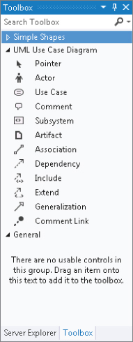
Table 14.1 Use Case Diagram Toolbox Objects
| Name | Description |
| Pointer | Turns the mouse back into a regular mouse pointer |
| Actor | Adds a user or external system that interacts with a system |
| Use Case | Adds a specification of actions that are performed in pursuit of a specific goal |
| Comment | Adds a comment for more details |
| Subsystem | Adds a system component. Place the use cases inside the subsystems that support it |
| Artifact | Adds a reference to a diagram or document |
| Association | Links an actor with a use case |
| Dependency | Specifies that the definition of one element depends on the definition of another |
| Include | Specifies that one use case invokes another use case |
| Extend | Specifies that one use case extends the definition of another in specific conditions |
| Generalization | Specifies that one element is a specialized version of another, inheriting its features and constraints |
| Comment Link | Connects a comment to a diagram element |
Activity Diagrams
An activity diagram is used to show a business or software process as a workflow through a series of actions. These actions could be performed by any number of objects, including people, software, or computers. Activity diagrams can be used to model the logic captured in a particular use case or to model detailed business logic. One easy way to think of activity diagrams is to think of them as a flow chart.
An activity diagram always has a starting node, a series of activities, and a final node that indicates the end of the activity.
Creating an Activity Diagram
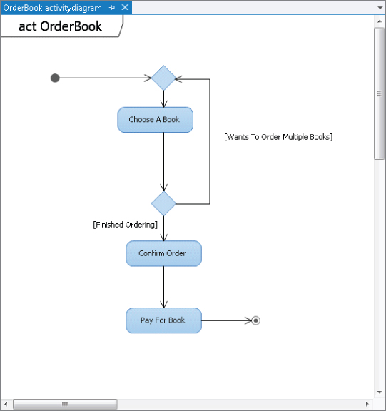
The following steps outline the process of creating an activity diagram that shows the sequence of activities for ordering a book from the online book store. A customer first chooses a book to order. After a book is chosen, the customer makes a decision whether to order more books or confirm the order. After the customer is finished selecting books, the customer confirms the book order and then pays for the order.
Next, you must add the connectors to show the flow of activity through this activity diagram. Double-click the Connector element to select it. On the activity diagram, drag a line between the Initial Node element and the Merge Node. Continue connecting the other elements on the diagram as follows:
When finished, the diagram should appear similar to Figure 14.5.
Concurrent Flow in an Activity Diagram
Activity diagrams can also be used to describe a sequence of actions that execute at the same time. This sequence of actions is known as a concurrent flow. Figure 14.6 shows an example of a concurrent flow activity diagram related to ordering a book online.
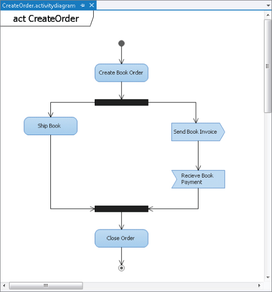
At the start of this activity diagram, an order is created. After an order is created, two different branch processes are started. The black bar that the Create Book Order action leads into is called a Fork Node, and is used to divide a single flow into concurrent flows. In this case, one flow leads to the Ship Book action. The other leads to the Send Book Invoice element.
The Send Book Invoice element is not a regular action element. It is a Send Signal Action element. This indicates an action that sends a message to another activity for something to happen. The Receive Book Payment is an Accept Event Action element. It is an action that waits for a message before the flow can continue. In the case of Figure 14.6, a book invoice will be sent, potentially to a payment system. The flow in the activity diagram waits until a response is received back, indicating that the book has been paid for. Both the Ship Book and the Receive Book Payment actions are then merged back into a single process using a Join Node. The activity ends with the closing of the order.
Activity Diagram Toolbox
Figure 14.7 shows the different elements and associations available for activity diagrams.
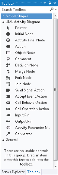
Table 14.2 describes the different elements and associations.
Table 14.2 Activity Diagram Toolbox Objects
| Name | Description |
| Pointer | Turns the mouse back into a regular mouse pointer |
| Initial Node | Adds the start of the activity |
| Activity Final Node | Adds an end to the activity |
| Action | Adds a single step that occurs in the activity |
| Object Node | Adds a node that can transmit, buffer, filter, and transform objects |
| Comment | Adds a comment for more details |
| Decision Node | Divides a single incoming flow into a choice between alternate outgoing flows |
| Merge Node | Combines incoming alternate flows into a single outgoing flow |
| Fork Node | Divides a single incoming flow into concurrent outgoing flows |
| Join Node | Combines incoming concurrent flows into a single outgoing flow |
| Send Signal Action | Adds an action that sends a signal to another system or activity |
| Accept Event Action | Adds an action that waits for a signal or event |
| Call Behavior Action | An action that is defined in more detail on another activity diagram |
| Call Operation Action | An action that calls an operation on an instance of a class |
| Input Pin | Represents data that an action requires. It allows data to flow into an action |
| Output Pin | Represents data that an action produces. It allows data to flow out of an action |
| Activity Parameter Node | Creates a parameter that conveys data into or out of the activity |
| Connector | Adds a connection or flow between elements on the diagram |
Adding an Activity Diagram to a Use Case Diagram
Earlier in this chapter when creating use case diagrams, you saw an Artifact element attached to a use case (see Figure 14.3). One available option with Artifact elements is the capability to associate them with an activity diagram (and, as an extension, any physical document).
To do this, drag an Artifact element onto the OrderBook.usecasediagram you created earlier in this chapter. In the properties window for the Artifact element, select the Hyperlink property. This will open the Open File dialog box, allowing you to select a diagram, document, or other file to associate with the Artifact element on the use case diagram.
Sequence Diagrams
A sequence diagram is used to show the sequence of interactions between classes, components, subsystems, or actors. A sequence diagram is read from top to bottom, indicating the flow of time through the system. From left to right, the diagram itself shows the flow of control from one element to the next.
Creating a Sequence Diagram
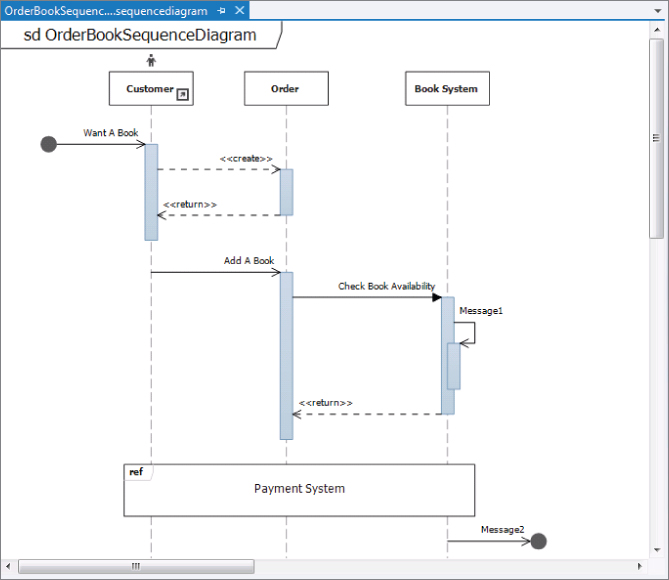
The following steps walk you through creating a sequence diagram that shows the sequence of flow for ordering a book from the online bookstore. A customer first has the desire to purchase a book. At that point, the customer adds a book to a shopping cart. The order system checks the availability of the book and performs some internal processing. The availability of the book is returned to the ordering system. The payment system is represented by a separate sequence diagram, so a reference placeholder is inserted into this diagram. Finally, a message is sent to an unknown (or unspecified) system at the end of the process.
Sequence Diagram Toolbox
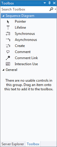
Figure 14.9 shows a screenshot of the different elements available for sequence diagrams.
Table 14.3 describes the different elements and associations.
Table 14.3 Sequence Diagram Toolbox Objects
| Name | Description |
| Pointer | Turns the mouse back into a regular mouse pointer |
| Lifeline | Adds a participant (such as a class or object) to an interaction sequence |
| Synchronous | Adds a message that calls an operation and expects a response |
| Asynchronous | Adds a message that calls an operation but does not expect a response |
| Create | Adds a message that calls an operation that creates an instance of the target |
| Comment | Adds a comment for more details |
| Comment Link | Connects a comment to a diagram element |
| Interaction Use | Adds an interaction use to create a reusable sequence or to reference another sequence |
Component Diagrams
A sequence diagram enables you to model and visualize the messages of a system. With the component diagram, you can visualize the components of the system that implement the system functionality, as well as other puzzle pieces of the system (such as web services, user interfaces, COM components, and so on). A component diagram depicts the relationships between various components of your application or system.
A component diagram shows the parts of a design for a software system. These components could be executables, DLLs, or even entire systems. At this level, you aren't necessarily trying to decide exactly how things are being built. Rather, you are just trying to break down the architecture into something more manageable and understandable. You can use a component diagram to visualize the high-level structure of the system and the service behavior that the components both provide and consume.
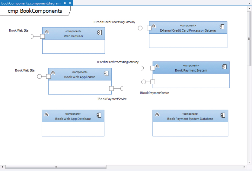
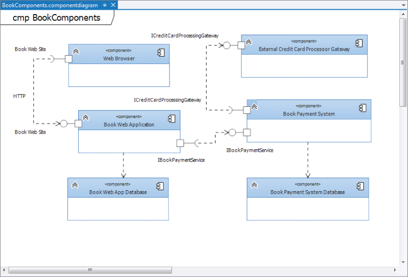
Think of a component as a modular unit that is replaceable. You don't know how the internals of the component work. Instead, you know what interfaces a component provides or consumes. Components on a component diagram have interfaces, either required interfaces or provided interfaces. An interface can be anything, from a website to a web service. A required interface indicates functionality that a component expects to consume. A provided interface indicates functionality that a component provides for other components to consume. Each required interface on a component diagram should be linked to a provided interface.
Creating component diagrams has a couple of nice benefits. It can help the development team understand an existing design and see potential ways to improve it. More importantly, thinking of the system as a collection of components with well-defined interfaces improves the separation between components, which can make the design easier to change as the requirements change.
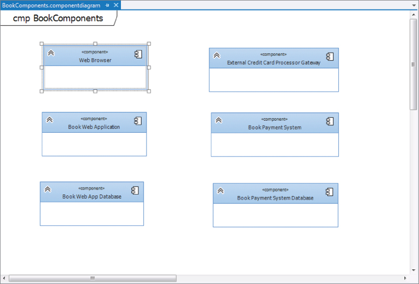
Creating a Component Diagram
Use the following steps to create a component diagram that represents the different components of the online bookstore system. The different components include a web browser, the bookstore website (both the web application and the backend database), the bookstore payment system, and a way to process credit cards.
- Using the toolbox, click the Component element, then click a blank area of the diagram. An empty Component element appears on the diagram. This is useful for creating new components.
- Existing components from other diagrams in the same modeling project can also be added to the diagram. Either open the existing diagram or open the UML Model Explorer window (by selecting View⇒Other Windows⇒UML Model Explorer). Right-click the component to add to the component diagram and then select Copy. Right-click a blank area of the component diagram and select Paste Reference to create a copy of the component on the new diagram.
- Book Web Application
- Book Web App Database
- External Credit Card Processor Gateway
- Book Payment System
- Book Payment System Database
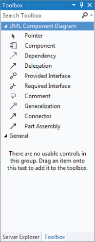
Component Diagram Toolbox
Figure 14.13 shows the different elements and associations available for component diagrams.
Table 14.4 describes the different elements and associations.
Table 14.4 Component Diagram Toolbox Objects
| Name | Description |
| Pointer | Turns the mouse back into a regular mouse pointer |
| Component | Adds a component that defines a reusable unit of system functionality |
| Dependency | Defines how an element depends on another element. Begin the relationship from the dependent element |
| Delegation | Designates behavior between a port on an outer component and an interface on an inner component |
| Provided Interface | Adds an interface that a component provides to other components |
| Required Interface | Adds an interface that a component requires from other components |
| Comment | Adds a comment for more details |
| Generalization | Defines how a component derives from another component. Begin the relationship from the derived component |
| Connector | Creates a default relationship between shapes based on the types of shapes being connected |
| Part Assembly | Specifies a connection between parts in a component. Connects a required interface on one part to a provided interface on another part |
Class Diagrams
Class diagrams depict the classes within an application or system and the relationship that exists between them. Different symbols represent the varying relationships that may exist (such as inheritance or association). This information is described independent of any reference to a particular implementation of the class. The purpose of the class diagram is to focus on the logical aspects of the classes instead of how they are implemented.
In a class diagram, a type is a class, interface, or enumeration. Class and interface objects can have attributes defined. An attribute is a value that can be attached to an instance of a class or an interface. Classes and interfaces can also have operations defined. An operation is a method or function that can be performed by an instance of a class or interface.
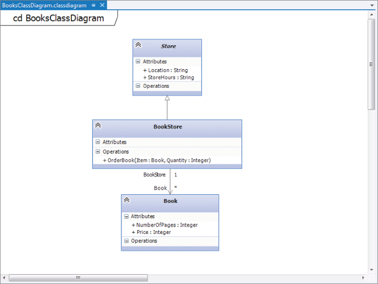
On a class diagram, you can draw associations between any pairs of types. An association indicates that the system being developed stores links between the instances of the associated types. An association is a diagrammatic method of showing an attribute or pair of attributes. For example, if you have a class BookStore that has an attribute of type Book, you can state that definition by drawing an association between Bookstore and Book.
Using the Model Explorer, you can locate interfaces you have defined on the component diagram and drag those directly onto the class diagram to create them.
Creating a Class Diagram
Use the following steps to create a class diagram that shows the relationship between a Store class, a BookStore class, and a Books class. A bookstore is a more specific version of a store, and a bookstore contains multiple books.
Figure 14.14 shows the final result of the class diagram.
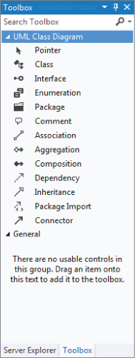
Class Diagram Toolbox
Figure 14.15 shows the different elements and associations available for class diagrams.
Table 14.5 describes the different elements and associations.
Table 14.5 Class Diagram Toolbox Objects
| Name | Description |
| Pointer | Turns the mouse back into a regular mouse pointer |
| Class | Adds a type that defines a class |
| Interface | Adds an interface to specify the attributes and operations that classes require to realize this interface |
| Enumeration | Adds a type that defines a list of specific values |
| Package | Adds a package to organize types according to their namespaces |
| Comment | Adds a comment for more details |
| Association | Defines how an element interacts with another element. Begin the relationship from the referencing type |
| Aggregation | Specifies that the source type refers to parts of the target type. The parts can be shared with another owner |
| Composition | Specifies that the source type has parts of the target type. The parts cannot be shared with another owner |
| Dependency | Defines how a type depends on another type. Begin the relationship from the dependent type |
| Inheritance | Defines how a type inherits or realizes the members of another type |
| Package Import | Defines how a package imports types defined in another package. Begin the relationship from the package that uses another package |
| Connector | This connection tool creates a default relationship between shapes, based on the types of shape being connected |
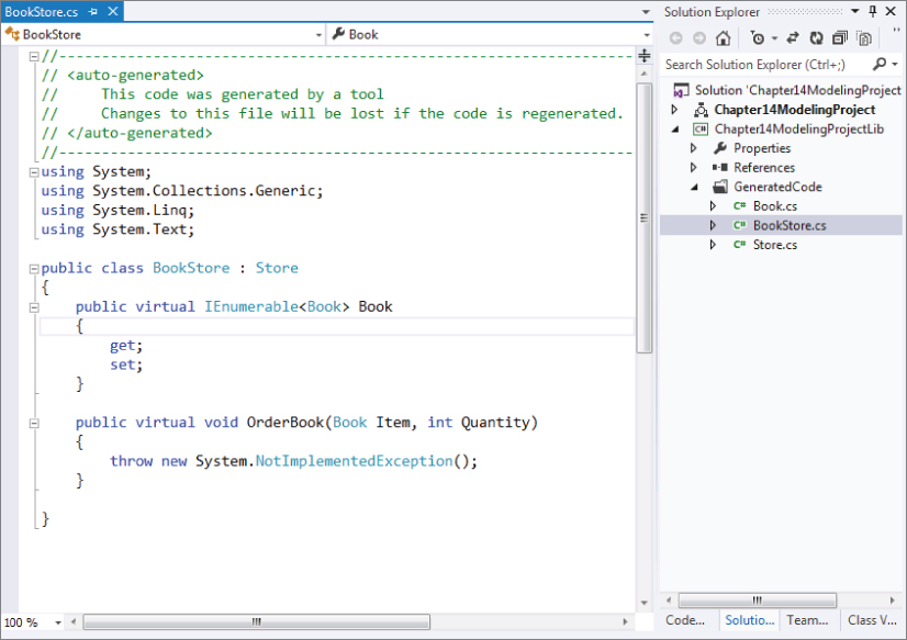
Generating Code from a UML Class Diagram
Visual Studio 2012 includes a new feature: the ability to generate code from a UML class diagram. Using the class diagram as a base, you can generate skeleton code from the class diagram elements. In addition, you can also create UML class diagrams from your code base as well. This functionality wasn't available in Visual Studio 2010 unless you installed the Visual Studio 2010 Visualization and Modeling Feature Pack.
To generate code from a class diagram, right-click the class diagram and select Generate Code from the context menu. By default, executing this command generates a C# type for each type on the UML class diagram. The following are the default results for generating code:
- A C# type is produced for each type on the UML model. Each type is placed in a separate code file.
- A C# property is generated for each attribute of a UML class.
- A C# method is generated for each operation of a UML class.
- A C# field is generated for each navigable association in which the class participates.
- If the UML type is contained in a package, the generated C# type is placed inside a namespace, and the file is generated in a folder with the same name as the namespace.
However, you can customize this behavior — including the language generated as well as the different outputs — by modifying the text templates that are used for generating the code.
Figure 14.16 shows the BookStore.cs C# class that was generated by running the Generate Code command against the BooksClassDiagram.classdiagram class diagram created earlier in this section. A new class named BookStore that inherits from class Store was created. Also, a stub method for the operation OrderBook was created as well.
Summary
This chapter examined the capabilities of use case, activity, sequence, component, and class diagrams. You looked at how to create a use case diagram, and learned about its different components. Next, you learned about activity diagrams, where, in addition to examining an example of how to build a diagram, you also learned how to link an activity diagram back to a use case diagram. You then examined sequence diagrams, their components, and how to create them.
You learned the purpose behind component diagrams, how to create them, and the different elements available to component diagrams. Finally, you learned about class diagrams and how they are used. You learned about the different elements that are available for class diagrams and concluded the chapter with a look at how to generate code from a class diagram.
Chapter 15 discusses how you can use the Architecture Explorer to drill down into the existing project, which helps you to understand the different aspects of the project. The information in the Architecture Explorer can then be turned into a graphical view by creating a dependency graph.