
The previous chapter discussed remotely controlling a wheeled robot. This chapter covers using a robotic arm, which is substantially different. Although robotic arms can be attached to a mobile robot, they are usually fixed to the floor or a table, and can therefore be directly connected to the PC that controls them with no need for wireless communication or an onboard PC.
There are many different types of articulated, robots, and arms are only a small subset. For example, bipedal humanoid robots are articulated, and so are robots that emulate snakes. However, the robot arms that build cars are probably one of the first and most successful applications of robotics in industry.
Relatively cheap hobby arms are available from several sources, such as Lynxmotion. This chapter shows you how to use a Lynx 6 robotic arm to do some simple operations. The L6 is a small, lightweight arm that is intended for hobbyists and education. The software on the book's website (www.proMRDS.com or www.wrox.com) includes a Lynx6Arm service for controlling the arm, as well as some examples demonstrating how to use it. The original service software and several of the photos in this chapter are courtesy of Lynxmotion.
A Lynx arm is not suitable for industrial use. For that you need something like a heavy-duty arm from KUKA. You might be interested in trying out the KUKA Educational Framework for MRDS, available for download from www.kuka.com.
The KUKA framework contains several tutorials using a simulation of a KUKA LBR3 arm. However, the tutorials rapidly get into complex mathematics. The objective in this chapter is to provide an overview without going into the great depth of the KUKA tutorials.
If you have not read Chapter 8, it would be a good idea to go back and do so now. It introduces a lot of key concepts for articulated arms and does so using a simulation so that you don't have to worry about breaking anything if you make a mistake! This chapter assumes that you are familiar with the material in Chapter 8.
The common factor for all articulated robots is joints. Joints can take a variety of forms, with the most common type based on a servo that can rotate around a single axis. In this case, the position of the servo is referred to as the axis angle or twist around the main axis (also called the local axis).
The Joint class in MRDS describes the type of joint, how it is connected, and several other properties. Each joint has one or more values associated with it that describe the current pose of the joint. Usually, the application maintains these values itself so that it always knows the configuration of the arm. Some arms enable you to query their current position or they provide continuous feedback. This is important for ensuring that the state information in your service actually matches the real state of the arm.
There are two primary types of joints in MRDS: angular and linear. This chapter deals exclusively with angular joints because that is what the L6 arm uses.
Rotation of a servo can be changed into a linear motion using appropriate gears. For example, a gripper can be built using a servo to spread the fingers apart or squeeze them together. Figure 15-1 shows a close-up of a L6 arm gripper in which the gears and linkages are clearly visible. The gripper servo is underneath the hand and is not visible. The servo in the middle of the wrist is for rotating the wrist, whereas the one at the end of the arm (on the right-hand side of the photo) is for tilting the wrist up and down.
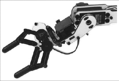
Pictures of the L6 arm are courtesy of Lynxmotion and are available from its web site (
www.lynxmotion.com).
In Chapter 8, the simulation uses two linear joints to make the gripper. This complexity is hidden from you if you connect to the simulated L6 arm using the generic contract for articulated arms.
The state of an articulated arm consists of, at a minimum, a list of joints and an end effector pose. The purpose of the joint list is obvious, but if you have never used an arm before, the term end effector might be new to you.
Most robotic arms have a gripper or some other device at the end of the arm to do useful work. This is called an end effector or sometimes a tool. The location and orientation of the end effector is the most valuable piece of information that you can have. Unfortunately, as explained in a moment, determining the position of the end effector is a complicated process.
The KUKA documentation uses two terms related to the end effector:
End of Arm (EOA): The EOA is the very extremity of the arm. In the case of the L6 arm it is the tip of the gripper fingers. As the gripper opens and closes, the linkages cause the tips of the fingers to move slightly closer or farther away from the wrist (as well as side to side). This small variation is not worth worrying about.
Tool Center Point (TCP): The TCP is the location inside the tool that is important for operating the tool. For a gripper, this is midway along the fingers, where the gripper makes contact with an object that it is supposed to pick up. If you refer to Figure 15-1 and imagine an object in the center of the gripper, you will understand the difference between EOA and TCP.
Servo motors are used in remote-controlled (R/C) toys such as cars and airplanes. Due to the large number of motors produced each year, they have become commodity items that are readily available in a range of sizes and types. There are both digital and analog servos, but the difference is not important here.
To move a servo, you send it a series of pulses 50 times per second (20 milliseconds apart), with the width of the pulses controlling the rotation angle of the servo horn. Figure 15-2 shows a servo with the corresponding pulses and rotation angles. The white disc on the servo is the horn, although servos often come with a horn shaped like a cross. Notice its orientation.
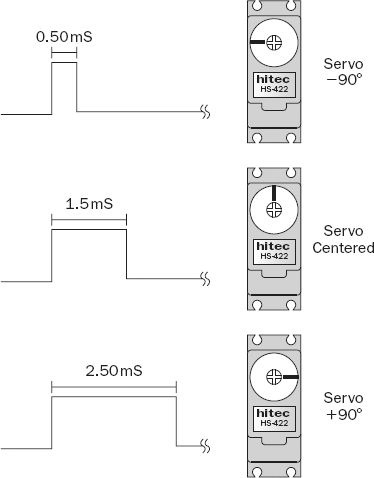
Reproduced from the SSC-32 Users Manual version 2.0 with permission from Lynxmotion.
The L6 arm has a Lynxmotion SSC-32 controller that is used to send the appropriate pulses to the servos, which means that the MRDS service does not have do to this every 20ms. The SSC-32 can handle up to 32 servos, but the arm only has 6. It interfaces to a PC using a serial port.
A servo motor continues to drive the servo horn until the correct angle is obtained. (Servos have an internal sensor, usually a potentiometer, to measure the angle.) If the servo is prevented from reaching the desired angle, it will keep pushing in the appropriate direction, effectively applying pressure, but this causes high current drain on the power supply, and there is a limited amount of torque that the servo can apply. Once the servo reaches the correct orientation, it resists external attempts to move it and effectively "locks" itself in place. However, as soon as the power is turned off, the servo will "slump" down depending on the weight of the linkages that it is holding.
Most servo motors only need to operate over a range of −45 to 145 degrees, e.g., for the control surfaces for flying a plane. However, it is quite common for servos to have a range of −90 to +90 degrees, and some might operate over −180 to +180 degrees.
Some inexpensive robots, including the Boe-Bot, use modified servo motors in which the potentiometer has been removed or disabled. Because the servo can never find its target location, it keeps driving in the same direction and, in effect, becomes a conventional electric motor.
The last point to note about servos is that when you power them up, the servo controller usually has no idea where the servos are positioned. The interface to a servo consists of only three wires: power, ground, and pulse. There is no way for them to provide feedback. As a result, as soon as you start sending pulses to the servo, it jumps from its initial position to the specified position. For an arm, this can be quite surprising and even dangerous.
Driving an arm to reach a particular position involves sending commands to the various joints. Because the joints cannot instantaneously reach their destinations, you need to employ some strategy to ensure that the servo motors are not overloaded. There are physical limits to how fast a servo can move based on the maximum torque that the motor can apply.
In general, the speed of a joint should be kept well below its physical maximum to avoid burning it out. Another speed consideration is that the arm has inertia, and if it moves too fast it will overshoot, causing it to oscillate backwards and forwards as it settles down to the final destination.
The Lynx6Arm service provided with this chapter limits the speed that joints are allowed to move because the L6 arm is a little fragile. The service does this by calculating the difference between the current joint angle and the desired joint angle, calculating the time required based on a maximum angular speed, and then instructing the SSC-32 controller to make a timed move. If a time parameter is not supplied in a command to the SSC-32, the joint jumps to its destination as fast as possible.
The following code in the Lynx6Arm service handles the SetJointTargetPose request that sets the value for a single joint. You don't need to know how it works in order to use the request, but it is interesting to understand how the service works under the hood.
The function starts by looking up the joint details and converting the joint orientation to an angle in degrees. As with many MRDS operations, there is a lot of converting to and from quaternions and axis angles when you are working with joints. You need to become familiar with these—for example, to make a SetJointTargetPose request!
private IEnumerator<ITask> SetJointPoseHandler(armproxy.SetJointTargetPose update)
{
    // Find out which joint it is from the name
    string name = update.Body.JointName;
    int index = _channelLookup[name];

    // Get the joint
    Joint j = _jointLookup[name];

    // Figure out the desired angle in degrees
    AxisAngle orientation = update.Body.TargetOrientation;
    float orientationAngle = orientation.Angle * Math.Sign(orientation.Axis.X);
    float jointAngle = Conversions.RadiansToDegrees(orientationAngle);
The time parameter is calculated based on the change in the joint angle and the MaxAngularSpeed, which is a value set in the service state. If you want to make the arm move faster, you can change the value of MaxAngularSpeed and recompile the service. (It is not exposed through a configuration file.) However, be aware that making the arm move too fast can make it wobble!
float angleDiff;
    int moveTime;

    // Calculate the difference between the current angle and the
    // requested angle and then figure out the time to take
    angleDiff = Math.Abs(jointAngle—_state.Angles[index]);
    // Calculate the elapsed time for the move
    moveTime = (int)((angleDiff / _state.MaxAngularSpeed) * 1000.0f);
    // If the time is very small, ignore it
    if (moveTime < 20)
        moveTime = −1;
The jointAngle is saved in a cache in the state for use the next time. It must be converted to a servo angle and then to a pulse width to send to the SSC-32. The conversion function called JointAngleToServoAngle allows remapping of the joint angles and is used to make the real arm match the conventions used in the simulated arm. Following the conversion, the information is put into a SSC32ServoMove request and sent to the SSC-32 controller. Note that the joint properties also contain a speed parameter that can act to limit the speed of movement.
// Update the joint angle in the state now
    // NOTE: This will also be updated during a Get request
    // with info from the arm itself
    _state.Angles[index] = jointAngle;

    int servoAngle = JointAngleToServoAngle(index,
(int)(orientationAngle * 180 / Math.PI));
int pulseWidth = AngleToPulseWidth(servoAngle);

    ssc32.SSC32ServoMove moveCommand = new ssc32.SSC32ServoMove();
    moveCommand.Channels = new int[1] { index };
    moveCommand.PulseWidths = new int[1] { pulseWidth };
    moveCommand.Speeds = new int[1] {(int) physicalmodel.Vector3.Length(
            ProxyConversion.FromProxy(j.State.Angular.DriveTargetVelocity))};
    // Always apply some sort of reasonable time so that the arm does
    // not move suddenly
    moveCommand.Time = moveTime;

    ssc32.SendSSC32Command command = new ssc32.SendSSC32Command(moveCommand);
    _ssc32Port.Post(command);
    yield return Arbiter.Choice(command.ResponsePort,
        delegate(ssc32.SSC32ResponseType response)
        {
            update.ResponsePort.Post(DefaultUpdateResponseType.Instance);
        },
        delegate(Fault fault)
        {
            update.ResponsePort.Post(fault);
        }
    );
}
Notice that the code posts a response back to the caller as soon as the command is sent to the SSC-32. At this stage, the motion will not have completed. There are various options here. In the case of the sample applications in this chapter, the code simply waits for a period of time before issuing a new motion request. Alternatively, the arm service could interrogate the SSC-32 to determine when the motion has completed and only send the response after the command has finished executing. The simulation takes this approach.
There is another architectural issue here. The Lynx6Arm service implements a hard constraint on the speed of arm movements. In the case of the simulation, the limit is applied by the caller specifying the amount of time allowed for the motion to complete. It is up to you whether you want to impose an internal limit and treat the arm as a "black box" or take complete control and suffer the consequences of getting it wrong. However, the Lynx6Arm service tries to protect novice users from themselves.
Ideally, to minimize the stress on the motors and the jerkiness of the motion, each joint should gradually accelerate to some maximum speed, travel at this speed for a while, and then decelerate so that it arrives at its destination. The KUKA documentation defines three different approaches for point-to-point (PTP) motion:
Asynchronous PTP: All joints get to their target destinations in the shortest possible time.
Synchronous PTP: Joints travel at different speeds so that they all arrive at the same time.
Fully Synchronous PTP: The acceleration and deceleration phases are also synchronized to minimize wear and tear on the joints.
As shown in the preceding code, the Lynx6Arm service does not do any accelerating or decelerating. It does apply a maximum speed, however, and most of the time this works fine. The extra sophistication and overhead of a motion planner are not essential.
Although it might be obvious, it is important to realize that an arm cannot move to every possible position within a hemisphere around its base. There are combinations of joint angles that will violate constraints either on the way that the joints and linkages are interconnected or on the servo motors themselves. In addition, of course, there are combinations of angles that will result in the arm crashing into the ground. In fact, an arm has a fairly limited range over which is it safe to operate.
Another problem is that an arm is a cantilever and there can be large stresses on the joints when the arm picks up a heavy object. The L6 arm has a load limit of only about 85g. It can successfully pick up an AA battery, but it is not a good idea to have it pick up anything much heavier than this.
Lastly, if you have never used an arm before, it might not be apparent to you that moving the EOA in a straight line is a nontrivial task. Joints rotate, so changing the angle of a joint invariably means that you have to change the angle of another joint to compensate and keep the EOA moving in a straight line.
This is referred to as linear motion, and most industrial applications require linear movements. If you have an industrial robotic arm, the controller itself might be able to do the necessary calculations on-the-fly. In that case, you are off the hook, but if you have a hobby robot arm like the L6, then you need to interpolate a series of points along the motion path and execute them in sequence.
Luckily, if you are only moving a small distance, such as approaching an object to pick it up, the motion of the arm is approximately linear provided that all of the joints move simultaneously in a synchronous PTP fashion. The Lynx6Arm service does not implement linear motions, but as you will see from the sample applications this is not a significant problem.
The KUKA tutorials discuss at length the various approaches to motion planning and control for moving robotic arms. The calculations are quite complex, and are not implemented in the Lynx6Arm service.
An articulated arm consists of a set of linkages with servos at the joints. The more joints there are, the more complex the calculations are to determine the location of the end effector. Given the values of all of the joint angles, the process of calculating the end effector pose is called a forward, or direct, kinematic transformation.
Forward kinematics can be done using simple geometry if you know the configuration and measurements of the arm linkages. Using the L6 arm as an example, the forward kinematics calculations can be done as explained here.
This chapter does not cover the general case of kinematics for all robotic arms, but concentrates on the specific case of the Lynx 6 arm. Unless you are building your own robotic arm, you shouldn't need to write your own code to perform these calculations; the manufacturer should provide you with the necessary software. In the case of the Lynx 6, the RIOS (Robotic arm Interactive Operating System) software that comes with the arm does the necessary calculations and can be used to control the arm. However, this book is about MRDS, so the calculations are embedded in the Lynx6Arm service.
The physical dimensions of the arm are provided in the following table. All measurements are between joints' centers, except for the last one, which is measured to the tip of the gripper. The values in the table are in inches because these are the units that the manufacturer uses. However, MRDS works in meters so the values need to be converted. (The conversion factor of 1 inch equals 2.54cm is exact because the two systems were aligned a long time ago to allow precise conversions.)
Link | Length |
|---|---|
2.5" | |
Upper Arm (L1) | 4.75" |
Lower Arm (L2) | 4.75" |
Hand (L3) | 5.75" (L3 5 L4 1 L5) |
2.25" | |
Gripper (L5) | 3.5" |
Forget about the wrist rotation (which happens between L4 and L5). It is not really relevant, as most of the time the wrist will be horizontal. The "tip" of the gripper is always taken to be the point midway between the tips of the two fingers, regardless of how far open the gripper is.
First, note that the shoulder, elbow, and wrist joints all rotate in the same plane. This is an important point because it allows simple geometry to be used, rather than 3D matrix algebra.
If you look at the arm side-on, the linkages for a typical pose of the robot might look like the simplified diagram in Figure 15-3. The wrist is rotated in the diagram so you can see the two fingers. The hand consists of the wrist rotation mechanism and the gripper, but for the purposes of the example it is only necessary to know the total length of the hand (L3).
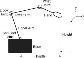
The height and depth specify the location of the tip of the gripper relative to the center of the base, which is the origin. A right-hand coordinate system is shown in Figure 15-3. It is intended to show the respective axis directions, although the origin should be located at the center of the base. Ignore the coordinate system for now and assume that the robot is in the X-Y plane. Note that rotations are measured counterclockwise around a joint.
As you traverse the arm from the base to the tip, the angles of the joints add up to determine the angle of each link measured with respect to the horizontal. In Figure 15-3, the shoulder is about 110 degrees with respect to the base, the elbow is at −95 degrees with respect to the upper arm, and the wrist is at −30 degrees with respect to the lower arm. (The diagram is not drawn to scale.)
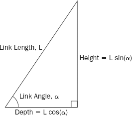
Consider each link as a simple straight line that is the hypotenuse of a right-angled triangle. The contribution of each link to the total depth and height are the horizontal and vertical edges of this triangle and can be calculated based on the angle of the link, α, and its length, L. Figure 15-4 shows the side-on view of a single link, which might be the upper arm, lower arm, or hand.
For the L6 arm in the position in Figure 15-3, the calculations are shown in the following table:
Element | Length | Angle (Total) | Height | Depth |
|---|---|---|---|---|
Base to Shoulder (H) | 2.25" | 2.25 | 0.0 | |
Shoulder | 110° (110°) | |||
Upper Arm (L1) | 4.75" | 4.46 | −1.62 | |
Elbow | −95° (15°) | |||
Lower Arm (L2) | 4.75" | 1.23 | 4.59 | |
Wrist | −30° (−15°) | |||
Hand (L3) | 5.75" | −1.49 | 5.55 | |
Totals | 6.45 | 8.52 |
To determine the angles for each of the links, you need to take into account the way that the servo is fixed to the respective links and translate the servo angles to link angles. For example, when the shoulder servo has a setting of zero degrees, it is standing upright, i.e., the upper arm (L1) is at 90 degrees. A summary of the servo orientations and directions of travel is given in the following table:
Servo | Zero Position | Positive Direction (Increasing Angle) |
|---|---|---|
Base | Facing away from SSC—32 | Clockwise (right) |
Shoulder | Vertical | Lean backwards |
Elbow | Right angle to upper arm[a] | Bend down |
Wrist | In line with lower arm | Bend up |
Wrist Rotate | Horizontal | Counterclockwise (left) |
[a] If you look at the physical mounting of the elbow, you can see that the screws are offset so that it actually makes a 70-degree angle between the upper arm and lower arm when it is in the zero position. However, the software adjusts for this difference, so if you request an angle of zero for the elbow servo, it moves to make a 90-degree angle between the upper and lower arms. This offset is necessary because if the upper arm moved all the way to a servo setting of +90, it would hit the cross bracing in the lower arm. It is free to move to _90 in the opposite direction, although this is not advisable. In addition, the simulation uses a direction of rotation for the elbow that is opposite to the real arm, but this is hidden from you by the arm service. | ||
The depth and height show the position of the tip relative to the base. The height immediately translates to the Y coordinate in 3D space. However, the base can also rotate, so to obtain the X and Z coordinates you use the depth and the angle of base rotation. The depth corresponds to the radius of rotation measured on the ground (looking down at the arm from above).
To complicate matters, the base servo starts with the arm facing away from the SSC-32 controller board and it moves clockwise for increasing servo angles. If you are sitting beside the robot with the SSC-32 on your right, which is the view that first appears in the simulation, the X coordinate is always negative. Unlike the simulation, the real L6 cannot rotate by 180 degrees in either direction.
Combining all of these calculations results in the (X, Y, Z) position of the tip, given all of the servo angles. The code to do this is in a routine called ForwardKinematics, which is in Lynx6Arm.cs in the folder ProMRDSChapter15LynxmotionLynx6Arm. There is no point in reproducing the code here. If you are interested you can read through it.
Unless you have a very expensive arm, it is not possible to instruct it to go to a particular location in 3D space. Instead, you must calculate the values of all of the joint angles that correspond to the desired pose. This is called inverse kinematics, and you can find books with entire chapters dedicated to this topic.
As noted in Chapter 8, there are spreadsheets available on the Lynxmotion website for performing the forward and inverse kinematics calculations.
The Lynx6Arm service developed for this chapter was based on the original MRDS V1.0 code from the Lynxmotion website. In order to simplify the code, the Lynx Inverse Kinematics service was dropped and replaced by direct calculations inside the Lynx6Arm service itself. The algorithm was taken from Hoon Hong's ik2.xls spreadsheet for inverse kinematics posted on the Lynxmotion website. This is much simpler and easier to understand (and debug).
Providing a general service to solve the kinematics equations is a good idea, but every articulated robot has a different design, and it is a difficult problem to generalize. For example, a humanoid robot is a very different configuration from a robotic arm, but it still needs to solve inverse kinematics equations to make it walk.
If you followed the forward kinematics discussion, then you can imagine the inverse kinematics as the opposite set of calculations. Unfortunately, in general, there can be more than one possible solution or no solution at all.
Multiple solutions to reaching a particular 3D point in space occur when you have a wrist. You can tilt your wrist up or down, but the tips of your fingers can still be at the same place. To resolve this issue, you must also specify the tilt angle of the wrist. This is also important when using a gripper because you often want to have the gripper horizontal when it picks up an object. That means four pieces of information are required: X, Y, Z, and P, where P is the wrist/hand angle.
There might be no solution if you have specified a point that is outside the reach of the robot. Even close to the robot, there can be places that it cannot reach. For example, the Lynx 6 would have a hard time trying to scratch itself—for the same reason that you cannot touch your elbow with your fingers (the elbow on the same arm as your hand—not the other arm, that's cheating!).
Even if you do find a solution to the equations, the arm might be unstable if placed in that position. The Lynx6Arm service places some constraints on the servo angles to try to avoid overtaxing the servos. However, it is still possible to damage the arm if you are not careful.
The Lynx 6 Robotic Arm Combo Kit for PC available from Lynxmotion is a relatively inexpensive kit that the authors use to demonstrate many of the principles of robotic arms. For full details see www.lynxmotion.com/Category.aspx?CategoryID=25.
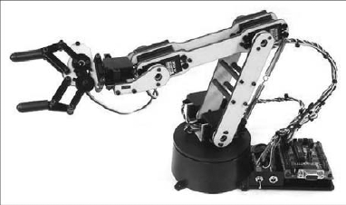
The L6 kit has six degrees of freedom: Base Rotate, Shoulder, Elbow, Wrist, Wrist Rotate, and Gripper. The somewhat cheaper L5 kit does not include the Wrist Rotate, but we recommend that you save your pennies and buy the L6 because the extra degree of freedom is useful. Figure 15-5 shows the L6 arm. The SSC-32 controller board is at the right-hand side and you can see the serial port socket.
Building the arm will take you several hours. The assembly instructions are available online at the Lynxmotion website, and it might be wise to read them before you decide to buy an arm. As you build, consider the following:
The pieces are made out of lexan, which is very tough. They are laser cut, but the cuts don't go all the way through in some places. Pushing out the smaller holes can be difficult, and the pieces have very tight tolerances. You should carefully drill out the holes with the correct size drill bit, and you might want to use a small file to trim a little off the various tongues before fitting them into their mating slots.
An SSC-32 servo controller is supplied as part of the kit. It is already assembled so you don't need to do any soldering. It can handle up to 32 servos via a serial port connection with a PC. You can see the circuit board on the right-hand side in Figure 15-5. A very good manual is available for the SSC-32, and you should read it in conjunction with this chapter. It explains the format of the serial commands that can be sent to the arm. This information isn't necessary, but it gives you a better idea of the capabilities of the SSC-32.
Although the L6 arm comes with some sophisticated control software called RIOS (robotic arm interactive operating system), the objective of this book is to show you how to control it using MRDS. The Lynx6Arm service on the book's website (
www.proMRDS.comorwww.wrox.com) offers a simple interface for the arm with the advantage that you have the source code.LynxTerm is basic software that enables you to manipulate the robot's joints individually. The Motion Recorder service included in this chapter provides similar functionality for moving the joints. You can use either of these to test your arm once you have built it, although the assembly instructions refer to LynxTerm.
Of course, once you've built the arm you'll want to try it out. Before you do, you might want to consider the following:
Make sure that you have plenty of clear space around the robot. It might do unexpected things if you enter a bad value for a parameter or make a coding mistake.
Starting up the arm frequently results in it jerking. This happens because the L6 has no feedback from the servos. Consequently, when the SSC-32 powers up, it assumes that all of the servos are in their centered positions. In general, this is a bad assumption. The first time you try to move a servo, it might jump rapidly from its current position to the new position that you request. Therefore, try to hold up the arm when you start it up so that it does not have as far to travel. You can move the linkages carefully while it is powered off without damaging the arm.
The arm has a tendency to oscillate if you move it too fast or try to pick up very heavy loads. There are springs that can be attached between the elbow and the shoulder to try to compensate for the load (look carefully at Figure 15-5 just behind the upper arm), but these add extra load and might even exacerbate the problem for some arm positions.
However, the springs do stop the arm from slumping to the ground when the power is turned off. This helps to protect the arm, and minimizes jerking when the arm is initialized because it is more likely to be near its starting position. It's a good idea to reset the arm to the default position every time you use it before turning it off.
To make the robot more stable, it is highly advisable to screw it to a board or table. Unfortunately, this makes it difficult to move around if you want to take it somewhere to do a demo. Based on the length of the arm, a board 60cm by 90cm is more than big enough to cover the whole area that the arm can reach.
The code to control the L6 arm is not included with MRDS. A version of the code can be downloaded from the Lynxmotion website, but the companion websites for this book (www.wrox.com and www.ProMRDS.com) contain a heavily modified version that is used in the examples. This new version is used with the permission of Lynxmotion. All of the code is contained in the folder ProMRDSChapter15LynxmotionLynx6Arm.
There are two parts to the code: the Lynx6Arm service and the SSC32 service. The simulated Lynx 6 robotic arm is in the Chapter 8 folder.
Before you attempt to use the software, you need to connect your arm to a serial port on your PC and make the appropriate change to the code. The SSC32 service has COM1 hard-coded into the SerialPortConfig class in SSC32State.cs:
public class SerialPortConfig
    {
        //Serial port configuration parameters

        //Baud rate is 115.2k with both jumpers
        private int _baudRate = 115200;
        private Parity _parity = Parity.None;
        private int _dataBits = 8;
        private StopBits _stopBits = StopBits.One;
        // IMPORTANT: This is the COM port that will be used by the arm.
        // It is hard-coded here. There should be a config file associated
        // with this service, but this has not been implemented yet.
        private string _portName = "COM1";
        private int _timeout = 1000;
Note that there is a timeout value of one second. Don't touch the other serial port settings because they are set in the firmware on the SSC-32 controller board.
The Lynx6Arm service implements the MRDS generic Articulated Arm contract. This contract is used by the examples to communicate with the arm. It is also implemented in the simulator, so the same code works on both the simulator and the real arm in most cases.
The generic Articulated Arm contract included with MRDS has only a small number of requests. You can find the code under MRDS in samplesCommonArticulatedArmState.cs and ArticulatedArmTypes.cs.
The following requests are available for the generic contract in addition to the usual requests such as Get, Drop, and Subscribe:
SetJointTargetPose: Sets the pose for a single joint
SetJointTargetVelocity: Sets the velocity for a single joint
GetEndEffectorPose: Gets the pose of the end effector (using forward kinematics)
SetEndEffectorPose: Sets the pose of the end effector (changes all joints as necessary using inverse kinematics)
The standard set of requests might not be suitable for some applications. For example, there are no explicit requests to control the opening/closing of the gripper, although it can just be considered another joint. Humanoid robots might not have grippers, but a gripper is a fundamental feature of an arm—without a gripper an arm would be useless!
For basic operations, these requests are sufficient. In fact, you can control the arm using only SetJointTargetPose if you know all of the relevant joint positions for the trajectory of the arm. If the arm will be performing some repetitive task, you can just record the joint positions using the Motion Recorder service developed for this chapter and then replay them.
The Lynx6Arm service treats the gripper as the last joint in the set, but limits the angle to ±35 degrees because the gripper servo is a very lightweight servo, and it could become overloaded if the gripper mechanism were driven too far. In addition, be very careful when closing the gripper on an object so that you do not try to drive it too far.
There are no timing parameters for SetJointTargetPose so you are restricted to using whatever value is implemented in the service itself. SetJointTargetVelocity can be used to specify the maximum speed for joint motions. Its name might suggest that it starts a joint moving at a specified speed, but this is not the case.
The firmware on the SSC-32 has been designed so that a sequence of joint motion commands can be sent in quick succession and it will execute all of them. However, this is not an ideal approach. Unless the Time parameter is the same for all of the joints in a sequence, they will move to their destinations at different speeds. This is equivalent to Asynchronous PTP in KUKA terminology.
You can use GetEndEffectorPose to obtain the 3D coordinates of the EOA and the tilt angle of the wrist. Note that the wrist tilt angle is not the same as the angle of the wrist servo angle. The wrist tilt is the accumulation of all of the angles for all the joints and specifies how the wrist is tilted with respect to a horizontal line.
When you call GetEndEffectorPose, the Lynx6Arm service calls the SSC-32 service to query the arm. This means that the values returned should be current. This operation is done synchronously. In other words, the SSC-32 service sends a request to the SSC-32 and then waits for a reply. However, it does not guarantee that the arm is physically located at the corresponding location. If the arm's motion is restricted for any reason, the servo settings might not be reached. The SSC-32 is only telling you how it is pulsing the servos, not whether the servos are at the desired positions, which it has no way to know.
The EOA is at the tip of the gripper, but to pick up an object you need to position the gripper so that the object is at the TCP. There is a difference of about an inch (a couple of centimeters). It is a simple matter to change the kinematics code to calculate the TCP rather than the EOA. Open Lynx6Arm.cs, locate the following code, and reduce the value of L3:
// Physical attributes of the arm
float L1 = Conversions.InchesToMeters(4.75f);   // Length of upper arm
float L2 = Conversions.InchesToMeters(4.75f);   // Length of lower arm

// Not required
//float Grip = Conversions.InchesToMeters(3.5f);  // Length of gripper

// NOTE: The gripper is basically in two parts because it contains
// the wrist rotate joint which is NOT at the same place as the
// wrist joint.
// Measurements are:
// Wrist joint to rotate plate = 2.25"
// Rotate place to tip of fingers = 3.5"
// The actual length of the "hand" varies slightly depending on
// whether the gripper is open or closed.
// L3 measures the distance to the tip of the fingers or End Of Arm (EOA).
// A Tool Center Point (TCP) would be shorter than this.
// The rubber fingers are just over 1" long, so to keep the grip action
// happening on the fingers, then L3 needs to be shorter by about 0.5".
float L3 = Conversions.InchesToMeters(5.75f);   // Length of whole hand

float H = Conversions.InchesToMeters(2.5f);     // Height of the base
If you have an older Lynx 6 arm, you will have a yellow base instead of a black one. This base is a different height so you also need to modify the value of H. Note that the base height is measured up to the center of the shoulder servo.
The SetEndEffectorPose request performs the inverse kinematics calculations. You specify both the position and orientation (wrist tilt) of the end effector.
The SSC-32 has a command that sets multiple joints in motion at the same time but with an overall Time parameter, and SetEndEffectorPose uses this command. (Speeds can still be specified individually, and the motion will take the longer of the times specified or the time based on the speed.) This is basically the equivalent of the KUKA Synchronous PTP mode of operation.
One consequence of this is that motions specified using SetEndEffectorPose are usually much smoother than setting all of the joint angles (via multiple calls to SetJointTargetPose).
By now you should be familiar with the Dashboard. It includes a panel for controlling an arm and it will work with the Lynx6Arm service.
The generic arm contract requests do not allow for setting multiple joints simultaneously. KUKA created a new generic contract with a request called
SetMultipleJointAnglesfor just this purpose. However, the KUKA implementation is not backwardly compatible with the existing generic arm contract, so standard programs such as the Dashboard do not work with the KUKA simulator.
To try using the Dashboard, run the following command from a MRDS Command Prompt window (remembering that it has to be on one line):
dsshost -port:50000 -tcpport:50001-manifest:"ProMRDS/Config/Lynxmotion.Lynx6Arm.manifest.xml"-manifest:"ProMRDS/Config/Dashboard.manifest.xml"
For your convenience, a batch command file called LynxL6Arm.cmd is also provided.
When the Dashboard starts up, connect to localhost. You should see the lynx6arm in the services list. Make sure that you have enabled the articulated arm display under Tools
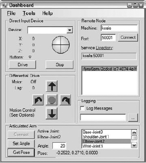
You can select a joint by clicking it. Enter a value for the angle and then click the Set Angle button. The joint will move to the specified angle. When you are first experimenting, use fairly small angles until you know how the arm will behave. You can use both positive and negative angles. If you click the Get Pose button, the current X, Y, Z coordinates of the EOA will display.
Clearly, moving the arm around in this fashion is tedious. The example is simply included here to illustrate that the generic arm contract works. An alternative way to control the arm is using one of the VPL programs in Chapter 12 and an Xbox game controller. The two VPL programs for robotic arms in Chapter 12 use the thumbsticks and buttons in different ways. This is deliberate, and highlights the difference between adjusting servo angles and specifying the position of the end effector. Some people will find one way more intuitive than the other, but in some situations both approaches are useful. Playing with an Xbox controller is a very good way to get a practical understanding of the different approaches to moving an arm.
The next step beyond the Dashboard is to use a more sophisticated application to control the arm. This chapter includes a service called the Motion Recorder. The service can be used with either the simulated arm or a real arm, so even if you don't have a Lynxmotion L6 arm you can still experiment with the simulator. This section explains how the Motion Recorder works and how to use it.
In the MRDS bin folder you will find a batch file called MotionRecorder.cmd. Run this batch file to start the Motion Recorder.
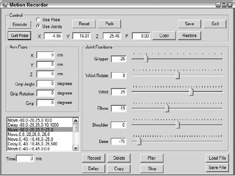
The Motion Recorder service enables you to move the arm around either by moving joints individually or by specifying a pose. You can save the arm positions to a file and then later replay the sequence of commands. The service GUI looks like Figure 15-7.
The purpose of the Motion Recorder is to help you develop applications. It could be improved in a lot of ways, but it is only intended as a simple tool.
You will notice some similarities between the Motion Recorder and the GUI for the Lynx arm simulation in Chapter 8. In fact, it can be used with the simulator if you want. To use the simulator, edit the manifest in the ProMRDSConfig directory called MotionRecorder.manifest.xml. At the bottom of the manifest you will see that the simulated arm is commented out (this is highlighted in the following code). Remove the commenting and instead comment out the real arm service, which is just above the simulated one.
<?xml version="1.0" ?>
<Manifest
  xmlns="http://schemas.microsoft.com/xw/2004/10/manifest.html"
  xmlns:dssp="http://schemas.microsoft.com/xw/2004/10/dssp.html"
  >
  <CreateServiceList>
    <ServiceRecordType>
        <dssp:Contract>http://schemas.tempuri.org/2007/11/
motionrecorder.html</dssp:Contract>
    </ServiceRecordType>
<!-- Use the real arm -->
    <ServiceRecordType>
        <dssp:Contract>http://schemas.coroware.com/2007/11/
lynx6arm.html</dssp:Contract>
    </ServiceRecordType>

<!-- Use the simulated arm
    <ServiceRecordType>
        <dssp:Contract>http://schemas.tempuri.org/2007/10/
SimulatedLynxL6Arm.html</dssp:Contract>
    </ServiceRecordType>
-- >
  </CreateServiceList>
</Manifest>
Now when you run the Motion Recorder, the simulator will start. You can play around as much as you like without potentially damaging your Lynx 6 arm.
The following is a brief description of how the Motion Recorder works. The user interface should be fairly intuitive. Three main files make up the application:
The MotionRecorderTypes.cs file should not require any explanation, as it is quite short.
MotionRecorder.cs does all the work of controlling the arm and is explained further in this section. It specifies the Lynx6Arm service as a partner. Notice that it uses the generic arm contract and creates a port called _lynxPort:
[Partner("Lynx6Arm", Contract = arm.Contract.Identifier,
    CreationPolicy = PartnerCreationPolicy.UseExisting, Optional = false)]
private arm.ArticulatedArmOperations _lynxPort =
    new arm.ArticulatedArmOperations();
A lot of the code in MotionRecorderUI.cs is for validating input data, reading and writing files, and so on. This has nothing to do with MRDS, but unfortunately it has to be included.
MotionRecorderUI.cs uses the standard process for a WinForm to communicate with the main service. (If you are unsure about how this works, refer back to Chapter 4. Only a very brief explanation is provided here.) It uses a set of classes that are defined in a similar way to operations for a service, except that it is not a full-service interface. Instead, it posts all of its requests using a single operation class and passes across an object that represents the function to be performed. This helps to reduce the number of operations in the main service's port set so that the limit of 20 operations is not exceeded.
For example, when the Form is first created it sends back a handle to itself to the main service. This lets the main service know that the Form is running so that it can enumerate the joints in the arm. In the Form, the code is as follows:
// Send a message to say that the init is now complete
// This also passes back a handle to the Form
_fromWinformPort.Post(new FromWinformMsg(FromWinformMsg.MsgEnum.Loaded, null,
this));
Back in the main service, the FromWinformMsg handler processes the request and executes the appropriate code based on the command type, which in this case is Loaded:
// Process messages from the UI Form
IEnumerator<ITask> OnWinformMessageHandler(FromWinformMsg msg)
{
    switch (msg.Command)
    {
        case FromWinformMsg.MsgEnum.Loaded:
            // Windows Form is ready to go
            _motionRecorderUI = (MotionRecorderUI)msg.Object;
            SpawnIterator(EnumerateJoints);
            break;
EnumerateJoints issues a Get request to the Lynx6Arm service to get its state. Notice that it does this in a loop because the arm service might not be up and running properly, in which case there will be a Fault. To ensure that it does not loop forever, there is a counter:
IEnumerator<ITask> EnumerateJoints()
{
    int counter = 0;
    arm.ArticulatedArmState armState = null;

    // Get the arm state because it contains the list of joints
// Wait until we get a response from the arm service
// If it is not ready, then null will be returned
// However, we don't want to do this forever!
while (armState == null)
{
// Get the arm state which contains a list of all the joints
yield return Arbiter.Choice(
_lynxPort.Get(new GetRequestType()),
delegate(arm.ArticulatedArmState state) { armState = state; },
delegate(Fault f) { LogError(f); }
);
// This is not good error handling!!!
if (armState == null)
{
counter++;
if (counter > 20)
{
Console.WriteLine("***** Could not get arm state. Is the arm
turned on? *****");
//throw (new Exception("Could not get arm state!"));
yield break;
}
// Wait a little while before trying again .
yield return Arbiter.Receive(false, TimeoutPort(500),
delegate(DateTime now) { });
}
}The armState contains a list of the joints. A list of the joint names is created and then the Form is updated using FormInvoke, which executes a delegate in the context of the Form. The Form contains the function ReplaceArticulatedArmJointList, which updates the list of joint names inside the Form so that it can also refer to them by name:
// Create the new list of names
    _jointNames = new string[armState.Joints.Count];
    for (int i = 0; i < armState.Joints.Count; i++)
    {
        _jointNames[i] = armState.Joints[i].State.Name;
    }

    // Now update the names in the Form so that it can do
    // whatever it needs to with them as well
    WinFormsServicePort.FormInvoke(delegate()
    {
        _motionRecorderUI.ReplaceArticulatedArmJointList(_jointNames);
    });
In addition to setting the joint names, the initial joint angles are also set, but the code is not shown here. That completes the startup process.
The Motion Recorder does not automatically record anything. You must click the Record button (near the bottom of the window) to record the current command. You can play around using the slider controls, and as you move them the arm will follow (and the angle values in the textboxes will update). When you are happy with the position of the arm, you can record it. By doing this repeatedly, you can build up a complete sequence of motions to perform a particular task.
Note
Warning: Do not move the sliders too fast!
The UI contains four basic areas. At the top is the Control Panel, which enables you to execute motion commands. Next are the Arm Pose and Joint Positions panels, which provide values for motions. Finally, there is an area for recording, saving, and replaying commands.
The most important button is the Execute button, which calls the main service to perform either a SetEndEffectorPose if the Use Pose radio button is selected, or a sequence of separate SetJointTargetPose operations (one for each joint) if the Use Joints radio button is selected. These two operations are the crux of the application, so the code for them is discussed here.
As you move the sliders around, the trackbar controls continually fire off requests to the main service to move the corresponding joints. Once the main service has decoded the FromWinformMsg it executes the MoveJoint function using the values passed from the Form:
void MoveJoint(string name, float angle)
{
    arm.SetJointTargetPoseRequest req = new arm.SetJointTargetPoseRequest();
    req.JointName = name;
    AxisAngle aa = new AxisAngle(
        new Vector3(1, 0, 0),
        (float)(Math.PI * ((double)angle / 180)));

    req.TargetOrientation = aa;

    _lynxPort.SetJointTargetPose(req);
}
Notice that the SetJointTargetPoseRequest requires the name of the joint and the target angle, expressed as an AxisAngle. By convention, the axis angles are all with respect to the X axis. In addition, the angle from the Form is in degrees, so it has to be converted to radians.
When Use Joints is selected, the Execute button invokes a different method in the main service called MoveMultipleJoints, but this simply calls MoveJoint for each of the joints because the generic arm contract does not have a request to set multiple joints at the same time. The disadvantage of this approach is that the different joint movements are not coordinated.
Conversely, if Use Pose is selected when the Execute button is pressed, it sends a request to run the MoveToPosition function in the main service. This function sends a SetEndEffectorPose request to the Lynx6Arm service, but first it has to create a quaternion for the pose. This is a somewhat painful process that is not helped by the fact that the proxy versions of the classes don't have the necessary static methods. After several lines of code, the request is finally sent. Then the wrist rotate angle and the gripper are set independently because SetEndEffectorPose does not do these:
public SuccessFailurePort MoveToPosition(
    float mx, // x position
    float my, // y position
    float mz, // z position
    float p, // angle of the grip
    float w, // rotation of the grip
    float grip, // distance the grip is open
    float time) // time to complete the movement
{
    // Create a request
    arm.SetEndEffectorPoseRequest req = new arm.SetEndEffectorPoseRequest();
    Pose rp = new Pose();
    Vector3 v = new Vector3(mx, my, mz);
    rp.Position = v;
    physicalmodel.Quaternion q = new physicalmodel.Quaternion();
    q = physicalmodel.Quaternion.FromAxisAngle(1, 0, 0,
Conversions.DegreesToRadians(p));
    Quaternion qp = new Quaternion(q.X, q.Y, q.Z, q.W);
    rp.Orientation = qp;
    req.EndEffectorPose = rp;
    _lynxPort.SetEndEffectorPose(req);

    // Set the positions of the wrist rotate and the gripper as well
    MoveJoint(_jointNames[(int)lynx.JointNumbers.WristRotate], w);
    MoveJoint(_jointNames[(int)lynx.JointNumbers.Gripper], grip);

    // Now return success
    SuccessFailurePort responsePort = new SuccessFailurePort();
    responsePort.Post(new SuccessResult());
    return responsePort;

}
Note a couple of advantages in using SetEndEffectorPose. You can set precisely where the arm will go by entering values into the Arm Pose panel. You can also specify the tilt angle of the gripper, which is important if you want the robot to pick something up. More importantly, the motion is better coordinated because, as explained earlier, it sends a single command to the SSC-32 to move all the joints.
The disadvantage of using the Arm Pose panel is that it isn't always easy to pick valid values. Moreover, sometimes the results might be a little surprising. If the arm doesn't move, look in the MRDS DOS command window for an error message. It is possible that you selected an invalid pose, which causes the arm service to generate a Fault.
When you click the Get Pose button, the code sends a FromWinformMsg request to the main service containing the command GetPose. In the main service, the FromWinformMsg handler decodes the command and calls GetArmHandler. This handler makes a GetEndEffectorPose request to the Lynx6Arm service and then uses FormInvoke to return the results to the Form, where they appear in the textboxes across the top. The slider controls are also updated to match the current positions of the joints. A Copy button beside the pose values enables you to transfer the pose information to the Arm Pose textboxes.
Alternatively, you can enter values into the textboxes beside the joint sliders. Then when you click Execute (with Use Joints selected), the joint angles will be set.
The Save button provides a quick way to save all the values in the Arm Pose and Joint Position textboxes. You can get them back later using Restore.
The Reset button sets all of the angles to zero, which should be the initial setting when the arm starts up. Park sends the arm to a "parked" position, but it is quite arbitrary. You can change the joint angles for each of these at the top of the main service:
// Joint angles for the Reset and Park commands
float[] _resetAngles = { 0, 0, 0, 0, 0, 0 };
float[] _parkAngles = { 0, 20, −50, 30, 0, 0 };
The remaining buttons across the bottom of the window perform the following functions:
Record: Saves the values of either the Arm Pose or Joint Positions, depending on whether Use Pose or Use Joints is selected, into the command history list at the bottom left
Delay: Adds a delay command to the command history list using the value in the Time field
Delete: Removes the currently selected item from the command history list
Copy: Copies the values from the currently selected command to either the Arm Pose or Joint Positions textboxes depending on the type of command that is selected
Play: Replays all of the commands in the list starting from the top
Stop: Stops replaying commands
Load File: Loads a previously saved command history list file
Save File: Saves the command history list to a CSV file
Saved command history files are comma-separated value files. These are plain text and can be edited with Notepad, or loaded into Excel. An example is given in the next section. You might find it quicker to edit a file rather than use the Motion Recorder once you have saved a few key commands. Just be careful not to mess up the format.
"Pick and place" is a very common operation for robotic arms. They can spend the whole day picking things off a conveyor belt and dropping them into bins—a mindless task that you would probably find exceedingly boring.
The basic principle is to program the arm so that it knows where to go to get an object (pick) and where to go to put it down (place). Even today, many robotic arms are manually programmed by moving them through a sequence of motions and recording the path.
A saved command history file is included in the software package on the book's website (www.proMRDS.com and www.wrox.com). It should be in the folder with the Motion Recorder source files and is called take_object.csv. The contents of this file are as follows:
Move,-80,0,-20,25,0,10,0
Delay,-80,0,-20,25,0,10,1000
Move,-80,0,-20,25,0,-25,0
Move,0,0,-20,25,0,-25,0
Move,0,-40,-10,45,0,-25,0
Delay,0,-40,-10,45,0,-25,500
Move,0,-40,-10,45,0,0,0
Move,0,-20,-10,45,0,0,0
Delay,0,-20,-10,45,0,0,1000
Move,0,-40,-10,45,0,0,0
Delay,0,-40,-10,45,0,0,500
Move,0,-40,-10,45,0,-25,0
Move,0,-20,-10,45,0,-25,0
Move,0,0,-20,25,0,-25,0
Move,-80,0,-20,25,0,-25,0
Delay,-80,0,-20,25,0,-25,500
Move,-80,0,-20,25,0,10,0
Notice that the file only contains Move and Delay commands. There is no particular reason for this other than that it was easier to move the sliders than to figure out coordinates. However, it could use Pose commands.
This file executes the following basic steps:
Swing the arm to the left (which should be to where you are sitting) and open the gripper in expectation of being handed something.
Close the gripper. The gripper setting is for a AA battery. If you want to use a different object, you should first practice with the Motion Recorder and set the gripper value accordingly. You don't want to force the gripper too far past the point where it contacts the object.
Turn the arm back so it faces straight ahead and put the object down.
Raise the arm and pause for effect. (This might be an appropriate point for applause.)
Pick the object up again.
Take it back and drop it where it came from. If you are not ready to catch it, the object—whatever it is—will fall on the ground.
To begin, load the file into the Motion Recorder and play it without using an object. Just sit and watch. Then you can try handing an object to the arm when it extends its hand out to you.
This sequence can definitely be improved, but that isn't the point. What you have is a program that enables you to easily determine the necessary joint parameters for a sequence of operations. With this knowledge you can write services that replay the commands, or perhaps generate commands automatically based on some formula.
You need to play and replay your motion sequence repeatedly, looking for flaws. One of the main problems is that the arm might take a shortcut to its destination that takes it too close to an obstacle. Similarly, when picking up or putting down an object, you need to make clear the up and down movements. Don't simply drag the object off to its new location straight away because that is exactly what might happen—it drags along the ground.
When moving objects around, you need to remember where you put them. The arm cannot sense anything in its environment. Another problem is that the arm needs a certain amount of clearance to put down and pick up an object. Placing objects too close together is almost certain to result in some of them getting knocked over. The further the arm is extended, the less leeway there is to "reach over" an object to get to one behind it.
You will find that the Lynx 6 arm tends to wave around (oscillate) when it is extended a long way. If it waves too much, it can knock over other objects. The examples using dominoes in the simulation in Chapter 8 are probably not possible with a real L6.
In addition, remember that the gripper on the arm can only approach an object along a radial line from the base of the arm out to the tip. The wrist rotate servo is no help in turning the end of the arm to face a different direction—it just tips the gripper on its side. You might therefore find that it is easier to place objects in semi-circular patterns, rather than straight lines.
MRDS includes support for a webcam. If you start a webcam service and run the Dashboard, you will see your webcam listed. Selecting it brings up a separate window to show the video stream. The source code for this is included in the Dashboard service in Chapter 4.
If you placed a camera above your arm looking down, it should be a simple matter to locate objects in the image for the arm to pick up. (The simulated arm in Chapter 8 includes a camera overlooking the arm, as well as a camera mounted just behind the gripper.) As long as the objects are a significantly different color from any of the colors on the ground, you can use image subtraction to separate objects out from the background. You first take an image of the empty area as a reference. Then, as objects are placed in front of the robot, you subtract the original image from the current image. Anything that is not ground will stand out.
A blob tracker example included with MRDS is another alternative. It can be trained to follow objects of different colors. Regardless of how you locate the objects in the image, you have to calibrate the arm to the image. The simplest way to do this is probably to position the arm roughly near the four corners of the image and use GetEndEffectorPose to determine the X and Z coordinates (the Y coordinate is the height, which you can't tell from an overhead image). By interpolating between these points in both directions, you can determine the coordinates of any point in the image.
Note that your camera needs to be mounted directly overhead and looking straight down. If it is off to one side, then perspective will make the interpolation nonlinear. This is left for you as an exercise.
After completing this chapter successfully, you should have a good grounding in using robotic arms. If you are a student of mechatronics, then you might feel that something is missing, and there is—a heap of complex equations. If you want more details, visit the KUKA Educational Framework website (www.kuka.com).
Robotic arm applications are limited only by your imagination (and, of course, the physical constraints on your arm).
The next chapter shows you how to write services to run on an onboard PC running Windows CE or a PDA using the .NET Compact Framework (CF).