
This chapter explains how to create articulated entities such as robotic arms and jointed robots in the simulation environment. Wheeled robots are fine for some applications, but sometimes you need a robot that can reach out and grab things.
The primary mechanism for defining articulated entities is the Joint object. This chapter begins by describing how to use a joint to join two entities and all of the options that are available. Then you will learn how to build a robotic arm with multiple joints.
A Joint is an object that joins two entities together. It has up to six degrees of freedom (three angular and three linear), which means it can be configured in a number of different ways. The simplest joint is a revolute joint, which has a single angular degree of freedom unlocked, and it behaves much like a door hinge. A joint with a single linear degree of freedom unlocked would operate somewhat like a shock absorber or a worm gear, with the joined entities able to move closer or farther along a single direction. A joint with all degrees of freedom unlocked can move in any direction and rotate and twist into any possible orientation.
The Joint class is defined in the Microsoft.Robotics.PhysicalModel namespace, which is implemented in the RoboticsCommon DLL. This Joint class is available for all services to use, not just simulation services. Its most important member is the JointProperties member called State. These properties specify the behavior of the joint when it is created in the physics engine.
A subclass of the Joint class called PhysicsJoint is defined in the Microsoft.Robotics.Simulation.Physics namespace, which is implemented in the PhysicsEngine DLL. This object contains some additional data that is used by the physics engine; it also includes some additional methods. This is the object you must use when interacting with the physics engine. It is simple to convert a Joint object to a PhysicsJoint object and back again, as you'll see in the example code in this chapter.
Before you look in detail at the JointProperties class, it is important to understand the joint frame. A frame is a set of three axes that represent one coordinate system relative to another. This concept should be familiar to those readers who have worked with computer graphics. In a typical graphics scene, each object has its own frame relative to the world coordinates that determines its position and orientation. In graphics coordinates, we usually label the three axes in a frame as the X axis, the Y axis, and the Z axis.
Frames are used to specify the orientation of a joint as well. The three axes in a joint frame are called the local axis, the normal axis, and the binormal axis, as shown in Figure 8-1.
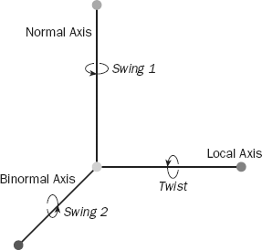
The joint frame follows the right-handed convention, meaning positive rotations around each axis are in the direction the fingers on your right hand curl when your thumb is pointed along the positive axis. The frame may be completely defined by specifying only two of the axes because the axes are always at right angles to each other and the third axis can be constructed by taking the cross product of the other two.
The joint names each angular degree of freedom (DOF), as shown in Figure 8-1. The Twist DOF is associated with rotations around the local axis, the Swing1 DOF is associated with rotations around the normal axis, and the Swing2 DOF is associated with rotations around the binormal axis.
The joint properties define how the joint behaves and how it attaches to the entities it joins. A joint may contain a reference to a JointAngularProperties class to unlock one or more angular degrees of freedom. It may also contain a reference to a JointLinearProperties class to unlock one or more linear degrees of freedom. It must always contain a two-element array of EntityJointConnector references to specify how it attaches to each entity.
The following sections describe the various members of the JointAngularProperties class, the JointLinearProperties class, the EntityJointConnector class, and other associated classes. These properties are explored in more detail in sample code following the descriptions.
The following table lists the members of the JointAngularProperties class:
The following table lists the members of the JointLimitProperties class:
Member | Description |
|---|---|
Specifies the angular or linear limit for the joint. Angular limits are expressed in radians. | |
Floating-point value that specifies the "bounciness" of the joint as it moves against the limit | |
| Spring properties that define a "soft limit." If the |
The following table lists the members of the JointDriveProperties class:
The following table lists the members of the JointLinearProperties class:
Member | Description |
|---|---|
The initial target position and velocity for the linear degrees of freedom for the joint | |
The DOF mode for each linear degree of freedom: locked, limited, or free. If limited, the motion of the joint along each axis is constrained by the | |
The drive characteristics of the joint along each of the respective axes | |
Only a single |
The joint is anchored to each entity at a point and orientation specified by an EntityJointConnector, which has the following members:
The following table lists the members of the JointProperties class:
Member | Description |
|---|---|
An array of two | |
| A reference to a |
| A reference to a |
This Boolean property specifies whether collision detection checks should be performed between the entities connected by this joint | |
This is the maximum force or torque that can be applied to the joint. If these limits are exceeded, the joint "breaks" and ceases to function. They should be set to similar values, and setting them to 0 ensures that the joint will never break. | |
| The name of the joint. Each joint should have a unique name. |
| The physics engine provides a way to correct large joint errors by projecting the joint back to a valid configuration. |
The best way to gain a good understanding of these various joint properties is to build a sample program that creates a variety of joints with various properties to see how they work.
Open the Chapter 8 solution in ProMRDSChapter8 and then open the TestBench.cs file in the TestBench project. This TestBench service is a basic simulation service much like Simulation Tutorial 1 or the Referee service from the previous chapter. Its purpose is to create a very long box called TestBenchEntity and then to create a number of test joints connected to SingleShapeEntities so that you can experiment with various joint parameters. It also creates a camera pointed at each joint so that it is very easy to switch to a view that shows the joint of interest.
Before getting into the details about the joints created in the PopulateWorld method, it is important to define a new class, which you'll use for the segments of articulated entities. This class inherits from SingleShapeEntity and is called SingleShapeSegmentEntity. It adds an additional property called CustomJoint, which is of type Joint. The entire definition of this class is shown here:
/// <summary>
/// Defines a new entity type that overrides the ParentJoint with
/// custom joint properties.  It also handles serialization and
/// deserialization properly.
/// </summary>
[DataContract]
public class SingleShapeSegmentEntity: SingleShapeEntity
{
    private Joint _customJoint;

    [DataMember]
    public Joint CustomJoint
    {
        get { return _customJoint; }
        set { _customJoint = value; }
    }

    /// <summary>
    /// Default constructor
    /// </summary>
    public SingleShapeSegmentEntity() { }

    /// <summary>
    /// Initialization constructor
    /// </summary>
    /// <param name="shape"></param>
    /// <param name="initialPos"></param>
    public SingleShapeSegmentEntity(Shape shape, Vector3 initialPos)
    : base(shape, initialPos)
    {
    }

    public override void Initialize(
        Microsoft.Xna.Framework.Graphics.GraphicsDevice device,
        PhysicsEngine physicsEngine)
    {
        base.Initialize(device, physicsEngine);

        // update the parent joint to match our custom joint parameters
        if (_customJoint != null)
{
If(ParentJoint != null)
PhysicsEngine.DeleteJoint((PhysicsJoint)ParentJoint);
// restore the entity pointers in _customJoint after deserialization
if (_customJoint.State.Connectors[0].Entity == null)
_customJoint.State.Connectors[0].Entity = FindConnectedEntity(
_customJoint.State.Connectors[0].EntityName, this);
if (_customJoint.State.Connectors[1].Entity == null)
_customJoint.State.Connectors[1].Entity = FindConnectedEntity(
_customJoint.State.Connectors[1].EntityName, this);
ParentJoint = _customJoint;
PhysicsEngine.InsertJoint((PhysicsJoint)ParentJoint);
}
}
VisualEntity FindConnectedEntity(string name, VisualEntity me)
{
// find the parent at the top of the hierarchy
while (me.Parent != null)
me = me.Parent;
// now traverse the hierarchy looking for the name
return FindConnectedEntityHelper(name, me);
}
VisualEntity FindConnectedEntityHelper(string name, VisualEntity me)
{
if (me.State.Name == name)
return me;
foreach (VisualEntity child in me.Children)
{
VisualEntity result = FindConnectedEntityHelper(name, child);
if (result != null)
return result;
}
return null;
}
/// <summary>
/// Override the base PreSerialize method to properly serialize joints
/// </summary>
public override void PreSerialize()
{
base.PreSerialize();
PrepareJointsForSerialization();
}
}This entity takes advantage of the fact that the simulation engine creates a fixed joint between a child and parent entity to join them together. In its override of the Initialize method, it first calls base.Initialize, which will, among other things, create the ParentJoint, which joins this entity to its parent entity if it is a child entity. If the CustomJoint has been defined, the Initialize method deletes the rigid ParentJoint that was automatically created and creates a new ParentJoint based on the properties of the CustomJoint. It is then very easy to define custom joints between child and parent entities simply by specifying the properties of CustomJoint.
This class also has some special code to handle proper serialization and deserialization of joints. A joint contains two connectors that each have a reference to the entity that is connected. When the SingleShapeEntity entity is serialized, either to be copied to disk or sent in a message to a service on another node, these entity references cannot be serialized; therefore, when a segment entity is deserialized, its entity references must be restored. This is done by overriding the PreSerialize method with a new method that calls PrepareJointsForSerialization after calling the base class PreSerialize.
PrepareJointsForSerialization is a method defined on VisualEntity that uses reflection to traverse all the fields in the entity to search for joints. When it finds a joint, it writes the name of the entity referenced by each EntityJointConnector into the EntityName field of each connector. This property is correctly serialized and it provides the information necessary to restore the entity connection after deserialization.
When a SingleShapeSegmentEntity is deserialized and then initialized, it eventually executes the code in the Initialize method override that checks whether either of the entity connectors is null. If so, the FindConnectedEntity method is used to traverse to the parent entity and then through all of the children entities to find an entity with the name contained in the EntityName property. When the entity is found, the reference to that entity is restored in the connector.
The SingleShapeSegmentEntity provides a SingleShapeEntity that supports custom ParentJoints and proper serialization and deserialization of joint objects within the entity. It is a simple matter to add the relevant code to other entity types by subclassing them to give them this same functionality.
Now you are ready to define a test bench to experiment with the various joint properties. In the next few sections, you'll add five different types of joints to the test bench so that you can see how they work.
In the PopulateWorld method in TestBench.cs, you begin by creating sky and ground entities as usual. Then you create a box entity that is 50 meters long. You will attach other entities to this box at two-meter intervals.
The first joint is the simplest possible revolute joint, with one degree of freedom:
// Simple single DOF joint
name = "1DOF";
segment = NewSegment(position + new Vector3(0, 0.5f, 0), name);
angular = new JointAngularProperties();
angular.TwistMode = JointDOFMode.Free;
angular.TwistDrive = new JointDriveProperties(JointDriveMode.Position,
    new SpringProperties(500000, 100000, 0), 100000000);
connectors = new EntityJointConnector[2];
connectors[0] = new EntityJointConnector(
    segment,
    new Vector3(0,1,0),
    new Vector3(1,0,0),
    new Vector3(0, -segment.CapsuleShape.State.Dimensions.Y/2 -
                   segment.CapsuleShape.State.Radius, 0));

connectors[1] = new EntityJointConnector(
    benchEntity,
    new Vector3(0,1,0),
    new Vector3(1,0,0),
    new Vector3(position.X, position.Y + 0.25f, position.Z));

segment.CustomJoint = new Joint();
segment.CustomJoint.State = new JointProperties(angular, connectors);
segment.CustomJoint.State.Name = name + "-twist";
benchEntity.InsertEntityGlobal(segment);
AddCamera(position, name);
position.X += 2;
The name variable is the base name for the segment, joint, and camera that will be created. You begin by creating a new SingleShapeSegmentEntity at the position defined by the position variable but raised up by half a meter so that its button rests on the top of the testbench.
Because this will be a revolute joint, you define a new JointAngularProperties variable and free the TwistMode degree of freedom. Recall from Figure 8-1 that the TwistMode degree of freedom is associated with the local axis.
Now you define the drive characteristics that will move the joint around this degree of freedom. The JointDriveProperties specify that you will be changing the position of the joint, rather than its velocity. They also specify the spring properties of the joint and the maximum torque that can be applied to the joint to force it to move to its target position. The spring properties enable a spring coefficient and a damping coefficient to be specified. The spring coefficient describes the amount of force that will be applied to the joint to move it toward its target position proportional to the distance from that target position. The damping coefficient roughly represents the friction of the joint to move. You'll examine the effect of lowering the damping coefficient in the second joint you create.
Next, the joint connectors are defined. The first connector attaches to the SingleShapeSegment entity you just created. In addition to the entity, the connector allows the local axis, the normal axis, and the connection point to be specified. In this case, you define the local axis to lie along the X axis (1,0,0) and the normal axis to lie along the Y axis (0,1,0). This leaves the binormal axis to lie along the Z axis (0,0,1) even though it is not specified here. The final parameter is the location on the segment entity where the joint is attached. The coordinates specified here are relative to the origin of the segment entity. You specify the bottom-most point of the capsule shape.
The next connector references the TestBenchEntity. It defines the normal and local axes the same way. Later you'll examine what happens if they are defined differently in the two connectors. The connection point is specified on the top surface of the testbench with X and Z coordinates according to the current position variable.
Now you create a Joint object and assign it to the CustomJoint property. You create a new JointProperties object using the angular joint properties and the joint connectors that you've already defined and assign it to CustomJoint.State. You give the joint a name and then insert the SingleShapeSegmentEntity as a child of the TestBenchEntity. You use InsertEntityGlobal because the coordinates you have given the segment entity are defined in world space, not relative to the TestBenchEntity.
Finally, create a camera that will look right at the joint you've just created. Run the TestBench manifest by typing the following in the MRDS command window. Alternatively, you can set the TestBench project as the StartUp project and then press F5 to run it.
C:>cd "Microsoft Robotics Studio (1.5)"

C:Microsoft Robotics Studio (1.5)>testbench
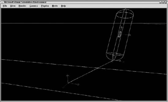
You should see a simulation window open with a scene similar to the one shown in Figure 8-2.
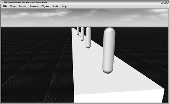
Press the F8 key once to switch the main camera to the 1DOF_cam camera to get a view of the segment entity you just created and attached. The TestBench manifest also runs the JointMover service, which can be used to move the joints you've specified. The user interface for this service is shown in Figure 8-3.
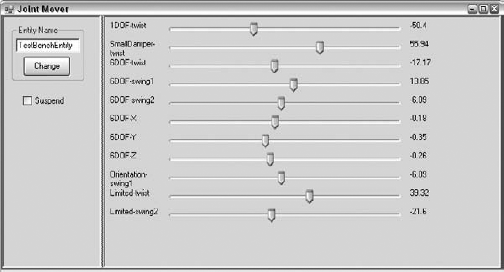
Each slider on the Joint Mover window corresponds to a degree of freedom in a joint on the entity specified in the Entity Name box. For scenes with multiple jointed entities, you can type a new entity name in the Entity Name box and press the change button to select the new entity. The sliders will reconfigure to match the joints in the new entity.
You can use the Suspend checkbox to set the top-level parent of the entity to kinematic and raise it off the ground a bit. This can be useful to test the joint movement of an entity that rests on the ground.
Slide the 1DOF-twist slider on the Joint Mover window to move the joint back and forth, as shown in Figure 8-4.
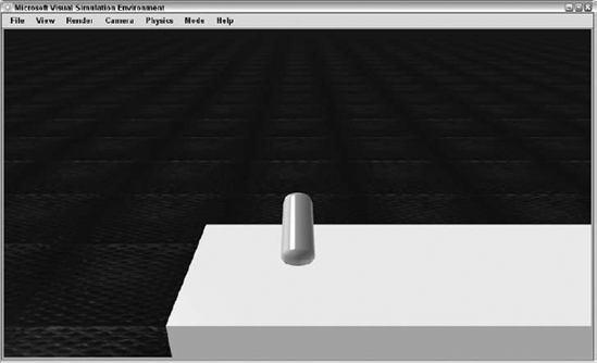
As you move the slider back and forth, the joint rotates around the X axis between 2180 degrees and 180 degrees. Note that if you move the slider quickly, the motion of the entity lags slightly behind.
For the next experiment, you'll create a joint with a much smaller damping coefficient on the drive to see how that affects the behavior of the joint. Here is the code for the "SmallDamper" joint:
// A joint with a very small damping coefficient on the drive
name = "SmallDamper";
segment = NewSegment(position + new Vector3(0, 0.5f, 0), name);
angular = new JointAngularProperties();
angular.TwistMode = JointDOFMode.Free;
angular.TwistDrive = new JointDriveProperties(JointDriveMode.Position,
    new SpringProperties(50000000, 100, 0), 100000000);
connectors = new EntityJointConnector[2];
connectors[0] = new EntityJointConnector(
    segment,
    new Vector3(0, 1, 0),
    new Vector3(1, 0, 0),
    new Vector3(0, -segment.CapsuleShape.State.Dimensions.Y / 2 -
                    segment.CapsuleShape.State.Radius, 0));

connectors[1] = new EntityJointConnector(
    benchEntity,
    new Vector3(0, 1, 0),
    new Vector3(1, 0, 0),
    new Vector3(position.X, position.Y + 0.25f, position.Z));

segment.CustomJoint = new Joint();
segment.CustomJoint.State = new JointProperties(angular, connectors);
segment.CustomJoint.State.Name = name + "-twist";
benchEntity.InsertEntityGlobal(segment);
AddCamera(position, name);
position.X += 2;
This joint definition is identical to the previous 1DOF joint except for the damping coefficient specified in the SpringProperties of the TwistDrive. The damping coefficient used is 100 instead of the previous value of 100000.
Run the TestBench manifest again and select the "SmallDamper_cam" camera to look at the second joint. Move the SmallDamper-twist slider in the Joint Mover window to move the joint in the same way as you moved the first joint. You should notice that the joint is much more responsive and crisp in its movements. There is little or no lag between the movement of the slider and the movement of the joint. The damping coefficient can be a useful parameter to model the friction of the joint. Be careful not to make this value too large, though. A large damping coefficient relative to the spring coefficient can mean that the joint will never quite reach the target position when it is moved.
Next, you'll define a joint with all six degrees of freedom unlocked. The code for this joint is shown here:
// A joint with all 6 DOF free
name = "6DOF";
segment = NewSegment(position + new Vector3(0, 0.5f, 0), name);
angular = new JointAngularProperties();
angular.TwistMode = JointDOFMode.Free;
angular.Swing1Mode = JointDOFMode.Free;
angular.Swing2Mode = JointDOFMode.Free;
angular.TwistDrive = new JointDriveProperties(
    JointDriveMode.Position, new SpringProperties(50000000, 100, 0), 100000000);
angular.SwingDrive = new JointDriveProperties(
    JointDriveMode.Position, new SpringProperties(50000000, 100, 0), 100000000);

linear = new JointLinearProperties();
linear.XMotionMode = JointDOFMode.Free;
linear.XDrive = new JointDriveProperties(JointDriveMode.Position,
    new SpringProperties(50000000, 100, 0), 100000000);
linear.YMotionMode = JointDOFMode.Free;
linear.YDrive = new JointDriveProperties(JointDriveMode.Position,
    new SpringProperties(50000000, 100, 0), 100000000);
linear.ZMotionMode = JointDOFMode.Free;
linear.ZDrive = new JointDriveProperties(JointDriveMode.Position,
    new SpringProperties(50000000, 100, 0), 100000000);
connectors = new EntityJointConnector[2];
connectors[0] = new EntityJointConnector(
    segment,
    new Vector3(0, 1, 0),
    new Vector3(1, 0, 0),
    new Vector3(0, -segment.CapsuleShape.State.Dimensions.Y / 2 -
                    segment.CapsuleShape.State.Radius, 0));

connectors[1] = new EntityJointConnector(
    benchEntity,
    new Vector3(0, 1, 0),
    new Vector3(1, 0, 0),
    new Vector3(position.X, position.Y + 0.25f, position.Z));

segment.CustomJoint = new Joint();
segment.CustomJoint.State = new JointProperties(angular, connectors);
segment.CustomJoint.State.Linear = linear;
segment.CustomJoint.State.Name =
    name + "-twist" + ";" +
    name + "-swing1" + ";" +
    name + "-swing2" + ";" +
    name + "-X|-2|2|" + ";" +
    name + "-Y|-2|2|" + ";" +
    name + "-Z|-2|2|" + ";";
benchEntity.InsertEntityGlobal(segment);
AddCamera(position, name);
position.X += 2;
Some parts of this code require a little more explanation. When the angular properties are defined, all three angular degrees of freedom are freed but only two drives are defined: a TwistDrive and a SwingDrive. The AGEIA physics engine applies the SwingDrive characteristics to drive both the Swing1 DOF and the Swing2 DOF, even if they are both freed at the same time. This differs from the linear properties, for which a separate drive is allowed for each of the X, Y, and Z degrees of freedom.
When the JointProperties object is created, you pass the angular properties and the connectors as parameters and then assign the linear properties later.
The JointMover service determines how to map sliders to the joint by the name of the joint. This joint needs six different sliders, so six different names are provided in the joint name, separated by semicolons. There should be a name for each degree of freedom that is free or limited in the joint, in the order of Twist, Swing1, Swing2, X, Y, and Z degrees of freedom. Furthermore, the minimum and maximum values of each slider can be specified with two optional floating-point parameters following the name and separated with the "|" character. The default minimum and maximum values for each slider are −180 and 180, respectively. The only requirement that the simulation engine imposes on the joint name is that it must be unique relative to all the other joint names.
Run the TestBench manifest again and select the "6DOF_cam" camera to look at the third joint. Six different sliders appear in the Joint Mover window with the 6DOF name prefix to control each free degree of freedom. Experiment by moving the sliders, especially the linear DOF sliders. The 6DOF joint provides a good opportunity to understand the physics visualization for joints. Click Render Physics to put the simulator in physics visualization mode. Use the 6DOF-Y slider to move the SingleShapeSegmentEntity up off of the TestBenchEntity. You can see the frame for each connection point, with a line joining them that represents the linear positional offset, as shown in Figure 8-5.
The frame displayed on the TestBenchEntity shows the point where the connection is made, as well as the orientation of the connection. When viewed on the screen, the red vector represents the local axis, the green vector represents the normal axis, and the blue vector represents the binormal axis. The frame displayed at the base of the capsule shape represents the connection point for the child entity. This frame is rotated by the angular rotation of the joint and offset by the linear position of the joint. If you look closely, you can see that there are actually two frames shown at the bottom of the capsule shape. One frame represents the target position, while the other frame represents the current position. Because the damping coefficient is set very low for this joint, the two frames are almost always aligned. With a higher damping coefficient, you would see one frame lag behind the other as the joint is moved.
Up until now, you've always specified the orientation of each connector to be the same. What happens if they are different? This sounds like a job for the TestBench! Here is the code for a single DOF joint that has a different orientation for each connector:
// Simple single DOF joint with differing connector orientations
name = "Orientation";
segment = NewSegment(position + new Vector3(0, 0.5f, 0), name);
angular = new JointAngularProperties();
angular.Swing1Mode = JointDOFMode.Free;
angular.SwingDrive = new JointDriveProperties(JointDriveMode.Position,
    new SpringProperties(500000, 100, 0), 100000000);
connectors = new EntityJointConnector[2];
connectors[0] = new EntityJointConnector(
    segment,
    new Vector3(0, 0, 1),
    new Vector3(0, 1, 0),
    new Vector3(0, -segment.CapsuleShape.State.Dimensions.Y / 2 -
                    segment.CapsuleShape.State.Radius, 0));

connectors[1] = new EntityJointConnector(
    benchEntity,
    new Vector3(0, 1, 0),
    new Vector3(1, 0, 0),
    new Vector3(position.X, position.Y + 0.25f, position.Z));

segment.CustomJoint = new Joint();
segment.CustomJoint.State = new JointProperties(angular, connectors);
segment.CustomJoint.State.Name = name + "-swing1";
benchEntity.InsertEntityGlobal(segment);
AddCamera(position, name);
position.X += 2;
In this joint definition, you have specified the local axis of the child connector to align with the Y axis, and the normal axis to align with the Z axis. The parent connector follows the convention that the other joints have used, with the local axis aligned with the X axis and the normal axis aligned with the Y axis. Start the TestBench manifest and switch to the Orientation_cam camera to see what the result of this joint definition is. Switch to the physics view and you will see that the simulation engine has oriented the child entity so that the axes of each of the connectors line up. A difference in connector orientation means a difference in orientation between the joined entities.
One more example: See what happens when you specify a joint limit. Consider the following joint definition:
// An angular joint with limited twist and swing2
name = "Limited";
segment = NewSegment(position + new Vector3(0, 0.5f, 0), name);
angular = new JointAngularProperties();
angular.TwistMode = JointDOFMode.Limited;
angular.Swing2Mode = JointDOFMode.Limited;
angular.TwistDrive = new JointDriveProperties(
    JointDriveMode.Position, new SpringProperties(5000, 100, 0), 100000000);
angular.SwingDrive = new JointDriveProperties(
    JointDriveMode.Position, new SpringProperties(5000, 100, 0), 100000000);

// specify a limit on twist and swing2 with an angle of PI/8, 0 restitution, and no spring
angular.LowerTwistLimit = new JointLimitProperties((float)(-Math.PI / 8), 0,
    new SpringProperties(5000000, 1000, 0));
angular.UpperTwistLimit = new JointLimitProperties((float)(Math.PI / 8), 0,
    new SpringProperties(5000000, 1000, 0));
angular.Swing2Limit = new JointLimitProperties((float)(Math.PI / 8), 0,
    new SpringProperties(5000000, 1000, 0));

connectors = new EntityJointConnector[2];
connectors[0] = new EntityJointConnector(
    segment,
    new Vector3(0, 1, 0),
    new Vector3(1, 0, 0),
    new Vector3(0, -segment.CapsuleShape.State.Dimensions.Y / 2 -
                    segment.CapsuleShape.State.Radius, 0));

connectors[1] = new EntityJointConnector(
    benchEntity,
    new Vector3(0, 1, 0),
    new Vector3(1, 0, 0),
    new Vector3(position.X, position.Y + 0.25f, position.Z));

segment.CustomJoint = new Joint();
segment.CustomJoint.State = new JointProperties(angular, connectors);

segment.CustomJoint.State.Name =
    name + "-twist" + ";" +
    name + "-swing2" + ";";
benchEntity.InsertEntityGlobal(segment);
AddCamera(position, name);
position.X += 2;
Here, you have specified joint limits on the Twist DOF and the Swing2 DOF of about 22.5 degrees in either direction. This should constrain the motion of the child entity to lie within a cone with a half-cone angle of 22.5 degrees. You've also specified a large spring coefficient on the JointLimitProperties, which applies a significant force to keep the joint within the joint limits.
Once again, run the TestBench manifest and switch the camera to Limited_cam to view this joint. Move the Limited-twist and Limited-swing2 sliders to move the joint and notice that it is constrained to the specified limits. As the sliders get significantly outside the limit angle, the physics solver can become less stable and cause the joint to oscillate. This can be improved somewhat by increasing the damping coefficient in the JointLimitProperties.
That concludes the joint experiments we'll cover in the TestBench example. It is hoped that these examples have explained some of the most important joint properties that affect joint behavior. The TestBench provides a great way to prototype a joint to see how it is going to behave in your application. In the following sections, you'll learn how to use joints to build a robotic arm.
Now you can use your newfound joint expertise to build a real-world object. In this section, you build a simulated robotic arm modeled after the Lynx 6 robotic arm. This hobbyist arm provides six independent degrees of freedom and is available at a reasonable price point. More information about this arm, shown in Figure 8-6, is available at www.lynxmotion.com/Category.aspx?CategoryID=25.
First, you'll learn how to write code to build the physics model of the arm by creating entities and connecting them with joints. Next, you'll learn how to add a visual model and then write a service to control the arm. Finally, you'll learn how to use inverse kinematics to drive the arm to a specified position.

As you can see from the figure, the arm consists of a base that swivels. The upper arm segment pivots at its connection to the base and the lower arm segment pivots at its connection to the upper arm. The wrist segment pivots at its connection to the lower arm and rotates. Finally, the gripper connects to the wrist and has the capability to open and close.
Refer to the SimulatedLynxL6Arm service in the Chapter 8 directory to see how the SimulatedLynxL6ArmEntity is defined. Figure 8-7, from the Lynxmotion website, was used to define the size and orientation of each arm segment.
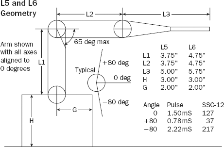
These dimensions are defined in SimulatedLynxL6Arm.cs at the top of the SimulatedLynxL6Arm class definition. Notice that this entity subclasses the SingleShapeEntity. This is because the arm entity itself only includes a single shape, which is the base of the arm. Each of the other segments in the arm is a separate entity joined to another entity in the arm as a child. This makes it easy to use the built-in ParentJoint that belongs to each entity to join the entities together.
The following code defines the dimensions of each part of the arm:
static float InchesToMeters(float inches) { return (float)(inches * 0.0254); }

// physical attributes of the arm
static float L1 = InchesToMeters(4.75f);
static float L2 = InchesToMeters(4.75f);
static float Grip = InchesToMeters(2.5f);
static float L3 = InchesToMeters(5.75f)—Grip;
static float L4 = 0.03f;
static float H = InchesToMeters(3f);
static float G = InchesToMeters(2f);
static float L1Radius = InchesToMeters(0.7f);
static float L2Radius = InchesToMeters(0.7f);
static float L3Radius = InchesToMeters(0.7f);
static float GripRadius = InchesToMeters(0.2f);
Because the dimensions are given on the diagram in inches but the units used by the simulator are meters, a simple utility function is used to convert the units. H specifies the height of the base, and G is the radius. The L1 entity corresponds to the upper arm, and the L2 entity is the lower arm. In Figure 8-7, the L3 segment includes both the wrist and the grippers. The entity divides this into the L3 entity, which includes the wrist to just before the grippers; an L4 entity, used to make the wrist rotate; and the Grip entity, which is 2.5 inches long. The GripRadius refers to the radius of each part of the gripper.
In addition to the size of each segment, you need to define the joints that will be used to join the segments. The following class defines the characteristics of each joint, as well as some run-time properties of the joint such as the target position, the current position, and the current speed of motion:
// This class holds a description of each of the joints in the arm.
class JointDesc
{
    public string Name;
    public float Min;  // minimum allowable angle
    public float Max;  // maximum allowable angle
    public PhysicsJoint Joint; // Phyics Joint
    public PhysicsJoint Joint2; // Alternate Physics Joint (used for gripper)
    public float Target;  // Target joint position
    public float Current;  // Current joint position
    public float Speed;  // Rate of moving toward the target position
    public JointDesc(string name, float min, float max)
    {
        Name = name; Min = min; Max = max;
        Joint = null;
        Joint2 = null;
        Current = Target = 0;
        Speed = 30;
    }

    // Returns true if the specified target is within the valid bounds
    public bool ValidTarget(float target)
    {
        return ((target >= Min) && (target <= Max));
    }

    // Returns true if the joint is not yet at the target position
    public bool NeedToMove(float epsilon)
    {
        if (Joint == null) return false;
        return (Math.Abs(Target—Current) > epsilon);
    }

    // Takes one step toward the target position based on the specified time
    public void UpdateCurrent(double time)
    {
        float delta = (float)(time * Speed);
        if (Target > Current)
            Current = Math.Min(Current + delta, Target);
        else
            Current = Math.Max(Current—delta, Target);
    }
}
The initialized properties of each joint are the name and the minimum and maximum angles that the joint supports. In the case of the grippers, you will be using linear joints, and the minimum and maximum values represent distances. ValidTarget provides a simple way to check a target joint position to determine whether it falls within the minimum and maximum for the joint. NeedToMove indicates whether the current joint position is within a certain distance of the target position. UpdateCurrent calculates a new Current position based on the speed of movement and the time that has elapsed.
The joints for the arm are defined in an array of descriptors as follows:
// Initialize an array of descriptions for each joint in the arm
JointDesc[] _joints = new JointDesc[]
{
    new JointDesc("Base", −180, 180),
    new JointDesc("Shoulder", −90, 90),
    new JointDesc("Elbow", −65, 115),
    new JointDesc("Wrist", −90, 90),
    new JointDesc("WristRotate", −90, 90),
    new JointDesc("Gripper", 0, InchesToMeters(2))
};
Notice that the minimum and maximum for the elbow joint are a little unusual due to the physical constraints of the arm, and the minimum and maximum for the gripper joint are 0 inches and 2 inches, respectively. The gripper is actually modeled using two simulated joints, one for each of the parts of the gripper. From a logical standpoint, though, the gripper position is treated as a single joint that specifies the distance between the left and right gripper.
The segment dimensions and the joint descriptions are used in the initialization constructor to programmatically build the arm entity. In the SimulatedLynxL6Arm constructor, one of the first things you'll notice is that the physics shape for the base is not quite as tall as the actual base. This arises from a design decision to only enable one degree of freedom per joint. The point where the upper arm attaches to the base could be thought of as having two degrees of freedom: the base rotation and the shoulder joint swivel. Instead, we have defined another entity called L0Entity between the base and the L1Entity. The ParentJoint of the L0Entity is used for the base rotation, and the ParentJoint of the L1Entity is used for the shoulder joint. The height of the base is lowered to prevent the L1Entity from colliding with the base when the shoulder joint is moved.
The base state and its shape are initialized with the following code:
// The physics shape for the base is slightly lower than the actual base
// so that the upper-arm segment does not intersect it as it moves around.
float baseHeight = H—L1Radius—0.001f;
State.Name = name;
State.Pose.Position = position;
State.Pose.Orientation = new Quaternion(0, 0, 0, 1);
State.Assets.Mesh = "L6_Base.obj";
MeshTranslation = new Vector3(0, 0.026f, 0);

// build the base
BoxShape = new BoxShape(new BoxShapeProperties(
    "Base",
    150, // mass
    new Pose(new Vector3(0, baseHeight / 2, 0), new Quaternion(0, 0, 0, 1)),
    new Vector3(G * 2, baseHeight, G * 2)));
Notice that the shape is a box, rather than a cylinder. The only way to specify a cylinder shape in the AGEIA engine is to use a mesh that is shaped like a cylinder with a SimplifiedConvexMeshEnvironmentEntity. The box is simpler and works fine.
In the spirit of full disclosure, it should be mentioned that there has been no attempt to specify accurate masses for each of the arm components. A mass of 150 Kg has been specified for the base, which is not accurate. If you wish to attach this arm to another entity in the environment, you will want to specify more accurate mass values to each entity in the arm. It is possible to make the base of the arm move as a result of the inertia of swinging the upper part of the arm quickly. The base of the arm can be made immobile by making it kinematic using the following:
State.Flags |= EntitySimulationModifiers.Kinematic;
The default pose specified for the box places it baseHeight/2 above the shape origin. This puts the origin of the base entity on the ground instead of baseHeight/2 above the ground, making it easier to position within the world. We set a value on the MeshTranslation property of the base entity, moving the mesh associated with the base up to correspond with the position of the shape.
The next part of the arm to be defined is the L0Entity. All of the remaining entities in the arm are SingleShapeSegmentEntities. As you will recall from the TestBench application earlier in this chapter, this type of entity allows its ParentJoint to be overridden. The L0Entity contains a single sphere shape, whose radius is the same as the L1Entity. The ParentJoint of this entity controls the rotation of the base. It is created as shown here:
// build and position L0 (top of the base)
SphereShape L0Sphere = new SphereShape(new SphereShapeProperties(
    "L0Sphere",
    50,
    new Pose(new Vector3(0, 0, 0), new Quaternion(0, 0, 0, 1)),
    L1Radius));

SingleShapeSegmentEntity L0Entity =
    new SingleShapeSegmentEntity(L0Sphere, position + new Vector3(0, H, 0));
L0Entity.State.Pose.Orientation = new Quaternion(0, 0, 0, 1);
L0Entity.State.Name = name + "_L0";
L0Entity.State.Assets.Mesh = "L6_L0.obj";
L0Entity.MeshTranslation = new Vector3(0, −0.02f, 0);
JointAngularProperties L0Angular = new JointAngularProperties();
L0Angular.Swing1Mode = JointDOFMode.Free;
L0Angular.SwingDrive = new JointDriveProperties(JointDriveMode.Position,
    new SpringProperties(50000000, 1000, 0), 100000000);
EntityJointConnector[] L0Connectors = new EntityJointConnector[2]
{
    new EntityJointConnector(L0Entity,
        new Vector3(0,1,0), new Vector3(1,0,0), new Vector3(0, 0, 0)),
    new EntityJointConnector(this,
        new Vector3(0,1,0), new Vector3(1,0,0), new Vector3(0, H, 0))
};
L0Entity.CustomJoint = new Joint();
L0Entity.CustomJoint.State = new JointProperties(L0Angular, L0Connectors);
L0Entity.CustomJoint.State.Name = "BaseJoint";

this.InsertEntityGlobal(L0Entity);
The L0Entity contains a single sphere. Its center is positioned H meters above the ground so that its center corresponds to the base's center of rotation. It is important that the initial position of the base and L0Entity is very close to their position once they are connected with a joint. If the initial position is different, then the pieces will snap together violently during the first frame of the simulation and the arm will likely topple over. A joint is defined with the Swing1 degree of freedom unlocked so that the joint will rotate freely around the Y axis. The L0Entity is inserted as a child of the base entity using the InsertEntityGlobal method because the position of the L0Entity is defined in world coordinates, rather than coordinates relative to the base entity.
After all that work, you end up with the physics model shown in Figure 8-8.
It's not very impressive yet but it gets better. Next, you attach the upper arm segment (L1Entity) to the L0Entity:
// build and position L1 (upper arm)
CapsuleShape L1Capsule = new CapsuleShape(new CapsuleShapeProperties(
   "L1Capsule",
    2,
    new Pose(new Vector3(0, 0, 0), new Quaternion(0, 0, 0, 1)),
    L1Radius,
    L1));

SingleShapeSegmentEntity L1Entity =
    new SingleShapeSegmentEntity(L1Capsule, position + new Vector3(0, H, 0));
L1Entity.State.Pose.Orientation = new Quaternion(0, 0, 0, 1);
L1Entity.State.Name = name + "_L1";
L1Entity.State.Assets.Mesh = "L6_L1.obj";
JointAngularProperties L1Angular = new JointAngularProperties();
L1Angular.TwistMode = JointDOFMode.Free;
L1Angular.TwistDrive = new JointDriveProperties(JointDriveMode.Position,
new SpringProperties(50000000, 1000, 0), 100000000);
EntityJointConnector[] L1Connectors = new EntityJointConnector[2]
{
new EntityJointConnector(L1Entity,
new Vector3(0,1,0), new Vector3(0,0,1), new Vector3(0, -L1/2, 0)),
new EntityJointConnector(L0Entity,
new Vector3(0,1,0), new Vector3(0,0,1), new Vector3(0, 0, 0))
};
L1Entity.CustomJoint = new Joint();
L1Entity.CustomJoint.State = new JointProperties(L1Angular, L1Connectors);
L1Entity.CustomJoint.State.Name = "Shoulder|-80|80|";
L0Entity.InsertEntityGlobal(L1Entity);This is much like the code that was used to define the L0Entity except that you are now using a capsule shape for the segment. The entity is positioned exactly H meters above the ground so that its rounded end-cap coincides with the sphere in the L0Entity. Its center of rotation will correspond to the center of the L0Entity sphere.
When the joint position is specified for the L1Entity in L1Connects[0], a position of (0, -L1/2, 0) is specified for the joint position for which this coordinate is relative to the L1Entity. A position of (0,0,0) is specified for the L0Entity because this joint will be located exactly at the sphere's center. When the joint is created, these two points on the two entities will be constrained to be in the same place. Notice that the name you give to the joint includes a minimum and maximum value that the JointMover service uses to scale its controls, as in the TestBench sample described previously.
Finally, the L1Entity is added as a child of the L0Entity and another segment of the arm is attached.
The L2Entity is created and joined to the L1Entity in much the same way. The only difference lies in the joint connectors, which are defined as follows:
EntityJointConnector[] L2Connectors = new EntityJointConnector[2]
{
    new EntityJointConnector(L2Entity,
        new Vector3(1,0,0), new Vector3(0,0,1), new Vector3(0, -L2/2, 0)),
    new EntityJointConnector(L1Entity,
        new Vector3(0,1,0), new Vector3(0,0,1), new Vector3(0, L1/2, 0))
};
Notice that the normal vector specified for the L2Entity connector is (1,0,0) and the normal vector specified for the L1Entity connector is (0,1,0). This joins the entities at right angles to each other.
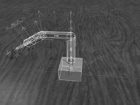
The L3Entity and L4Entity are created and joined in much the same way. At this point the physical model looks like Figure 8-9.
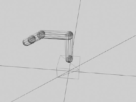
It is shown in wireframe view with the wrist joint slightly bent to better demonstrate how the entities are connected. The sphere in the middle of the wrist segment is really the end-caps of the L3Entity and the L4Entity.
All that remains is to add the two gripper entities. The gripper is modeled as two capsules that move together and apart using linear joints. Although each part of the gripper is joined to the L4Entity with its own joint, the gripper is treated logically as if it has one joint. The following code adds the left gripper to the entity:
// build and position LeftGrip
CapsuleShape LeftGripCapsule = new CapsuleShape(new CapsuleShapeProperties(
    "LeftGripCapsule",
    1f,
    new Pose(new Vector3(0, 0, 0), new Quaternion(0, 0, 0, 1)),
    GripRadius,
    Grip));
LeftGripCapsule.State.DiffuseColor = new Vector4(0, 0, 0, 1);

LeftGripEntity = new SingleShapeSegmentEntity(
    LeftGripCapsule, position + new Vector3(0, H, 0));
// position the entity close to its final position once the joint is connected
LeftGripEntity.Position = new xna.Vector3(-0.24f, 0.19f, 0.01f);
LeftGripEntity.Rotation = new xna.Vector3(179.94f, −176.91f, 89.67f);
LeftGripEntity.State.Name = name + "_LeftGrip";
// use a linear joint for the left grip
JointLinearProperties LeftGripLinear = new JointLinearProperties();
LeftGripLinear.XMotionMode = JointDOFMode.Free;
LeftGripLinear.XDrive = new JointDriveProperties(JointDriveMode.Position,
    new SpringProperties(5000000000, 1000, 0), 100000000);
EntityJointConnector[] LeftGripConnectors = new EntityJointConnector[2]
{
new EntityJointConnector(LeftGripEntity,
new Vector3(1,0,0), new Vector3(0,0,1), new Vector3(0, -Grip/2, 0)),
new EntityJointConnector(L4Entity,
new Vector3(1,0,0), new Vector3(0,0,1), new Vector3(0, L4/2, GripRadius))
};
LeftGripEntity.CustomJoint = new Joint();
LeftGripEntity.CustomJoint.State =
new JointProperties(LeftGripLinear, LeftGripConnectors);
LeftGripEntity.CustomJoint.State.Name = "LeftGripJoint|-0.0254|0|";
L4Entity.InsertEntityGlobal(LeftGripEntity);The main difference from the other joints is that this is a linear joint. The X degree of freedom is unlocked. The range of the gripper is 0 to 2 inches, so the range of this single half of the gripper is 0 to 1 inch. One other difference is that a DiffuseColor is specified for the capsule shape in this entity. This is because there is no custom mesh specified for this entity. The default capsule shape, colored dark black, is used for the visual representation. With the grippers added, the complete physics model looks like the image shown in Figure 8-10.
Finally, a camera entity is mounted just above the L4Entity so that you can get a close-up view of what the arm is manipulating:
// Add a camera to see what the gripper is gripping
AttachedCameraEntity gripCam = new AttachedCameraEntity();
gripCam.State.Name = "Arm Cam";

// move the camera above the L4entity and look at the grippers
gripCam.State.Pose = new Pose(new Vector3(0.05f, −0.01f, 0),
    Quaternion.FromAxisAngle(0, 1, 0, (float)(Math.PI / 2)) *
    Quaternion.FromAxisAngle(1, 0, 0, (float)(Math.PI / 3)));

// adjust the near plane so that we can see the grippers
gripCam.Near = 0.01f;

// the gripcam coordinates are relative to the L4Entity, don't use InsertEntityGlobal
L4Entity.InsertEntity(gripCam);
The position and orientation of the camera is defined relative to the L4Entity, and InsertEntity is used rather than InsertEntityGlobal. Another interesting thing to note is that the near plane of the camera is adjusted to be 1 centimeter. All objects closer to the camera than the near plane are not displayed. The default value for the near plane is 10 centimeters, which clips the grippers from the scene. A closer near plane allows the camera to get closer to objects in the scene at the cost of reducing the depth buffer resolution for the scene. In some extreme circumstances, this can cause occlusion problems with some objects in the scene unless the far plane is brought in by the same factor as the near plane.
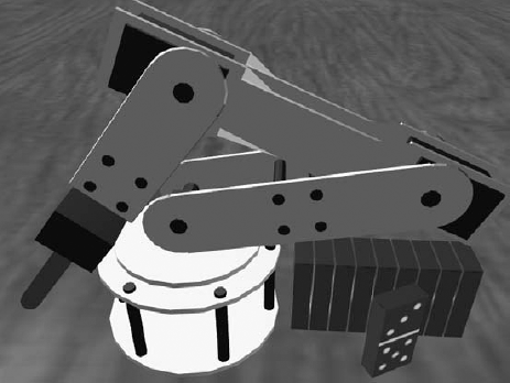
The physics model is perfectly adequate to model the motion and physical constraints of the arm, but it is pretty uninteresting visually. A few custom meshes make quite a difference to the simulation, as shown in Figure 8-11.
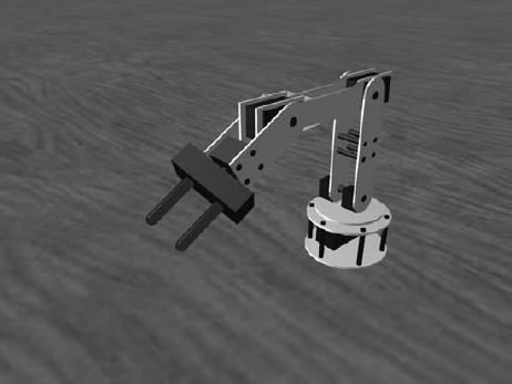
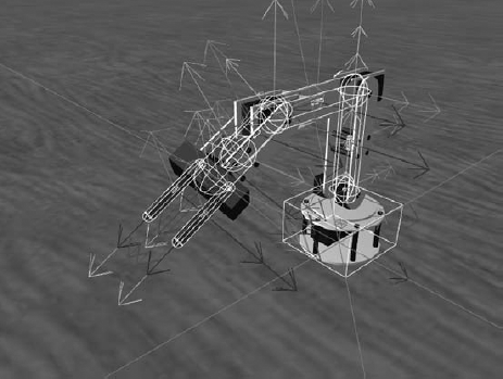
The custom meshes were modeled in Maya. The six Maya files for the models are included in the ProMRDSmayamodels directory starting with l6_base.ma and ending with l6_l4.ma. Corresponding .obj and .mtl files are included in the storemedia directory for use by the simulator. The combined physics and visual view of the arm model is shown in Figure 8-12.
This is a good time to run the arm simulation and to manipulate the joints to get a feel for the range and capabilities of the arm. You can easily run the arm simulation from the command line using the provided .cmd file as follows:
C:Microsoft Robotics Studio (1.5)>SimulatedLynxL6ArmThis starts a DSS node with the Lynx.L6Arm.Simulation manifest. This manifest runs the SimulatedLynxL6Arm service along with the JointMover service. You can use the JointMoverService to manipulate the arm joints and move the arm around. The SimulatedLynxL6Arm user interface is explained in a later section.
The SimulatedLynxL6ArmEntity defines a MoveTo method that can be used to move the arm to a specific position. The method takes the following parameters, which completely specify the arm position:
Parameter | Units | Description |
|---|---|---|
Degrees | Rotation angle of the base joint | |
Degrees | ||
Degrees | ||
Degrees | Pivot angle of the wrist joint | |
Degrees | Rotation angle of the wrist joint | |
Meters | Distance of separation between the grippers | |
| Seconds | Time to complete the motion |
This method returns a SuccessFailurePort after the motion has been initiated. A Success message is posted to the port when the motion successfully completes. Otherwise, an Exception message is posted if an error was encountered.
The arm entity has a private Boolean variable called _moveToActive that indicates whether a move operation is currently underway. If a call is made to MoveTo while a move operation is currently active, an exception message is posted to the response port.
Each parameter is checked against the bounds specified in the corresponding joint description. An invalid parameter results in an exception being posted to the response port, with a message indicating which parameter was bad:
SuccessFailurePort responsePort = new SuccessFailurePort();

if (_moveToActive)
{
    responsePort.Post(new Exception("Previous MoveTo still active."));
    return responsePort;
}

// check bounds.  If the target is invalid, post an exception message
// to the response port with a helpful error.
if(!_joints[0].ValidTarget(baseVal))
{
    responsePort.Post(new Exception(
        _joints[0].Name + "Joint set to invalid value: " + baseVal.ToString()));
    return responsePort;
}
After all of the parameters have been validated, each joint description Target value is set to the specified value. In addition, a speed value is calculated for each joint based on the distance between the current value and the target value and the overall time specified for completion of the motion. Each joint gets its own speed value to ensure that joints that have a large distance to move will move more quickly than joints that have a small distance to move so that all joints complete their motion at the same time:
// set the target values on the joint descriptors
_joints[0].Target = baseVal;
_joints[1].Target = shoulderVal;
_joints[2].Target = elbowVal;
_joints[3].Target = wristVal;
_joints[4].Target = rotateVal;
_joints[5].Target = gripperVal;

// calculate a speed value for each joint that will cause it to complete
// its motion in the specified time
for(int i=0; i<6; i++)
    _joints[i].Speed = Math.Abs(_joints[i].Target—_joints[i].Current) / time;
The MoveTo method then sets the _moveToActive flag to true and returns the response port. As you can see, the motion is set up in this method but the joint is actually not moved until its update method is called.
The entity's Update method is called once each frame, ideally about 60 times per second. Each time this method is called, the joint is moved a small amount based on how much time has elapsed since the last update.
The first time Update is called after the entity is initialized, it sets references to the newly created joints in the joint description array. It then follows the pattern shown in the following code to update each joint:
// update joints if necessary
if (_moveToActive)
{
    bool done = true;
    // Check each joint and update it if necessary.
    if (_joints[0].NeedToMove(_epsilon))
    {
        done = false;

        Vector3 normal = _joints[0].Joint.State.Connectors[0].JointNormal;
        _joints[0].UpdateCurrent(_prevTime);
        _joints[0].Joint.SetAngularDriveOrientation(
            Quaternion.FromAxisAngle(
                normal.X, normal.Y, normal.Z,
                DegreesToRadians(_joints[0].Current)));
    }
If a motion sequence is currently active, then each joint is evaluated to determine whether it still needs to be moved to hit its target value. If NeedToMove returns true, then UpdateCurrent is called to move the joint toward its target in a step that depends on the speed of the current movement and the amount of time that has elapsed since the last time Update was called. A new joint orientation is calculated from the new joint position and the joint is set to its new position.
If none of the joints need to be updated, then the motion sequence is finished. _moveToActive is set to false and a new SuccessResult message is posted to the response port.
This is a better way of controlling joint movement than the Simulation Tutorial 4 provided in the SDK, which relies on the damping coefficient of the joint drive to dictate the speed at which the joint moves. The method illustrated in this example provides much more control over the joint's rate of speed and allows for the possibility of setting a maximum motor movement speed according to the characteristics of the physical motors on the arm.
At this point, you have a great arm model that closely simulates the capabilities of the real arm. Unfortunately, the AGEIA physics engine appears to have a limitation that significantly affects this arm model. Although the gripper joints bring the grippers together and it is possible to close them on an object, the physics engine does not do a good job of simulating the friction between the grippers and the grasped object. Even with a high-friction material specified for the object and the grippers, the arm cannot pick up an object without it sliding away from the grippers. What do you do when the physics engine won't work properly? You cheat!
Because an arm really isn't very interesting if it is not able to pick up objects, you will define code that detects when the arm is closing on an object. A joint will be created on-the-fly to attach the object to the grippers, and then that object will follow the grippers as they move—just as if it had been grasped. You'll see how this works in detail because it provides a good example of using some additional simulator functionality.
Look at the following lines of code near the bottom of the MoveTo function that was described in the section "Moving the Arm":
if((_joints[5].Target > gripperVal) && (Payload == null))
{
    _attachPayload = true;
}
else if ((_joints[5].Target < gripperVal) && (Payload != null))
{
    _dropPayload = true;
}
_joints[5] represents the gripper joint. When the motion sequence is being set up, you detect whether the grippers are closing or opening. If they are closing, then you set _attachPayload to be true. If they are opening, then you set _dropPayload to be true. These flags are not used until the motion sequence is completed. This code is in the Update method:
// no joints needed to be updated, the movement is finished
if (_attachPayload)
{
    // we are attaching a payload object after the motion has completed
    if (_intersect == null)
    {
        // haven't yet cast the intersection ray, do it now
        _intersect = new IntersectRay(new Ray(Origin, Direction));
        SimulationEngine.GlobalInstancePort.Post(_intersect);
    }
    List<TriangleIntersectionRecord> results =
        _intersect.ResponsePort.Test<List<TriangleIntersectionRecord>>();

    if (results != null)
    {
        // we've received the intersection results,
        // see if we need to attach a payload
        AttachPayload(results);
        if (_payload != null)
        {
            // create a joint to hold the payload
            _payload.PhysicsEntity.UpdateState(false);
            L4Entity.PhysicsEntity.UpdateState(false);
            Vector3 jointLocation = TypeConversion.FromXNA(xna.Vector3.Transform(
                TypeConversion.ToXNA(_payload.State.Pose.Position),
                xna.Matrix.Invert(L4Entity.World)));

            Vector3 normal = new Vector3(0, 1, 0);
            Vector3 axis = new Vector3(1, 0, 0);

            // calculate a joint orientation that will preserve the orientation
            // relationship between L4Entity and the payload
            Vector3 parentNormal =
                Quaternion.Rotate(L4Entity.State.Pose.Orientation, normal);
            Vector3 parentAxis =
                Quaternion.Rotate(L4Entity.State.Pose.Orientation, axis);
Vector3 thisNormal =
Quaternion.Rotate(_payload.State.Pose.Orientation, normal);
Vector3 thisAxis =
Quaternion.Rotate(_payload.State.Pose.Orientation, axis);
EntityJointConnector[] payloadConnectors = new EntityJointConnector[2]
{
new EntityJointConnector(_payload,
thisNormal, thisAxis, new Vector3(0, 0, 0)),
new EntityJointConnector(L4Entity,
parentNormal, parentAxis, jointLocation)
};
_payloadJoint = PhysicsJoint.Create(
new JointProperties((JointAngularProperties)null,
payloadConnectors));
_payloadJoint.State.Name = "Payload Joint";
PhysicsEngine.InsertJoint(_payloadJoint);
// the payload is now fixed to the L4Entity
}
// the payload attach is complete
_attachPayload = false;
_intersect = null;
// the motion is also complete, send the completion message
_moveToActive = false;
_moveToResponsePort.Post(new SuccessResult());
}
}
// once a ray has been cast into the environment,
// this method interprets the results and
// sets a payload in _payload if one is found within the grippers
public void AttachPayload(List<TriangleIntersectionRecord> results)
{
foreach (TriangleIntersectionRecord candidate in results)
{
if (candidate.OwnerEntity.GetType() == typeof(SingleShapeSegmentEntity))
continue;
if (candidate.IntersectionDistance > Grip)
break;
_payload = candidate.OwnerEntity;
}
}If _attachPayload is set after the motion is completed, a ray is constructed that originates in the center of the L4Entity and extends in the direction of the grippers. The ray is intersected with all entities in the environment. If a valid entity is found, that entity is attached to the L4Entity with a joint.
The first time this code is executed, _intersect is null and a new ray is constructed and cast into the environment by posting an IntersectRay message on the SimulationEngine port. This is the first time you've seen this method. It calculates intersections with the visual mesh of an object. The laser range finder discussed in Chapter 6 uses the PhysicsEngine.Raycast2D method to cast a ray into the environment that intersects with physics shapes. You can use either method depending on whether you desire an intersection with the visual mesh or an intersection with the physics shapes.
Each subsequent time the Update method is called, the responseport of the IntersectRay message is checked for results. When the results are available, they are passed to the AttachPayload method, which determines whether any of the intersection results represent an object that should be attached to the arm. If so, _payload is set to the entity. If a valid payload is found, then a joint is built that attaches the payload entity to the L4Entity while maintaining its relative position and orientation.
Once the results have been processed, a message is sent on the MoveTo response port to indicate that the motion sequence has been completed.
That covers the sequence of events when the payload is grasped. When the grippers are opened and a payload entity is currently attached, the _dropPayload Boolean is set to true. If this flag is set at the end of the Update method, the joint that attaches the payload is deleted and the payload entity is no longer fixed to the arm.
What are the implications of this terrible hack? It means that the arm simulation does a poor job of modeling how well an object is grasped by the grippers. In fact, if an object is within the grippers and they are closed even slightly, the object will be picked up. In the real world, the arm can only pick up objects if the grippers are set to an appropriate value for the size of the object. In addition, once the simulation arm grips an object, the object is firmly attached until it is released. With a real arm, moving the arm too fast may cause the object to dislodge from the grippers. These limitations should be taken into account when using the simulated arm to simulate algorithms intended for a real arm.
Technically, you have everything you need at this point to move the arm around, but it isn't much fun to maneuver the arm to pick up an object by specifying each of the joint angles. It is much more convenient to simply specify the X,Y, Z coordinates of the grippers and their rotation and angle of approach, enabling the arm to move to that configuration. The process of calculating the joint angles from such a high-level specification is called inverse kinematics. The reverse process, calculating the gripper position from the joint angles, is called forward kinematics.
There are three solutions for the inverse kinematics for the Lynx 6 robotic arm, available on the Lynxmotion website at the following URLs:
www.lynxmotion.com/images/html/proj073.htm
www.lynxmotion.com/images/html/proj057.htm
www.lynxmotion.com/images/html/proj058.htm
The SimulatedLynxL6Arm service described in this chapter uses an inverse kinematics solution similar to the third link. The service implements a method called MoveToPosition that takes the parameters in the following table, calculates the joint positions, and then calls MoveTo on the arm entity to execute the motion:
Units | Description | |
|---|---|---|
X | Meters | |
Y | Meters | |
Z | Meters | |
P | Degrees | Angle of approach of the gripper (−90 is vertical with the gripper down) |
W | Degrees | |
Grip | Meters | Distance of separation between the grippers |
Time | Seconds | Amount of time to complete the motion |
The code is fairly straightforward even if the math isn't:
// This method calculates the joint angles necessary to place the arm into the
// specified position.  The arm position is specified by the X,Y,Z coordinates
// of the gripper tip as well as the angle of the grip, the rotation of the grip,
// and the open distance of the grip.  The motion is completed in the
// specified time.
public SuccessFailurePort MoveToPosition(
    float x, // x position
    float y, // y position
    float z, // z position
    float p, // angle of the grip
    float w, // rotation of the grip
    float grip, // distance the grip is open
    float time) // time to complete the movement
{
    // taken from Hoon Hong's ik2.xls IK method posted on the Lynx website

    // physical attributes of the arm
    float L1 = InchesToMeters(4.75f);
    float L2 = InchesToMeters(4.75f);
    float Grip = InchesToMeters(2.5f);
    float L3 = InchesToMeters(5.75f);
    float H = InchesToMeters(3f);  // height of the base
    float G = InchesToMeters(2f);  // radius of the base

    float r = (float)Math.Sqrt(x * x + z * z); // horizontal distance to the target
    float baseAngle = (float)Math.Atan2(-z, -x); // angle to the target

    float pRad = DegreesToRadians(p);
    float rb = (float)((r—L3 * Math.Cos(pRad)) / (2 * L1));
    float yb = (float)((y—H—L3 * Math.Sin(pRad)) / (2 * L1));
    float q = (float)(Math.Sqrt(1 / (rb * rb + yb * yb)—1));
    float p1 = (float)(Math.Atan2(yb + q * rb, rb—q * yb));
    float p2 = (float)(Math.Atan2(yb—q * rb, rb + q * yb));
    float shoulder = p1—DegreesToRadians(90);  // angle of the shoulder joint
float elbow = p2—shoulder; // angle of the elbow joint
float wrist = pRad—p2; // angle of the wrist joint
// Position the arm with the calculated joint angles.
return _l6Arm.MoveTo(
RadiansToDegrees(baseAngle),
RadiansToDegrees(shoulder),
RadiansToDegrees(elbow),
RadiansToDegrees(wrist),
w,
grip,
time);
}The X and Z coordinates are converted to a radius and an angle (cylindrical coordinates). The angle of approach (p) of the gripper, along with the radius and elevation (Y coordinate), is used to calculate joint angles from the gripper back to the base. The radian joint values are converted back to degrees and passed to the MoveTo method.
It is not possible for the arm to accommodate all combinations of gripper coordinates and angle-of-approach values. If an impossible position is requested, one of the joint angles will be out of bounds and the MoveTo method will post an exception message to the response port.
The SimulatedLynxL6Arm service implements a Windows Forms user interface using the same principles described in Chapter 7. The window is shown in Figure 8-13.
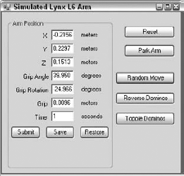
The seven parameters to the MoveToPosition method appear in this dialog. You can enter values using meters for distance parameters, degrees for angle parameters, and seconds for the time parameters. After the Submit button is pressed, the arm moves to the requested position if it is valid. Otherwise, an error message is displayed if the position is invalid.
Just to make things more interesting, 10 dominos have been added to the scene. These dominos are SingleShapeEntities consisting of a single box shape. Their visual mesh provides a texture map for each face to make them more interesting.
Pressing the Reset button causes the currently executing motion sequence to stop, resetting the position of the dominos and the arm to their initial position using the following code:
// Place the dominos back in their initial positions
public void ResetDominos()
{
    for (int i = 0; i < DominoCount; i++)
    {
        Dominos[i].State.Pose = new Pose(InitialDominoPosition(i));
        // Don't move the domino until its Update method is executing
        Dominos[i].DeferredTaskQueue.Post(new Task<int>(i, DeferredSetDominoPose));
    }
}

// Restore the arm to its initial position
public void ResetArmPosition()
{
    _l6Arm.State.Pose = new Pose(new Vector3(0, 0, 0));
    // Don't set the pose until the Update method executes
    _l6Arm.DeferredTaskQueue.Post(new Task(DeferredSetArmPose));
    // wait for the arm motion to settle before making it non-kinematic
    Activate(Arbiter.Receive(false, TimeoutPort(500), delegate(DateTime now)
    {
        _l6Arm.DeferredTaskQueue.Post(new Task(ReleaseArm));
    }));
}

// Returns the initial position of the requested domino
Vector3 InitialDominoPosition(int i)
{
    return new Vector3(InchesToMeters(2.5f) + i * 0.011f, 0, 0);
}

// Create and place DominoCount dominos
public IEnumerator<ITask> CreateDominos()
{
    for(int i=0; i<DominoCount; i++)
    {
        Dominos[i] = new Domino(InitialDominoPosition(i), i);
        SimulationEngine.GlobalInstancePort.Insert(Dominos[i]);
    }

    yield break;
}

// This method sets the pose of a domino in its update method
void DeferredSetDominoPose(int i)
{
Dominos[i].PhysicsEntity.SetPose(Dominos[i].State.Pose);
}
// Sets the arm pose in its update method
void DeferredSetArmPose()
{
_l6Arm.PhysicsEntity.IsKinematic = true;
_l6Arm.PhysicsEntity.SetPose(_l6Arm.State.Pose);
}
// Restores the arm to non-kinematic
void ReleaseArm()
{
_l6Arm.PhysicsEntity.IsKinematic = false;
}Notice that the dominos are moved back to their original positions by posting a task to each of their deferred task queues. The task will execute during their Update method when it is safe to call PhysicsEntity.SetPose to move them.
It is similar for the arm except you must also deal with the inertia of the arm. When the arm entity is moved quickly, its segments act like a pendulum, storing the inertia, and the physics engine causes the arm to continue moving during the next few frames. You can prevent this effect by setting the base of the arm as kinematic before you move it. After it is moved, the code waits for half a second before setting the arm back to its non-kinematic state.
Pressing the Park Arm button executes two calls to MoveTo as shown in the following code:
// This method puts the arm into its parked position
public IEnumerator<ITask> ParkArm()
{
    // Raise the grippers away from the working surface
    yield return Arbiter.Choice(_l6Arm.MoveTo(0, 0, 80, 0, 0, 0.05f, 2),
        delegate(SuccessResult s) { },
        ShowError);

    // Move to the parked position
    yield return Arbiter.Choice(_l6Arm.MoveTo(0, 80, −56, −75.2f, 0, 0.05f, 3),
        delegate(SuccessResult s) { },
        ShowError);
}
The sequence of events in this code snippet is as follows:
The first call to
_l6Arm.MoveTois executed and returns a response port.Arbiter.Choicereturns a task that executes when a response message is posted to the response port.The first delegate executes if the response message was a
SuccessResult. Otherwise, the second delegate executes and prints the error information to the console.The second call to
_l6Arm.MoveTois executed and returns a response port.Arbiter.Choicereturns a task that executes when a response message is posted to the response port.Finally, the first delegate executes if the response message was a
SuccessResultor the error message is printed.
Stacking yield return statements in an iterator method like this guarantees that the arm motions will be executed one after another in the proper order with no wasteful spin-waiting on the CPU.
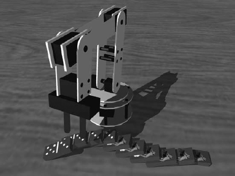
The first MoveTo command raises the gripper nearly vertical, and the second one puts it into the parked position shown in Figure 8-14.
Clicking the Random Move button causes the arm to be moved to a random position. Random values for each of the parameters are chosen without regard to what is valid and then passed to MoveToPosition. This continues until MoveToPosition returns a SuccessResult, meaning the position specified was valid. Whenever MoveToPosition is called, the parameters on the Winforms window are updated.
Both the Reverse Dominos button and the Topple Dominos button execute a sequence of arm moves. The first sequence causes the arm to pick up the dominos one by one and put them back down again on the other side of the arm. The Topple Dominos button causes the arm to pick up the dominos one by one and lay them out in a pattern. The dominos are then knocked down in classic fashion. The code for the Topple Dominos motion is shown here:
// This method executes a series of arm movements that cause the arm to pick up
// dominos from one side and put them down in a pattern on the other side and
// then the arm causes the dominos to fall.
public IEnumerator<ITask> ToppleDominos()
{
    _moveSequenceActive = true;
    for (int i = 0; i < DominoCount; i++)
    {
        Vector3 src = InitialDominoPosition(DominoCount—i—1);

        // move the arm into position to grasp the domino
        yield return CheckAndMove(0.18f, 0.06f, src.Z, −80, 0, 0.04f, 3);
        yield return CheckAndMove(src.X, 0.025f, src.Z, −90, 0, 0.04f, 1f);
        // close the grip to grab the domino
        yield return CheckAndMove(src.X, 0.025f, src.Z, −90, 0, 0.025f, 0.5f);
        // move it out and up
        yield return CheckAndMove(0.17f, 0.2f, src.Z, 0, 0, 0.025f, 1);
        // move it to the other side

        Vector3 dst = ToppleDominoPosition[i];
        yield return CheckAndMove(dst.X—0.02f, 0.2f, dst.Z, 0, 0, 0.025f, 2);
        // move it into position
        yield return CheckAndMove(dst.X—0.02f, 0.03f, dst.Z, −90,
            AdjustWrist(0, dst.X, dst.Z), 0.025f, 1);
        yield return CheckAndMove(dst.X, 0.03f, dst.Z, −90,
            AdjustWrist(0, dst.X, dst.Z), 0.025f, 0.5f);
        // lower it
        yield return CheckAndMove(dst.X, 0.026f, dst.Z, −90,
            AdjustWrist(0, dst.X, dst.Z), 0.025f, 1);
        // release it
        yield return CheckAndMove(dst.X, 0.026f, dst.Z, −90,
            AdjustWrist(0, dst.X, dst.Z), 0.04f, 0.5f);
        // back away
        yield return CheckAndMove(dst.X, 0.06f, dst.Z, −80,
            AdjustWrist(0, dst.X, dst.Z), 0.04f, 1);
    }

    // knock them down
    Vector3 final = ToppleDominoPosition[9];    // the last domino position
    yield return CheckAndMove(final.X, 0.05f, final.Z—0.04f, −80, 0, 0, 1);
    yield return CheckAndMove(final.X, 0.05f, final.Z—0.04f, −80, 0, 0, 0.5f);

    // pause for dramatic effect
    yield return Arbiter.Receive(false, TimeoutPort(500), delegate(DateTime now)
        { });
    yield return CheckAndMove(final.X, 0.05f, final.Z + 0.06f, −80, 0, 0, 0.3f);
    yield break;
}

// This method calculates the wrist rotation angle that will orient the wrist to
// the specified angle relative to the X axis.
float AdjustWrist(float angle, float x, float z)
{
float val = angle + RadiansToDegrees((float)(Math.Atan2(-z, -x))) + 90;
while (val < −90)
val += 180;
while (val > 90)
val -= 180;
return val;
}
// check for early termination of the motion and call MoveToPosition
ITask CheckAndMove(
float x, float y, float z, float gripAngle,
float gripRotation, float grip, float time)
{
if (_moveSequenceActive)
{
return Arbiter.Choice(
MoveToPosition(x, y, z, gripAngle, gripRotation, grip, time),
delegate(SuccessResult s) { },
ShowError);
}
else
{
return new Task(DoNothing);
}
}
void DoNothing()
{
}
// The destination positions for the dominos in the topple movement
Vector3[] ToppleDominoPosition = new Vector3[]
{
new Vector3(-0.11f,0,0.125f),
new Vector3(-0.12f,0,0.10f),
new Vector3(-0.125f,0,0.075f),
new Vector3(-0.12f,0,0.05f),
new Vector3(-0.11f,0,0.025f),
new Vector3(-0.10f,0,0.00f),
new Vector3(-0.095f,0,-0.025f),
new Vector3(-0.10f,0,-0.05f),
new Vector3(-0.11f,0,-0.075f),
new Vector3(-0.12f,0,-0.10f)
};The CheckAndMove method ensures that the sequence is still active. If the Reset button is clicked, _moveSequenceActive becomes false and a null task is returned instead of the MoveToPosition task. The ToppleDominoPosition array specifies where the arm will place each domino (see Figure 8-15).
Look at the calls to the AdjustWrist method. This method calculates the angle that the gripper will make relative to the X axis and then adjusts that angle by rotating the wrist so that the domino is placed at the specified angle.
Have some fun putting the arm through its paces. You can change the pattern of the dominos by editing the ToppleDominoPosition array or you can define entirely new motion sequences. As you debug a new motion sequence, watch the console output for messages indicating that a requested motion is invalid or set a breakpoint on the ShowError method.
This chapter explored the world of joints and articulated entities. You learned how to join two entities together with a joint and became familiar with the many properties of a joint. The TestBench sample service provided a way to examine the behavior of different joint types and to prototype new joints.
The SimulatedLynxL6Arm service showed how to build a robotic arm entity with six degrees of freedom. The arm service included a user interface and inverse kinematics code that made it easy to define new motion sequences for the arm to perform.
Chapter 9 includes additional examples of articulated entities in the simulation environment.