
The Microsoft Visual Programming Language (VPL) is a new application development environment designed specifically to work with DSS services. Programs are defined graphically in data flow diagrams rather than the typical sequence of commands and instructions found in other programming languages. VPL provides an easy way to quickly define how data flows between services. It is useful for beginning programmers because they can quickly specify their intent, but it is also well suited to help with prototyping and code generation for more experienced programmers. It is also useful for specifying robotic orchestration services within the context of the Microsoft Robotics Developer Studio SDK, but it can be used outside of robotics as well.
This chapter covers what it means to work with a data flow language, how to specify a data flow diagram using the basic activities provided by VPL, and how to debug and run it. You won't find any robots in this chapter but you will learn how to use VPL to control robots in Chapter 11.
Many people learn how to program using an imperative language such as BASIC or C++. Such a language uses control statements to modify program state. This matches the underlying hardware implementation of the CPU well because it is built to execute machine code statements that modify memory.
When a program is data- or event-driven and has different parts that execute asynchronously, the imperative programming model can become inefficient and difficult to use. The following example shows why this might sometimes be true.
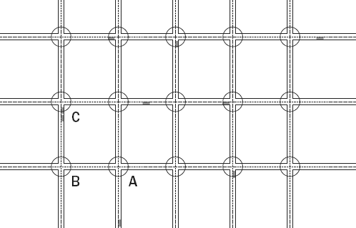
Imagine a program as a city grid. Each intersection represents some processing that must be done, and cars on the roads between intersections represent data, as shown in Figure 10-1.
A typical imperative program might take the following form:
For each intersection
    While not enough cars are waiting
        Sleep for a time.
    Do some calculations and call the next intersection routine with the results
The calculations done at each intersection can be arbitrarily complex and may depend on the state of multiple cars waiting at the intersection. This approach can lead to inefficiency because the instructions associated with each intersection must periodically run to determine whether enough cars are waiting. In addition, because cars may arrive at each intersection at an arbitrary time, race conditions can arise if the processing instructions at each intersection are not carefully defined.
In a data flow language, the emphasis is on following the cars rather than processing the intersections. A data flow diagram for the city example above would look much like the city grid, with the roads representing data connections and the intersections representing processing activities. None of the intersection code runs until it is presented with data.
Let's say that data enters the diagram at the bottom and approaches intersection A. The code for intersection A runs to process the data and puts the resulting state on the way to intersection B. The code for intersection B then runs and sends the modified state to intersection C. Intersection C is programmed to wait until data is available on at least two of its roads before passing the resulting data off to the left and out of the grid. Now that there is no data in the grid, no code runs until more data is available.
Multiple cars in the grid represent multiple data packets being processed simultaneously. Because the calculations at each intersection depend only on the cars waiting for it, they can run at the same time as another intersection.
It is simpler to write a program for each intersection than it is to write instructions for managing the entire grid. Similarly, it is simpler and more efficient to write small segments of code that respond to data inputs than it is to write code that attempts to control every intersection simultaneously.
VPL is a data flow language that enables you to specify one or more MRDS services to process data in parallel and to define the data connections between those services. In a robotics context, it is useful for writing high-level orchestration services that control robot behavior. In the rest of this chapter, you will learn how to implement algorithms using VPL.
Start the VPL development environment by clicking Start ⇒ Visual Programming Language. A window similar to the one shown in Figure 10-2 is displayed.
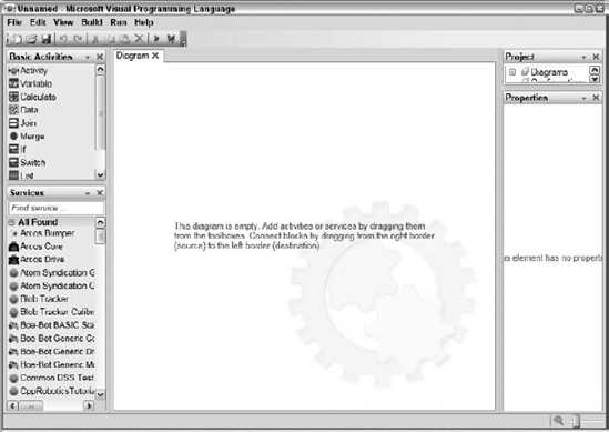
Note the following about the environment:
The main commands are accessible from the main menu bar and the most common commands are on the toolbar.
The work area consists of a central diagram area surrounded by four toolboxes. A diagram consists of one or more activity boxes that are connected together. You drag activity boxes from the various toolboxes to the central area. These toolboxes include the following:
The Basic Activities toolbox contains blocks that control data flow and create data and variables.
The Service toolbox shows all of the services available to VPL. This list includes all of the services that are present in the MRDS
bindirectory.The Project toolbox shows the diagrams and service configuration files included in your project.
The Properties toolbox shows the properties for the currently selected item so that you can view and edit the settings exposed by a service or activity.
VPL programs are called diagrams because they are defined by placing graphical icons in a diagram and connecting them with data flow connections in the VPL development environment. Once the diagram has been defined, it can be executed within the VPL development environment or you can generate an MRDS service from the diagram and run that.
The easiest way to see how a diagram works is to actually build one. The following sections describe how to create a new diagram and run it.
To create a program, follow these steps:
Start with a fresh diagram by clicking File

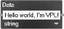
Click the data type drop-down arrow at the bottom of the activity and select string for the type of data. Type a string such as, Hello world, I'm VPL!, in the input field of the
Dataactivity. The activity should look like Figure 10-3.Now drag the
TexttoSpeechTTSactivity from the Services toolbox. The Services toolbox contains a lot of entries so it often saves time to type part of the name of the service that you need in the Search box above the list of services. This narrows the list down to only those services that contain the search text. Position theTexttoSpeechTTSactivity to the right of theDataactivity.Place the mouse on the right output pin of the
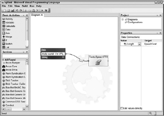
Dataactivity and drag the mouse to theTexttoSpeechTTSactivity. Notice that the corners of theTexttoSpeechTTSactivity turn green, indicating that this connection is allowed. When you release the mouse button, the Connection dialog appears. This dialog enables you to select which message is being output from the source activity and which message accepts the input in the destination activity. In this case, select DataValue in the From: box and SayText in the To: box and press OK.Now the Data Connections dialog box opens. This enables you to map a particular data value in the message output from the source to a target value in the message input to the destination. Because the data value being passed is a string, it has a value and a length. Select value in the Value box and SpeechText in the Target box. A connection should appear between the two activities in the diagram as shown in Figure 10-4.

Congratulations! You have just written your first VPL diagram. Save it by clicking File
To run a diagram, first click File
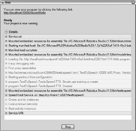
Click Run Start and press F5, or press the green forward arrow in the toolbar to run your program. A dialog box appears that shows the console output as the program is executed. After a few seconds, you should hear your computer speak the words in the
Dataactivity box. The console output window is shown in Figure 10-5.After the program has finished its execution, press the Stop button to dismiss the Run dialog.
Let's take a look at exactly what happened when this basic little diagram in Figure 10-4 was executed. The Data activity has a very simple job. When it receives a message on its input pin, it sends a message on its output pin containing the data specified. Where did the input message come from? Its input pin is unconnected. It turns out that VPL automatically sends an input message to all top-level Data activities when the program starts.
Up until now, we've been speaking about messages on wires in pretty general terms, but it's time to get more specific. You can think of a message much like a C# or C++ structure. It has one or more fields and each has a name and a type. When you specify values in the Data Connections dialog, you are actually selecting which field of the structure to send to a target value in the destination activity.
Go back to the 1-Hello project and save it to a different project name. This is important because when you make a modification to a project and then press F5 to run it, VPL automatically saves it. If you make modifications to 1-Hello and then run it, you will modify the project that was installed as part of the book software.
Select the connection between the Data activity and the TexttoSpeechTTS activity. The properties of the connection are shown in the Properties toolbox. The properties closely resemble the contents of the Data Connections dialog. Change the Value property to Length as shown in Figure 10-6.
Now, when you execute the diagram, the engine says "22" because the length of the data string was passed to the speech activity instead of its value.
Now you know that the Data activity builds a message that contains a value, which is a string and a value associated with the string, which is its length. This message is passed to the TexttoSpeechTTS activity, where, in the original diagram, the value of the string is assigned to the SpeechText input. When the TexttoSpeechTTS activity receives a message on its SayText input pin, it speaks the text passed to the SpeechText input and then sends a success or failure message on its output pin. Because nothing is connected to this pin, the message drops on the floor. Not to worry—VPL has a great little floor sweeper that gathers dropped messages and disposes of them properly.
Each activity can have one or more inputs shown as square pins on the left side of the activity icon and one or more outputs shown as square pins on the right side of the icon. When there are multiple inputs or outputs, only a single pin is shown and the desired input or output is selected with the Connections dialog when a connection is made.
Some activities have an additional output called a notification. A single response output message is generated on an output pin as the result of a single input message on an input pin. Notification outputs can also send a message as a result of an input message but they more typically send a message as the result of a change in internal state. As an example, consider the DirectionDialog activity shown in Figure 10-7.

When a message is received on the Action Input Pin, a different message is sent on the Result Output Pin, usually indicating success or failure. If the input message changes the internal state of the activity, it typically generates a notification message as well. Sometimes an external action, such as a user input event, changes the state of an activity and it spontaneously generates a notification without any input message at all.
The 3-Notifications diagram in the Chapter10 directory illustrates this behavior. It is shown in Figure 10-8.
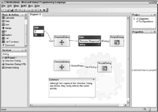
In the top row of activities, a message is initially generated by the Data activity on the left, which is sent to the Get input of the DirectionDialog activity. It sends a response message containing its state to the second Data activity, which then sends an output message containing the string "Success Response!" to the SimpleDialog activity, where it is displayed in an AlertDialog. So far you have used the Action Input Pin and the Response Output Pin of the DirectionDialog activity.
On the second row of activities, another DirectionDialog activity is shown on the left. However, this icon actually represents the same activity as the DirectionDialog in the top row. You can tell because they have the same name. When you drag onto the diagram an activity that is already present, VPL asks you whether you want a completely new activity or just another reference to the existing activity. If you specify that you want a new activity, the new activity is given a different name than the original activity. While this might initially seem confusing, it really makes the diagrams simpler because it reduces the rat's nest of connections coming from a single activity when multiple inputs and outputs are used.
The output from the DirectionDialog activity that is used in the second row is the notification output. This output sends a message to the SimpleDialog activity whenever the internal state of the DirectionDialog changes. Just like the DirectionDialog, the SimpleDialog on the second row is really just another reference to the same DirectionDialog activity shown on the first row.
This diagram also shows the use of the Comment activity. This activity has no effect on the functionality of the diagram but it provides a way to document what is going on in the diagram.
Run the diagram and notice that the response is immediately displayed as a result of the data input message on the top row of the diagram. Click the buttons on the DirectionDialog and you will see messages displayed as a result of the notifications generated by the DirectionDialog activity on the second row.
The following activities can be found in the Basic Activities toolbox. These basic activities are used to build the data connections between the activity blocks that represent services. Unlike the service activities, they do not have a unique name.
They are defined briefly in the following table and discussed in more detail in the following sections.
Activity | Description |
|---|---|
| This activity is used to get or set the value of a state variable. |
| This activity is used to calculate a value from one or more input values. |
| This activity is used to define static data that is used as an input to another activity. |
This activity waits to send an output message until it has received a message on all of its inputs. | |
| This activity forwards a message to its output from any of its inputs. |
| This activity forwards a message on the first output that has an expression that evaluates to |
| This activity forwards a message on the first output that matches the input value. |
| This activity holds a list of data. |
| This activity performs various operations on a list of data. |
| This activity displays a comment in the diagram. |
| This activity can be used to define a custom activity that, in turn, contains other activities. |
In a data flow diagram, the program state is mostly encapsulated in the messages passed between activities. Sometimes it is necessary to define state that belongs to the diagram. This state is analogous to the state in a service. Activities can set or retrieve this state. This is useful because activities do not, by default, pass the same data to their output that they receive on their input.
You use the Variable activity to define and set or get the value of a variable. When you drag a Variable activity from the Basic Activities toolbox onto the diagram, it is initially blank. Click the ellipse on the bottom of the activity to bring up the Define Variables dialog box, which enables you to add and delete variables. Any Variable activity in the diagram can represent any defined variable.
Load the 4-Variables diagram in the Chapter10 directory. It is shown in Figure 10-9.
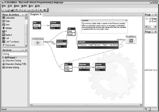
A string variable called Previous is defined and initialized using the Data and Variable activities in the upper-left corner. When a button is pressed in the DirectionDialog, a notification is sent to three different activities. The first activity to take action is the Variable activity, which gets the value of the variable and sends it to the Join activity connected to its output.
This is the first time we've used a Join activity. Its function is very simple. It waits for an input message on both of its input pins and then combines the messages into a single message and sends it on its output pin. In Figure 10-9, when the Join activity receives the output from the Variable activity and the notification from the DirectionDialog, it combines these two messages into one and sends it to the Calculate activity, which performs arithmetic, logical, or string operations on its input values according to the expression entered in the activity. These operations are shown the following table:
Type of Operation | Operation |
|---|---|
Arithmetic | +, 2, *, / and % for modulo |
Logical | &&, ||, and ! |
The plus operator (+) can also be used to concatenate strings. Parentheses can be used to group operations.
The operation defined in the Calculate activity in Figure 10-9 is "Previous:" + msg0.Previous + " New:" + msg.Name. This builds a string that contains literals combined with the string values of msg0.Previous and msg.Name. The message is displayed using the SimpleDialog activity.
All that remains is to update the value of the Previous variable. This is done with the Join activity on the bottom row. It waits until the string has been built and then combines this message with the original notification message from the DirectionDialog activity. The Calculate activity extracts the Name string from the original DirectionDialog notification and passes it to a variable activity to be stored. The Join at the bottom of the diagram is necessary because you must be certain that the string has been constructed before you change the value of the variable. Without this Join, there is a race condition between constructing the string and updating the variable that can cause unpredictable results.
Run the diagram and notice that the message displayed contains both the current button press as well as the previous button press.
No language is complete without the ability to make logical decisions and iterate through loops. In an imperative language, you use an If statement to make a decision and a For or a While statement to iterate. In VPL, decisions are made with an If activity, and iteration is done using a data flow loop.
You might expect to find a basic ForLoop activity in the Basic Activities toolbox, but it isn't there. That's because a ForLoop cannot usually be implemented in VPL with a single activity box. As you will see in the next few examples, you must take special care to ensure that the ForLoop executes in the proper order.
The diagram in Figure 10-10 shows how a simple ForLoop can be implemented in VPL. You can find it in the Chapter10 directory under "5-Loops."
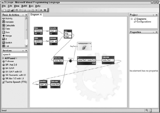
Two variables are defined: Start and End. They are given initial values by the Data activities in the upper left. When both Variable activities have been initialized, the Join activity immediately after them passes a message to the Calculate activity, which then sends a message that contains the value of the Start variable. This message is passed to the TexttoSpeechTTS activity and to an If activity. If the value of the Start variable is less than the End variable, then a message is passed along to the Calculate activity on the far right, which calculates the value of Start+1. This value is set back into the Start variable and the value of the Start variable is placed again on the wire to traverse the loop again. This continues until the Start variable is equal to the End variable, at which point no message is passed on to the Calculate block and execution stops.
There are a few interesting things to note in this diagram. This is the first time that the Merge activity has been used. When it receives an input message on any of its inputs, it simply passes that message to its output. Unlike the Join activity, it doesn't wait until all of its inputs have received a message. The Merge activity will sometimes display a yellow exclamation point with a warning that indicates a loop has been detected. VPL is trying to gently encourage you to implement loops with recursion, rather than use the Merge activity. This keeps the diagrams simpler and more readable. Implementing loops with recursion is covered in the section "Refining a Custom Activity."
The Calculate boxes that use the values of the Start and End variables don't use any of the values that are on the wire. They only use the variables stored in the diagram state. The two Calculate boxes that place the value of state.Start on the wire prior to the Merge activity are simply there to ensure that the same message is on both connections leading into the Merge activity. The Merge activity requires the messages it receives on all of its inputs to be of the same type. These messages are not actually used by any activity.
In VPL, loops are implemented as literal loops in the diagram with an If activity or other conditional to ensure that the loop doesn't continue forever.
Run the diagram to hear the beautiful sound of the numbers from 1,000,002 to 1,000,012 being read aloud. Listen carefully and you may hear one or more of the numbers read out of sequence. This occurs because there are two possible routes for messages to take after the Merge activity. VPL schedules processing for each route asynchronously. Occasionally, a message makes it all the way through the If activity and back to the Merge before the first message has been processed on its way to the TexttoSpeechTTS activity. This can cause a later message to be posted to the TexttoSpeech activity before an earlier one is posted, causing the out-of-order number reading.
The diagram in Figure 10-11 solves this problem. You can load it from the Chapter10 directory in 6-Loops (in order).
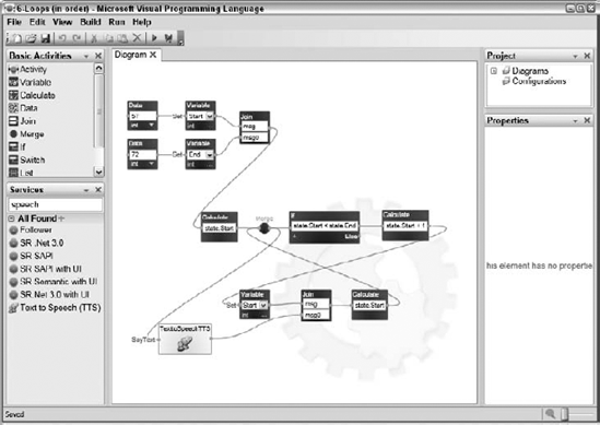
This diagram adds a Join activity after the Variable activity where the new Start variable value is saved. The Join activity will wait until the TexttoSpeechTTS activity has completed saying the previous phrase before passing an output message to the Calculate activity in the lower-right corner. This keeps the rest of the loop executing at the same speed as the TexttoSpeechTTS activity and prevents multiple SayText messages from being queued at the TexttoSpeechTTS input.
The 6-Loop (in order) diagram shown in Figure 10-11 provides a good opportunity to discuss the way in which VPL executes a diagram. It helps to understand how VPL evaluates activities and propagates messages when debugging a diagram.
A diagram is inactive until a message enters it. The message can originate from a notification on an activity or from a message that is injected into the inputs of a top-level Data activity. As long as a message is actively propagating in the diagram, VPL continues its execution.
You can see how VPL evaluates a diagram by manually tracing messages through the diagram. For the diagram shown in Figure 10-11, the diagram is inactive until VPL injects an input message into each of the upper-left Data activities. Because two messages are now active, VPL schedules a parallel thread of execution to evaluate each of them. One message propagates through the topmost Data activity and its output message propagates to the topmost Variable activity. It sets the value of the Start variable and its output message propagates to the Join activity. The Join activity has not yet received a message on its msg0 input so that evaluation thread terminates because it can no longer propagate a message.
Meanwhile, the second message propagates through the lower Data activity and to the lower Variable activity where the End variable is set, and then the message propagates to the Join activity. Because the Join activity has now received a message on both of its inputs, an output message is able to propagate and this thread continues to execute.
The message moves to the Calculate activity and through the Merge activity. The message is then sent to two activities: If and TexttoSpeechTTS. VPL spawns another thread to evaluate the message that goes to the TextoSpeechTTS activity and the previous thread continues to evaluate the diagram at the If activity. If state.Start < state.End, the If activity output message moves to the Calculate activity, through the Variable activity, and then it gets to the Join activity. Because the Join activity has not received a message at its msg0 input, no further message can be propagated and the thread is terminated.
At the same time, the TexttoSpeechTTS thread continues to execute. After this activity has completed speaking the text that was passed to it, it sends an output message to the msg0 input of the Join activity. Because a message was already received at the msg input, the Join activity propagates a message to the Calculate activity, which passes a message to the Merge activity and the loop is evaluated once again. When the message has been around the loop enough times that state.Start is equal to state.End, the output message from the Merge is sent to the If activity and, once again, another thread is spawned to evaluate the message in the TexttoSpeechTTS activity. This time, no message is propagated from the output of the If activity because its condition is false. This causes the original thread to terminate, leaving only the thread, which is running the TexttoSpeechTTS activity. When this activity completes, it sends an output message to the msg0 input of the Join activity. Because the Join activity has not received a message on its msg input, this message cannot propagate and the last thread is terminated. Because all threads have now terminated, the diagram is again inactive. There are no other sources of messages in the diagram and so it remains inactive until it is stopped.
It is useful to be able to manually trace messages through a diagram but it is much nicer to let the computer do all the busy work of this process. That is what the VPL debugger is for. You can run a diagram in debug mode by clicking Run Debug Start. This starts VPL in single-step mode. The debugger output is shown in a web page that is launched when the diagram starts execution.
The debugger is known to work with Internet Explorer but it may not work with other browsers. You should set your default browser to Internet Explorer prior to debugging VPL diagrams.
The debugger page is divided into four sections:
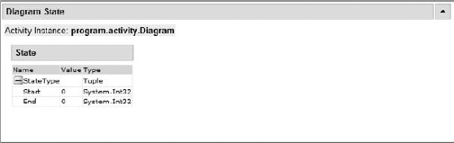
Diagram State: This is the topmost section, shown in Figure 10-12. It shows values of all of the state variables in the diagram.
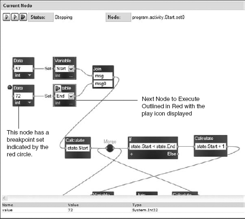
Current Node: The next section is a graphical representation of the diagram, much like the one shown in VPL. The difference is that this diagram is annotated to show the currently executing activity, activities that have been scheduled for execution, and breakpoints. As shown in Figure 10-13 (without the color), the currently executing activity is outlined with bright red, while other activities that are scheduled for execution are outlined with dark red. A red circle is shown next to activities that have a breakpoint set.
If the button on the active activity is clicked, VPL will step to the next activity. This can also be accomplished by pressing the Step button at the top of this section. The other two buttons can be used to run the diagram at slow speed or regular speed. The slow-speed execution is useful to Vtrace through large diagrams without having to continually press the Step button.
At the bottom of this section, the value of the message on the input pin of the current activity is shown.
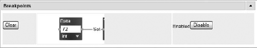
Breakpoints: The next section shows the currently set breakpoints, as shown in Figure 10-14. If a breakpoint has been set on an activity, execution will stop when it becomes the active activity. Breakpoints can be cleared, enabled, and disabled in this section.
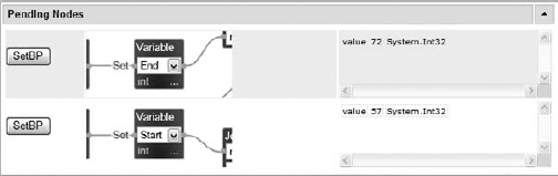
Pending Nodes: The fourth section shows all activities scheduled to be executed, as shown in Figure 10-15. As described in the previous section, multiple activities can be executing at the same time on multiple threads. A breakpoint can be set on any of the scheduled activities by pressing the corresponding SetBP button.
The diagram can be terminated by pressing the Stop button on the Run dialog, just as when the diagram is not running in debugger mode.
As shown in Figure 10-11, simple functions can be composed of many different activity blocks. Real-world diagrams can quickly become unmanageable. Fortunately, VPL enables custom activities to be defined that are similar to subroutines in imperative languages.
The ForLoop function defined in Figure 10-11 is a good candidate to become a custom activity because it is a function that might be used multiple times in a diagram and it is self-contained. This section starts by showing you how to define a custom activity to implement a ForLoop. Later you will improve that custom activity to make the ForLoop execute in order.
Defining a custom activity is very similar to defining a diagram except that the input and output pins must be defined and connected. The following steps show how to define a custom activity that implements the ForLoop functionality. You can see the final result in the 7-CustomActivity project in the Chapter10 directory.
Start out with a new project by clicking File
Drag an
Activityblock from the Basic Activities toolbox.Give the activity a name such as ForLoop by typing it in the Name: box in the Properties toolbox. Give it a friendly name and a description as well.
Double-click the
ForLoopactivity to open its diagram. The diagram page looks similar to the top-level diagram except that now input and output pins are present.Define the actions that this activity will support by clicking Edit
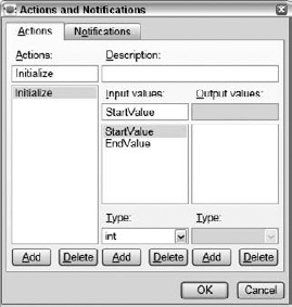
Add a new action by pressing the Add button in the Actions column. Name the action by typing Initialize in the box. Add two input values by pressing the Add button in the Input values column. Name the input values
StartValueandEndValueand make them both of typeint. A properly configured dialog is shown in Figure 10-16.Select the Notifications tab on the Actions and Notifications dialog. Add a notification by clicking the Add button in the Notifications column. Name the new notification "CountNotification." Add a notification value by clicking the Add button in the Notification values column. Name the value "Count" and give it the type of
integer. A properly configured Notifications tab is shown in Figure 10-17.The
ForLoopactivity now supports anInitializeaction that expects an input message with two integer values,StartValueandEndValue, as well as a notification output that contains a single integer calledCount. Make sure that theInitializeaction is selected on the Action drop-down menu at the top of theForLoopdiagram.Add actions to the diagram to match the diagram in Figure 10-18. The upper
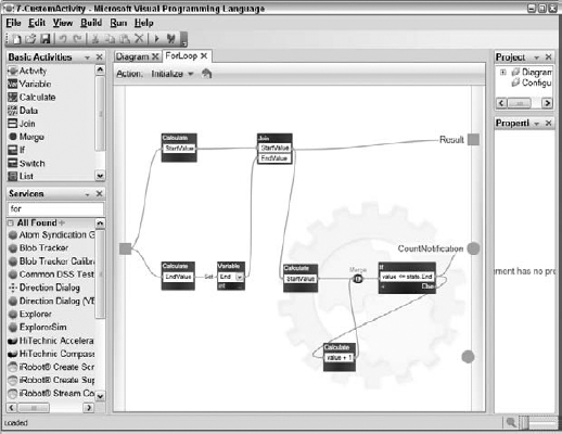
Calculateactivity extracts theStartValuevalue from the input message and then waits for theEndValueto be processed before starting the loop. The lowerCalculateactivity extracts theEndValuevalue from the input message and then sets it in theEndstate variable. This implementation of theForLoopdoes not store the incremented value in a state variable as the last implementation did. The state is maintained in the messages that are passed between activities. When both input values have been processed, a response message is sent to the outside world via the result pin. Because we didn't specify any specific types for output messages, any message will do. TheJoinactivity passes a message that once again contains both values. TheCalculateactivity extracts theStartValuevalue and passes it to theIfactivity, which only passes along a message if the value on the wire is less than theEndstate variable. This message is passed back to the outside world as aCountNotificationthat contains the count value as an integer. The value on the wire is incremented and passed back to theIfactivity to be checked again.Select the main diagram tab. Add actions to the diagram to match Figure 10-19. The two
Dataactivities are combined into a single message with theJoinactivity and sent to theInitializeaction on theForLoopactivity. Copy and Paste theForLoopactivity to create another instance of it and connect itsCountNotificationoutput to theSayTextaction of theTextoSpeechTTSactivity.

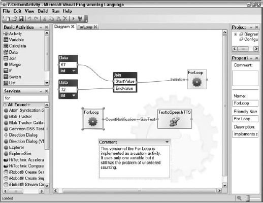
The top-level diagram is now much simpler because much of the complexity has been hidden in the ForLoop activity. It is important to design VPL diagrams in this hierarchical fashion to keep complex diagrams from becoming unwieldy.
In some ways, this diagram is a step backward from the previous one because your iteration loop has no feedback to ensure that the count is always done in the right order. In this section, you'll see how to improve the ForLoop custom activity to provide this feedback
The 8-CustomActivity (in order) project in the Chapter10 directory improves upon the diagram in the previous section by introducing a custom activity with multiple actions. It also uses fewer total activities.
The top-level diagram is shown in Figure 10-20.
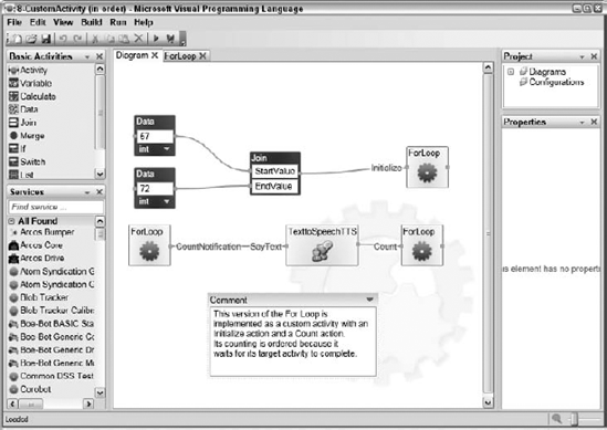
The ForLoop activity appears three times in this diagram but each reference is to the same activity. The diagram begins by combining the Start and End values into a single message that is passed to the Initialize action of the ForLoop activity. The ForLoop then sends a CountNotification containing the first count to the TexttoSpeechTTS activity. When this activity has completed, it sends a message back to the Count action of the ForLoop, which causes another CountNotification. This continues until the count reaches the End value and then the ForLoop issues no more CountNotifications. This is a clean way to use the ForLoop activity and it provides the needed synchronization to keep the count from getting out of order.
The new Initialize action in the ForLoop activity is shown in Figure 10-21.
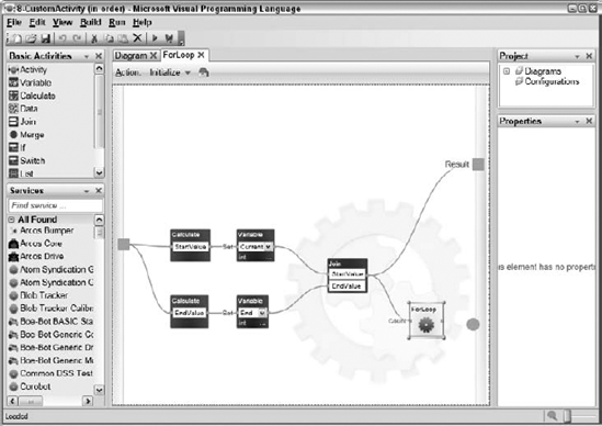
You can specify multiple actions in an activity by creating them in the Actions and Notification dialog. You then specify inputs and outputs for each action. The Action: drop-down menu at the top of the diagram enables you to select the action you are working with. Each action is independent from all the others except that they all refer to the same state variables.
In the Initialize action, the StartValue and EndValue parts of the input message are separated and stored in their respective state variables. When both values have been stored, a message is sent to the result pin to indicate that the operation has completed. You may have noticed that the ForLoop activity appears in its own action definition. This is called recursion. It is perfectly legal to pass a message from one action to the input of another action by referring to the activity in this way. Simply use the Edit menu to copy the ForLoop activity from the main diagram and then paste it into this diagram. The output from the Join activity passes a message to the Count action on the ForLoop activity. The definition for this action is shown in Figure 10-22.
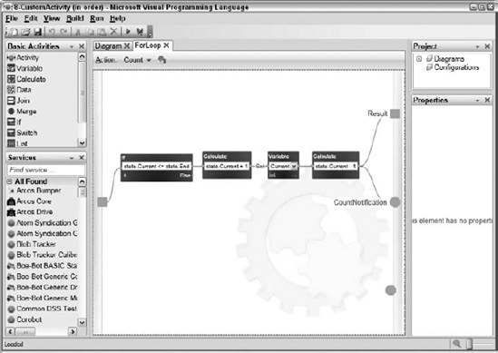
This diagram is significantly simpler than previous implementations of the ForLoop. When a message is passed to the input, the If activity determines whether any counts are remaining. If so, it passes a message to the Calculate activity, which calculates the value of the Current variable plus one and then sets it back into the Current variable. The final Calculate is used to put the previous value of the Current variable on the wire to be output as a CountNotification and a result message.
Execute this diagram to verify that it does count in the proper order and then take the time to step through it using the debugger if the execution order is not immediately clear.
Another possible way to improve the ForLoop custom activity is to add an End notification that sends a message when the loop has completed. You'll see how to add this in Example 9 in the next section.
The only activities left to describe in the Basic Activities toolbox are the List activities, the List Functions activities, and the Switch activities.
The Switch activity is much like the If activity. Instead of conditions, the Switch activity expects data values to be specified, like case statements associated with a switch statement in an imperative language. The data values are compared to the data value on the wire and the input message is propagated to the first case that matches. If none of the cases matches, the message is propagated to the Else output.
The Switch activity is useful for taking an action based on a specific data value on the wire. This is often done when implementing a state machine. In this case, the values in the Switch activity represent various possible states, and the action that the state machine takes depends on the value of the state variable.
List and ListFunctions activities are used together to manage and operate on collections of typed data. A List activity generates an empty list of a specific type. Select the type of the list from the drop-down menu at the bottom of the activity icon. All of the basic VPL types are supported.
A list may be stored in a variable like any other data value. Simply create a new variable with the desired list type and use the Set and Get actions on the Variable action to set and retrieve the list.
The List Functions activity performs one of several possible operations on a list. Its inputs and outputs depend on the function that is selected from the drop-down menu on the bottom of the List Functions activity icon. The possible functions are listed in the following table:
function | Inputs |
|---|---|
| List: A list Item: A data item of the same type as the list. The item on the Item input is appended to the end of the list and the resulting list is present on the output pin. |
| List1: A list List2: A list of the same type List2 is concatenated on the end of List1 and the resulting list is present on the output pin. |
| List: A list. A new list is constructed with the items in reverse order from the input List. The new list is present on the output pin. |
| List: A list. A new list is constructed with the items from the input List sorted in ascending order. |
| List: A list Index: An integer that represents the position of the item to be removed. Index 0 refers to the first item in the list. The resulting list is present on the output pin. |
| List: A list Item: A data item of the same type as the list Index: An integer representing the position where the item is to be inserted. Index 0 refers to the first item in the list. The resulting list is present on the output pin. |
| List: A list Item: A data item of the same type as the list. If the data item is present in the list, an integer representing its position is present on the output pin. As with the other functions, index 0 refers to the first item in the list. |
The 9-Lists project in the Chapter10 directory provides several examples showing how these activities can be used, including the Switch activity and a slightly enhanced version of the ForLoop activity from the previous section.
This diagram, shown in Figure 10-23, does text processing to transform input text into output text by replacing keywords with random words, similar to Mad Libs. In Mad Libs, a story is constructed by substituting new words into a story framework. A list of plural nouns, a list of adjectives, a list of professions, and a list of source phrases are all initialized and then manipulated by the diagram. The source phrases are replaced, if necessary, with random words from the other list and then concatenated into a final output, which is displayed in a dialog and spoken by the TexttoSpeechTTS activity.
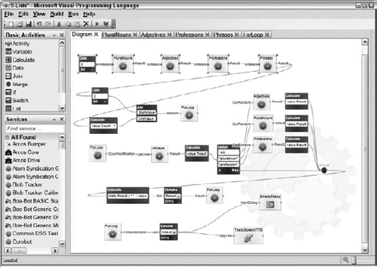
The various lists are initialized at the top of the diagram. The Data activity in the upper left passes a message to the Initialize action of the PluralNouns activity. When it has initialized itself, it passes a message from its output to the Initialize action of the Adjectives activity. The Professions activity is initialized next and then the Phrases activity. The Phrases activity outputs a message with an integer Count value that represents the number of phrases in the list. This value is used to initialize the ForLoop activity in the second row of the diagram, much like what you have seen in previous diagrams.
The ForLoop activity begins counting and passes a CountNotification message to the GetOne action input on the Phrases activity. The phrase identified by that index is passed to a Calculate activity where the value.Result string is placed on the input to the Switch activity. The Switch activity checks whether the input string is either "adj," "pluralnoun," or "profession." If it matches any of those cases, it replaces that word with a Random entry from the appropriate list by passing a message to the GetRandom action input of the associated activity. The random string is passed to the Merge activity. If none of these keywords is matched, the string is passed unmodified to the MERGE.
The updated phrase is passed to a Calculate activity that concatenates the current Result with a space and the value of the phrase. The result is stored in the Result variable and a message is passed back to the ForLoop activity telling it to generate another CountNotification.
After all of the phrases in the Phrases activity have been processed, the ForLoop sends an EndNotification message to the Variable activity at the bottom of the diagram. The value of the Result variable is retrieved and sent to an AlertDialog as well as the TexttoSpeechTTS activity.
The source text was taken from a paragraph in the MRDS documentation, which describes potential users of VPL:
VPL is targeted for beginner programmers with a basic understanding of concepts like variables and logic. However, VPL is not limited to novices. The compositional nature of the programming language may appeal to more advanced programmers for rapid prototyping or code development. As a result, VPL may appeal to a wide audience of users including students, enthusiasts/hobbyists, as well as possibly web developers and professional programmers.
Some of the words in the text were replaced with one of the three keywords described above:
VPL is targeted foradj professionwith a basic understanding of concepts likepluralnounandpluralnoun. However, VPL is not limited topluralnoun. Theadjnature of the programming language may appeal toadj pluralnounfor rapid prototyping or code development. As a result, VPL may appeal to a wide audience ofpluralnounincludingprofession, profession, as well as possiblyprofessionandadj profession.
Each time the diagram is executed, a new paragraph is generated with different word substitutions. Go ahead and run the diagram a few times to see and hear its output.
The PluralNouns, Adjectives, and Professions activities are essentially identical to each other except that they maintain different lists. The Initialize action of the PluralNouns activity is shown in Figure 10-24.
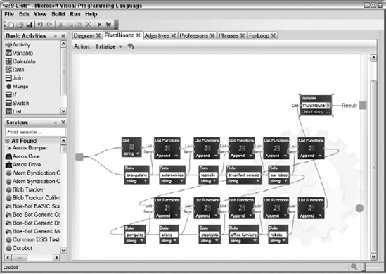
The List activity in the upper right builds a new list and passes it to the first List Functions activity when a message is received on the input pin. The first Data activity also generates a single string of data and passes it to the first List Functions activity, which then adds it to the end of the list. Subsequent List Functions and Data activities are then executed until 10 plural nouns have been added to the list. At that point, the list is stored to the PluralNouns variable associated with this activity and a response message is sent to the output pin. The Initialize actions are nearly identical for the Adjectives and Professions activities.
The Phrases activity passes the number of items in its list as an output to be used by the main diagram. Figure 10-25 shows the Initialize action of the Phrases activity. Notice how the source text has been broken up into discrete phrases so that the keywords are isolated and can be replaced before the output text is reconstructed.

The PluralNouns, Adjectives, and Professions activities support a GetRandom action that chooses a random element from each of their respective lists and places it on the output pin. Figure 10-26 shows the GetRandom action from the PluralNouns activity.
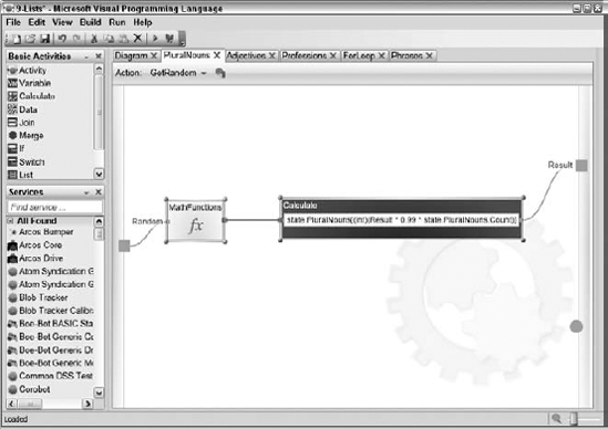
Here, the MathFunctions activity from the Services toolbox is used to generate a random floating-point number between 0.0 and 1.0, inclusive. The MathFunctions activity supports a number of math functions, including random, trigonometry, exponent and logarithm, round and truncate, power, square root, and conversion functions between radians and degrees.
The Calculate activity calculates an index into the PluralNouns list with the following expression:
(int)(Result * 0.99 * state.PluralNouns.Count)
The resulting index ranges from 0 to the index of the last element in the list, inclusive. The 0.99 factor is to slightly scale the random number so that if a 1.0 value is input, the index will not reference past the end of the list.
The syntax used to retrieve an element from the list is similar to array indexing in C#:
state.PluralNouns[(int)(Result * 0.99 * state.PluralNouns.Count)]
The string retrieved from the list is passed to the output pin.
The GetOne action on the Phrases activity is very similar except that the input integer value is used to index the list instead of a random number.
The ForLoop activity includes one small enhancement from the previous section. In the Count action, an EndNotification has been added. This notification is triggered once when the count has exceeded its maximum. The diagram for this action is shown in Figure 10-27.

This diagram is guaranteed to produce endless hours of entertainment for you and your coworkers, and with only slight modifications it can be used to generate haiku poetry for fun and profit.
This chapter has shown how to implement basic diagrams in VPL using the built-in basic activities along with a handful of services such as the TexttoSpeechTTS activity and the SimpleDialog activity. The VPL debugger was also demonstrated as a way to understand and debug diagram execution.
The next chapter demonstrates how to use VPL to control simulated and real-world robots.