
Welcome to the hardware part of the book. So far in this book you have learned a lot about Microsoft Robotics Developer Studio (MRDS), mostly using the simulator, a key feature of which is that you can use the same code to control a simulated robot as a real robot. Fortunately, this means that you already know how to drive a real robot provided that the low-level communication is taken care of for you.
This chapter provides an overview of the hardware chapters as well as some key concepts in robotics; it does not introduce new code. Subsequent chapters explain how to use a variety of real robots with MRDS. Several different types of robots are covered, including wheeled robots and a robotic arm. If you have experience with robots, you might want to skim quickly through this material. Conversely, if you have not used robots before, then you should find the chapter useful for gaining a basic understanding of the field.
Some material from previous parts of the book is discussed again in this part of the book. This is intended to make the individual parts independent of each other, although repetition is also good when you are learning new material.
Because this book is designed to introduce programmers to Microsoft Robotics Developer Studio, you should view it as a supplement to the online documentation, not a replacement. In particular, you should regularly visit the MRDS home page and check the discussion forum: http://forums.microsoft.com/MSDN/default.aspx?ForumGroupID=383&SiteID=1.
It is not assumed that you know much about robotics. There are countless textbooks on the subject of robotics and even entire degree programs with titles like "Robotics Engineering" and "Mechatronics." If you want to learn more about robotics, you should spend some time looking at your favorite online bookstore or in your local bookstore. In addition, most robot manufacturers have active discussion forums, and you can learn a lot from the experiences of other people. You might also be able to find a robotics club in your local area.
Industrial robots are not covered in this book, and it does not teach you how to build a robot starting from spare parts. It is definitely not suitable for designing and programming robots that might be used for handling hazardous materials or that operate in medical environments, especially if the application is life-critical. You should consider the robots in this book to be educational toys or research tools.
Before you get started, be aware that working with real robots can be dangerous. There are many different safety issues, but the most important ones are as follows:
Your work environment: This is the most important. Make sure that it is well lit and properly ventilated, and that there is plenty of clearance around the robot before you start operating it.
Keep away from pets and children: As they say in the movies, you should never work with children or animals. Toddlers and pets might be fascinated by your robot and want to play with it. Robots often have sharp corners and protrusions and can do unexpected things if you interfere with them, especially if you rip their sensors off!
Keep a safe distance: Robots sometimes move without warning. Even adults can trip over and fall down if a robot drives in front of them at the wrong moment. This could result in serious injury to both the human and the robot. Similarly, robotic arms can move quite fast and easily poke you in the eye if you are not careful. Therefore, make sure that you give your robots plenty of room to move.
Wear safety goggles: If you are building a robot, you will have a lot of small components. Apart from the obvious risk to children from swallowing them, these small items might fly off suddenly if a tool slips. You should therefore wear eye protection whenever you assemble (or disassemble) a robot. Soldering presents a similar risk from molten solder flying through the air if you flick the tip of the soldering iron, as well as the chance of burns from the hot iron.
Read the manufacturer's instructions: Always read the manufacturer's instructions for a robot and follow any safety warnings. Never try to push it beyond its limits or use it for purposes for which it was not intended.
That should be enough of the doom and gloom. If you act sensibly, you should have an enjoyable and educational experience. It might even be entertaining.
There are several different types of robots, but there are no universally recognized categories. Robots can be classified according to their purpose, abilities, and basic structure. Typically they are divided into categories such as mobile or stationary, autonomous or tethered, wheeled or legged, industrial versus domestic, and so on.
A common distinction is whether the robot is mobile or not. Robotic arms are usually stationary, although they can be attached to a mobile robot. Most hobby robots, however, have wheels and can run around and frighten your cat.
MRDS deals primarily with mobile robots—specifically, robots with two independently driven wheels, which are referred to as Differential Drive robots. Steering a differential drive robot is very simple because there are only two wheels. A vehicle with tracks or treads is much harder to steer because it relies on the tracks slipping in order to turn. A car (with four wheels) has what is called Ackermann steering and relies on turning only the front wheels, while the back wheels just follow along behind. A car, therefore, cannot turn on the spot, whereas a differential drive can.
One type of robot that is becoming popular is the humanoid robot. These robots are designed to look and operate similarly to a human. In other words, they have two legs (and usually arms and a head). However, they are a subset of the general category of legged robots, which include dogs (with 4 legs) or even spider-like robots (with 6 or 8 legs). One of the main areas of development for legged robots is walking gaits. As humans, we take it for granted that we can walk around on two feet, but teaching a robot to do the same and not fall over is quite difficult.
Although the Kondo KHR-1 Humanoid robot is one of the supported platforms in MRDS V1.5, it is only one of many different humanoid robots on the market. The walking abilities of these various robots vary dramatically. Many of them cannot get up when they fall over.
Articulated robotic arms use servo motors to move the joints and in some ways are similar to legged robots. No robotic arms are supported in MRDS V1.5, but Chapter 15 shows you how to use a Lynx 6 robotic arm using modified services from Lynxmotion.
Neither humanoid robots nor robots using Ackermann steering are covered in this book. The CoroBot simulation in Chapter 6 has four wheels but uses what is called skid steering.
Many robots have to be directly connected to a PC via a tether or umbilical cable. These robots are controlled by the PC and have little or no onboard intelligence. You do not download a program to the robot in this case because all of the control is performed on the PC. Robotics Tutorial 6 refers to these as remotely connected robots.
You might also hear the term teleoperation in relation to robots that use a tether. This means that a human remotely operates the robot. Using the Dashboard in MRDS or the Drive-by-Wire sample in Robotics Tutorial 4 are examples of teleoperation. In this case, the service on the PC does not perform any of the control logic—it is all left to the human operator.
Note that the tether does not have to be a physical connection between the PC and the robot. A wide variety of wireless solutions are available, such as Bluetooth, WiFi, and ZigBee. It could also be infrared, similar to a TV remote control or even a radio modem.
Note that most of the robots supported by MRDS are remotely controlled by a PC running MRDS services. When people first come across MRDS, they want to know how to use it to write programs to download into a robot. This is the way that the LEGO Mindstorms software works. For example, you can use the Mindstorms software to write code in a GUI environment that is similar to VPL and then download the code into the LEGO NXT brick for execution. The BASIC Stamp Editor is the equivalent software for the Boe-Bot, although you have to write programs in PBASIC.
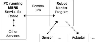
At the risk of being repetitive, MRDS does not work this way. It cannot generate code for loading into an ARM processor, a BASIC Stamp, or a PIC microcontroller. Instead, you (or the vendor) need to write a simple monitor program to run inside the robot. (The term "monitor" reflects the fact that it is not a full operating system but instead a small run-time environment with very basic functionality.) Then you write a service under MRDS that communicates with this monitor program to send commands to the actuators and receive input from the sensors.
Figure 13-1 shows this arrangement diagrammatically. Notice that the monitor program has direct access to the sensors and actuators, but the MRDS service does not. It must send and receive information via the Comms Link, which can become a bottleneck. Moreover, if the Comms Link is unreliable, or the connection keeps breaking, then the robot might become uncontrollable.
In Robotics Tutorial 6, the monitor program is referred to as an Onboard Remote Communication Interface. Microsoft has written the monitor programs for you (if necessary) for the supported robots, or the robots themselves already have appropriate onboard firmware:
LEGO NXT: When you first make a connection using MRDS, it automatically downloads and runs the necessary monitor program. Chapter 14 has examples for the NXT.
Boe-Bot: You have to load the monitor program (supplied by Parallax) into the BASIC Stamp yourself. The Boe-Bot is used in the examples in Chapter 14 and also discussed below.
The Lynx 6 robotic arm: This includes a small board called the SSC-32, which can control up to 32 servos. The firmware is already loaded into the onboard microcontroller when you get it. Chapter 15 covers the L6 arm.
Stinger: The Stinger robots have a Serializer board that controls all of the I/O and accepts commands via a serial port. This robot is discussed in Chapter 16.
Hemisson: These robots already have firmware on them that can be used to control the robot, as demonstrated in Chapter 17.
For the purposes of illustration, a simple monitor program is developed in Chapter 17 for the Integrator robot.
The monitor program must be written so that it is very responsive to requests from the MRDS service. If the monitor does a lot of "busy waits" as a way to introduce timing delays (in other words, it runs in tight loops doing nothing), then it might not be able to keep up with requests from MRDS.
As an example, consider the Boe-Bot monitor program. The BASIC Stamp used in the Boe-Bot is single-threaded. To generate the appropriate signals for the servo motors that drive the wheels, it has to output pulses of the correct duration and repeat them at a rate that is close to 50 Hz. The protocol that has been defined for the Boe-Bot, therefore, requires the PC to continuously send a command until it is acknowledged by the robot because the robot is mostly busy sending pulses to the motors. (A full explanation of the Boe-Bot protocol is available in the documentation on the Parallax website.)
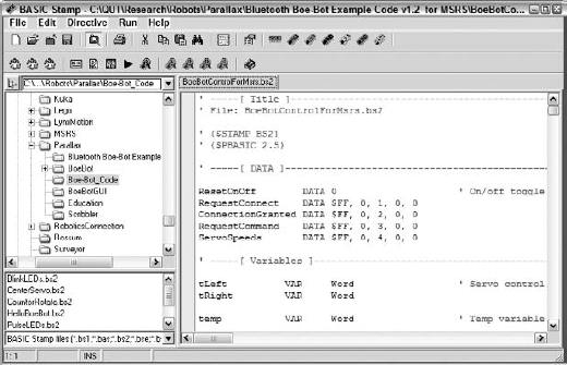
The following code is the main loop in the Boe-Bot monitor program, which is called BoeBotControlFormsrs.bs2 and is included in the software available from Parallax. The code is written in PBASIC, the native language of the BASIC Stamp, but it is quite easy to understand.
If you have installed the Parallax software, then you can double-click the filename in Windows Explorer and the BASIC Stamp Editor, shown in Figure 13-2, should start up, because there is a file association with the bs2 file type.
You must scroll down through the code to find the Main Routine, shown here:
' -----[ Main Routine ]-------------------------------------------------------

DO
  Resume:                                    ' If Message not rcvd, try again
  IF IN5 = 0 THEN Reset                      ' EB500 disconnected?

  PULSOUT 13, tLeft                          ' Servo control pulses
  PULSOUT 12, tRight

  SERIN 0, 84, 5, Resume,                    ' Get next command
       [WAITSTR buffer  2, buffer2,
       buffer3, buffer4]

  PULSOUT 13, tLeft                          ' Servo control pulses again
  PULSOUT 12, tRight
The main loop checks whether the Bluetooth adapter has disconnected, and if so it jumps to Reset. Then it issues timed pulses on the two motor control pins 13 and 12 using the PULSOUT command. The variables tLeft and tRight are the durations of the pulses and can be changed by sending a Set_Servo_Speed command to the robot. In between pulsing, the code reads from the serial port with a timeout using the SERIN command. If this command times out, it jumps back to the label Resume at the top of the loop. However, if it succeeds, the program pulses the motors once more and then continues.
Note that the Boe-Bot uses continuous rotation servo motors. The pulse width durations range from 650 (1.3ms), which is full-speed clockwise, to 850 (1.7ms), which is full-speed counterclockwise. A value of 750 (1.5ms) results in the servo staying still. (If no pulses are received, the servo also stops.)
This requirement to continuously send pulses is a significant limitation of the BASIC Stamp. In contrast, many of the PIC microcontrollers on the market can generate PWM (pulse width modulation) signals automatically—all you have to do is load the relevant registers with the timing parameters.
The following section of code checks for a restart command from the PC. If this isn't found, then it determines which of the various command codes was received from the PC by using the LOOKDOWN statement, and then executes a computed GOSUB to call the corresponding subroutine. The names of the subroutines are self-explanatory:
IF buffer2 = 192 THEN                       ' Handle restart req from PC
    msgIndex = 0
    GOTO Request_Connect
  ENDIF

  LOOKDOWN buffer2,[32, 33,
                    64, 65,
                    96, 97, 98,
                    128, 129, 130,
                    160, 161, 162], routine

  ON routine GOSUB  Set_Servo_Speed, Maneuver,
                    Get_Ir, Get_Whiskers,
                    Speaker_Tone, Set_Pins, Delay,
Enable_Digital_Sensors, Enable_Ir, Enable_Whiskers,
Disable_Digital_Sensors, Disable_Ir, Disable_Whiskers.
' Load digital sensor values into buffer byte 3 for return message.
IF flagDigSens = 1 THEN GOSUB Digital_Sensors
' Increment message index for reply. Next message from PC has to use
' reply's buf[1].
msgIndex = msgIndex + 1
buffer1 = msgIndex
SEROUT 1, 84, [STR buffer 5]
LOOPThe last part of the loop reads the digital sensors if they are enabled, and then it constructs a reply packet to be sent to the PC. This is an acknowledgment and includes a sequence number (msgIndex) so that the PC can verify that no packets have been dropped. Finally, it loops back to the top again, which immediately pulses the motors to keep them operating.
Ideally, the monitor program should use interrupts, but this is highly dependent on the hardware architecture. PIC microcontrollers and more sophisticated processors such as the ARM can handle interrupts. When an interrupt occurs as a result of an external signal, the processor saves the context (register values and processor state) and jumps to an interrupt handler. The handler does whatever is necessary and then restores the processor context so that the previously executing program can resume. This enables a primitive form of multi-tasking to be implemented. The main loop does not need to poll continuously for characters arriving on the serial port, for example, because the interrupt handler can assemble packets so that they only have to be processed once a complete packet is received.
There are two fundamentally different ways to handle sensor data: Either the monitor can periodically send updates or the MRDS service can poll the robot whenever it needs data. There are arguments both for and against each of these options, so it becomes the developer's decision.
In the preceding Boe-Bot code, you can see that the values of the digital sensors, which in this case are the whiskers and the IR sensors, can be sent back to the PC as part of every command acknowledgment. This way, the PC is usually current with the latest sensor information.
Clearly, it is not reasonable for the MRDS service running on the host computer to expect to obtain sensor values instantaneously. There is some transmission delay while a request is sent to the robot, and then the monitor has to read the sensor value(s) and send back the data. Depending on the type of connection and the speed of the CPU in the robot, this can take a few milliseconds or even tenths of a second. This means that there is an upper limit on the number of times per second that you can expect to get updates to sensor data. Stale data is a common problem in robotics.
Another issue to be aware of is that controlling the movements of a robot precisely from a remotely connected PC is difficult due to the delays involved in transmitting commands and getting feedback on what the robot is doing. Therefore, the Boe-Bot has some pre-programmed behaviors that are designed specifically to get it out of trouble if it encounters an obstacle, e.g., a whisker is depressed.
The following code implements these evasive behaviors by using timed loops to move certain distances. The PAUSE command makes the program wait for a specified number of milliseconds. Notice that the delay is 20 ms, which means that the loops execute at 50 Hz. The first loop causes the Boe-Bot to move backward. The rest of the CASE statements handle the different turn directions:
' -----[ Subroutine - Maneuver ]-------------------------------------------------------

' Preprogrammed maneuver example.  Current setup allows:
' "U"—Back up then U-turn
' "R"—Back up then right turn
' "L"—Back up then left turn

Maneuver:

  FOR temp = 0 TO 35
    PULSOUT 13, 650
    PULSOUT 12, 850
    PAUSE 20
  NEXT

  SELECT buffer3
    CASE "U"
      FOR temp = 0 TO 40
        PULSOUT 13, 650
        PULSOUT 12, 650
        PAUSE 20
      NEXT
    CASE "R"
      FOR temp = 0 TO 20
        PULSOUT 13, 850
        PULSOUT 12, 850
        PAUSE 20
      NEXT
    CASE "L"
      FOR temp = 0 TO 20
        PULSOUT 13, 650
        PULSOUT 12, 650
        PAUSE 20
      NEXT
    ENDSELECT

  RETURN
One of the side-effects of these tight loops is that the Boe-Bot does not read from the serial port while they are being executed. This means that it is effectively "deaf" for the duration of a behavior. This is obviously not desirable, but at the same time it does make it much easier to program simple wandering behaviors.
The Comms Link between the PC (MRDS service) and the robot (monitor program) is an important factor in the overall performance of the system. This can be a serial connection in the case of a tethered robot with an umbilical cable, or a wireless connection. Common types of wireless (radio) connections include IEEE 802.11b or 802.11g (also called WiFi), Bluetooth, or ZigBee. Even with a wireless connection, the usual approach is to simulate a serial (COM port) connection.
The LEGO NXT brick has built-in Bluetooth. For the Boe-Bot it is available as an optional extra circuit board that plugs into the robot. The Scribbler robot has a serial port into which you can plug a Serial-to-Bluetooth device (called a dongle). See Chapters 16 and 17 for examples using a Sena dongle.
In fact, any robot with a serial port can quickly and easily be converted to wireless operation. The software on the robot doesn't even need to know that Bluetooth is involved because the Bluetooth device establishes a virtual serial port connection.
Most PCs these days, especially laptops and PDAs, have built-in Bluetooth. Even if your PC does not have Bluetooth, there are many USB-to-Bluetooth dongles on the market and all PCs now have USB ports. The range of Bluetooth is quite good, and certainly adequate for experimenting with robots. For example, a LEGO NXT Tribot can be controlled up to 30 meters away using a laptop.
Setting up a Bluetooth connection, however, can be full of trials and tribulations. With the large number of different manufacturers making Bluetooth hardware, incompatibilities are possible. Look for advice on the Internet about which brands of Bluetooth devices are known to work with your robot before buying a device and wasting a lot of time trying to get it to work. Unfortunately, in some cases you just have to "suck it and see."
Note
The quality of Bluetooth devices on the market varies considerably. Many people have had problems getting particular brands of Bluetooth devices to talk to each other. This shouldn't happen if the devices conform to the Bluetooth specification, but it does. Several different brands of Bluetooth devices are used in this book and are therefore known to work.
If you purchase a Surveyor SRV-1, one of your options is ZigBee. ZigBee radio is a fairly new technology. It is similar to Bluetooth in a lot of ways, but not compatible with Bluetooth. Usually you install the drivers on your PC, plug in a USB-to-ZigBee device, and you are ready to start talking to the robot. You might need to select a channel, but for this you must read the instructions that came with the robot.
ZigBee is designed to support more nodes than Bluetooth (a maximum of eight nodes), and ZigBee can even be used in mesh networks. The ZigBee standard is set by a consortium, but it is basically the same as IEEE 802.15.4. It can operate in three different frequency bands, but it commonly uses the 2.4 GHz band, like Bluetooth, and has a similar range. Because it offers fewer functions (called profiles in Bluetooth), the ZigBee stack is much simpler than Bluetooth. The intended purpose of ZigBee is for low- data-rate, low-power applications such as devices that are always on. Bluetooth has a slightly better data rate, but it is still slow compared to WiFi. The main point in favor of Bluetooth over ZigBee is that it is available in so many devices these days, such as laptops and PDAs.
To set up a WiFi link, you must either use a so-called ad-hoc or peer-to-peer connection with fixed IP addresses or you need a Wireless Access Point to operate in that is called infrastructure mode. A Wireless Access Point (WAP) can issue addresses via DHCP. However, if the robot gets different addresses each time it is turned on, this makes communicating with it more complicated. It is far preferable to hard-code the IP address on the robot.
If you are trying to operate in a corporate environment, you might run into quite restrictive policies regarding connecting to the building's wireless network and you might not be allowed to hard-code an address. Access might be limited to known MAC addresses, or you might be required to install special software that establishes a VPN (virtual private network) in order to use encryption to ensure security. You might find it easier to buy your own wireless access point, although the "network police" might find you because you might interfere with the corporate network. Of course, if you are working at home, then you will need to set up your own wireless network anyway.
If you have a robot with an onboard PC, the setup is similar to your desktop or laptop. However, for the embedded WiFi cards used on some robots, you have to follow the manufacturer's instructions and it simply might not be possible to configure the robot to work with a corporate network. A discussion about how to set up wireless networks, and advice on the wide range of scenarios, is outside the scope of this book.
The most important distinction for this book is whether a robot is autonomous or not. An autonomous robot has an onboard computer capable of running Microsoft Robotics Developer Studio. The computer might be running Windows CE, Embedded XP, or even Vista. Typical hardware ranges from SBCs (single-board computers) to PDAs (personal digital assistants) and laptops.
SBCs come in a variety of formats. One of the earliest was PC104, an industry standard specification for a small embedded PC. However, manufacturers such as VIA Technologies have developed their own formats for small computers, including nano-ITX and pico-ITX. The pico-ITX boards are less than 10 cm square (about 4 inches) and have low power requirements, but they are still full x86-based PCs.
Programming under Windows CE requires additional skills beyond simply programming under Windows XP or Vista. The CE environment only supports a subset of .NET called the Compact Framework (CF). In addition, you have to transfer your programs from your development machine to the target PC on the robot. See Chapter 16 for more information.
Even though the PC is located directly on the robot, it still needs an interface board to control the actuators and read from the sensors. This controller board might contain a PIC microcontroller and have its own communications protocol. Therefore, a monitor program might still be required.
The Sumo robots used in a competition sponsored by Microsoft at the MEDC conference in 2007 were autonomous robots. They were based on the iRobot Create with an eBox-2300 PC mounted on top and a Logitech webcam. The onboard PC talks directly to the robot using a serial port.
The ICOP eBox is available in a Jump Start Kit that runs Windows CE. See www.icoptech.com/products_detail.asp?ProductID=272. This same PC is used on the Stinger CE robot discussed in Chapter 16.
It is possible to monitor the operations of an autonomous robot remotely, or even to give it supervisory instructions. In this case, the onboard computer directly controls the robot, but higher-level strategies are implemented in a separate computer. Communication is usually via WiFi, which has become quite popular due to its low cost and good range. A WiFi card can be purchased as an optional extra for the eBox-2300.
In order to run MRDS, the onboard PC on the robot must have .NET V2.0 installed. You don't run Visual Studio on this PC (unless, of course, it is a laptop, in which case you can run whatever you like). Instead, you develop the services on a desktop PC and download them to the robot's PC.
In addition, it is not necessary to install the full version of MRDS on the robot because a utility called DssDeploy can be used to package up a set of services. (DssDeploy is discussed in Chapter 3 for desktop PCs, and again in Chapter 16 in relation to installing a package on a PDA or embedded PC.) It automatically determines the dependencies and includes the necessary components to make a run-time version of MRDS. This saves memory, which is often at a premium on an embedded PC or PDA.
The procedure you use to deploy your services to the robot varies according to the type of PC that you are using on the robot and the communications hardware that it has installed. Common approaches include using USB flash drives, connecting via WiFi, and even downloading via a serial port, although this should be avoided because it is extremely slow.
The type of robot you choose to work with depends on several factors, including the intended purpose and your level of expertise with hardware. (It is assumed that you are competent with software!) As previously stated, this is an introductory book and it does not cover industrial robots, but the principles that apply to educational robots also apply to industrial robots. For example, KUKA is a major manufacturer of industrial arms, and they have developed MRDS services and a set of tutorials, available from www.kuka.com.en.products/software/educational_framework.
Several robots have been selected for use in the examples in this book and are outlined briefly below. They cover a range of different types and prices, although the objective has been to keep them within a price range that a student or hobbyist can afford. If you are a teacher, then it is important to keep the price down because you need multiple robots in the classroom (as well as PCs).
Information on prices is deliberately vague because prices are constantly changing.
Conversely, if you are a researcher, then you might have access to some very expensive robots (such as the MobileRobots Pioneer 3DX) and devices (such as a SICK Laser Range Finder) that are supported by MRDS. The principles in this book translate to research robots as well, and MRDS has already been used successfully to control a Segway with a robotic arm balanced on top, a car for the DARPA Urban Challenge, an unmanned underwater vehicle, and even a huggable robot. For the latest examples, see the Microsoft Robotics Developer Studio Community web page at http://msdn2.microsoft.com/en-au/robotics/aa731519.aspx.
It is clearly not possible to cover every available model of robot. This is especially true for home-brewed robots. Questions are often posted to the Microsoft Robotics Developer Studio Discussion Forum at http://forums.microsoft.com/msdn/default.aspx?forumgroupid=383&siteid=1 from new users who are hoping to build their own robots. Some of these people have unrealistic expectations about what their robots will do (probably because of what they have seen in science-fiction movies) and how easy it will be to build and program them.
If you have no experience with robots, then it would be best for you to select a robot kit or even a pre-assembled robot as your first choice. With that in mind, here are some general recommendations:
MRDS uses Windows platform code only. A common type of question is "How do I program my brand xxx robot with an onboard model xxx PIC microcontroller using MRDS?" The answer is, you don't! MRDS does not generate code for anything other than Windows platforms. (Actually, it generates .NET code, which is platform-independent, but that basically limits MRDS to the various flavors of Windows.)
If your robot has some sort of onboard CPU and you want to program it directly, then you should investigate the options available from the manufacturer. Many robots, including the LEGO Mindstorms NXT, Parallax Boe-Bot, RoboticsConnection Stinger, and so on, have programming tools available for them that enable you to run programs directly on the robot. In some cases, these are GUI tools similar to VPL. In other cases, they might use C-like languages or BASIC.
Use a wireless connection between your PC and your robot. This eliminates the need to attach the robot to the PC via a serial cable, which severely limits the robot's freedom to move around. Many of the robots on the market have a Bluetooth module, although it is sometimes an optional extra. This requires Bluetooth hardware to be installed in your PC; otherwise, you have to purchase a USB-to-Bluetooth device. For testing robots within a typical office or laboratory environment, Bluetooth provides adequate range and is usually reliable.
An alternative to Bluetooth that is becoming popular is ZigBee radio (see the official website at
www.zigbee.org/en/index.asp). It has similar capabilities to Bluetooth and the communications modules cost about the same.If you can, get a robot with a WiFi (wireless Ethernet) interface. More expensive robots, especially research robots, often use what is called serial Ethernet whereby the serial port on the robot is connected to an Ethernet interface. Packets are sent to and from the robot exactly as though the PC were connected via a COM port and a serial cable—the WiFi connection is transparent to the robot.
In selecting robots for this book, several factors were taken into consideration. The purpose of the book is not to teach robotics, but rather to demonstrate how to use Microsoft Robotics Developer Studio to control robotics hardware. Therefore, the robots were chosen for their educational value. They are not industrial robots. However, they do cover several categories of robots, including mobile robots (both autonomous and tethered) and articulated robotic arms. As stated previously in this chapter, humanoid and legged robots have deliberately been omitted. Much of what you learn from a robotic arm is applicable to legged robots because they both rely on joints.
A good starting point for information about other robots is the MRDS Community Page, which contains the latest list. It can be accessed from the Community tab on the MRDS home page or using the following URL: http://msdn2.microsoft.com/en-au/robotics/aa731519.aspx.
You should also check the vendor's website for the latest information and software for your robot. Most robot vendors have discussion forums or support pages, including Frequently Asked Questions (FAQs) or Knowledge Bases.
The last chapter in this book (Chapter 17) explains how to set up new robot hardware, but it is recommended that you first gain some experience with one of the robots listed here. The two robots in Chapter 17, the Integrator from Picblok and the Hemisson from K-Team, are not mentioned below because they don't have the same level of support as the other robots.
Note that the robots are listed in order of complexity for new users, so if you are a novice you might like to start with the first robot and work your way through the list. Over a period of time, you might want to buy more than one of these robots. Each of them has its own advantages and disadvantages, and they will all teach you different lessons about robotics.
The primary advantage of the LEGO Mindstorms NXT kit is that it doesn't require any tools or special skills. Everyone knows how to assemble LEGO, right?
The LEGO Mindstorms NXT kit, which is the successor to the RCX, is a great robot to get started with. It sells for different prices around the world, but in the United States it retails for around $250. It is easy to build and has built-in Bluetooth. You can also design your own robots and even switch from using wheels to legs. You are limited only by your imagination and how many LEGO blocks you own. See http://mindstorms.lego.com/Products/Default.aspx.
The basic intelligence is provided by a pre-built "brick," and Bluetooth is built right into the brick. LEGO offers a wide variety of sensors for the NXT, and there are third parties that sell NXT sensors. A disadvantage of the LEGO NXT brick is that it can only handle four sensors and three motors. The motors have internal encoders to measure rotations, but the maximum resolution is 360 ticks per rotation.
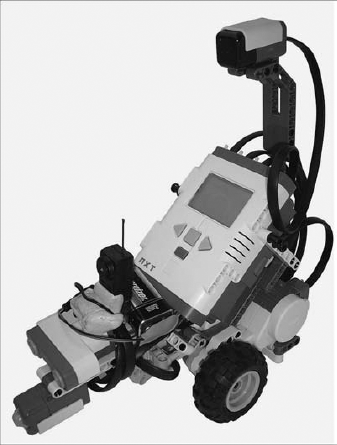
The LEGO NXT Tribot (which can be used in the simulator and is supported by MRDS) requires about an hour to assemble. However, the LEGO Mindstorms NXT kit can also be used to build other robots. There is an active online LEGO NXT community. Due to its popularity, the LEGO NXT Tribot is covered in Chapter 14. Figure 13-3 shows a LEGO NXT Tribot loaded up with a range of sensors.
In October 2007, Microsoft released updated services for the LEGO NXT that provide additional features and support third-party sensors such as the HiTechnic Compass. Make sure that you download and install these services, or preferably install the MRDS V1.5 Refresh.
Parallax also makes a robot called the Boe-Bot that is available in kit form specifically for MRDS, which includes a Bluetooth module and a USB-to-serial device, for about $210 (U.S.). The Boe-Bot uses a BASIC Stamp for its onboard intelligence—the same processor used in the Scribbler discussed below. See www.parallax.com/ProductInfo/Robotics/BoeBotRobotInformation/tabid/411/Default.aspx.
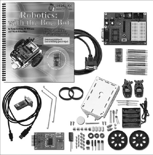
If you are considering buying a Boe-Bot, make sure you order the kit specifically for MRDS, which is shown in Figure 13-4. You can see an assembled Boe-Bot in Chapter 14.
The Boe-Bot is a slightly more complicated robot to build than the LEGO NXT, but it is cheaper. The instruction book that comes with the Boe-Bot is quite easy to understand. The most difficult task is adjusting the servo motors for the wheels so that they don't turn when you set the speed to zero. If you are an experienced programmer, though, you might find that it is too low-level. This is because the intended audience is students age 13 and older.
A primary advantage of the Boe-Bot, at least in an educational setting, is that it has a small breadboard on the Board of Education (BOE) circuit board. A set of electronic components, included in the kit, can be used to build sensors directly on the robot. These components include LEDs for displaying program status, a piezoelectric speaker for making sounds, and the necessary parts for simple infrared detectors. If you have a background in electronics, you can design and implement your own sensors or other output circuits without soldering.
Additional sensors are also available from Parallax, including sonar and a line-follower kit. These are not supported under MRDS, so you would have to write your own services.
The Boe-Bot uses a BASIC Stamp for its onboard intelligence. The BASIC Stamp Editor is a language-sensitive editor that understands and compiles PBASIC code. It also takes care of downloading to the Boe-Bot, making it a trivial task. Extensive documentation is provided and PBASIC is fairly easy to learn. In any case, you shouldn't need to use PBASIC because you can simply load the monitor program into the Boe-Bot and then control it remotely using MRDS on your PC via Bluetooth.
Although the Boe-Bot is supported in MRDS V1.5, the support is patchy. Some of the code is supplied with MRDS; the rest you have to download from Parallax. Therefore, the authors provide improved versions of the Parallax services for the Boe-Bot with this book in Chapter 14. The updated services enable you to flash LEDs and sound the buzzer. They also implement the DriveDistance and RotateDegrees operations, which are missing from the MRDS services. Lastly, they also include Compact Framework (CF) versions of the services. Chapter 16 provides instructions on how to drive your Boe-Bot using a PDA with built-in Bluetooth, such as the Dell Axim X50v.
If you are interested in articulated arms, the Lynx 6 is a reasonably priced (about US$390) and fully functional arm, which is shown in Figure 13-5. Lynxmotion also has more robust, and expensive, arms available. See www.lynxmotion.com/Category.aspx?CategoryID=25 for more information.
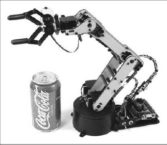
Don't be misled by the picture of a Coke can in Figure 13-5. The arm is nowhere near strong enough to lift a full can. It is just there to show you the relative size of the arm.
The Lynxmotion L6 is a five DOF (Degrees of Freedom) articulated arm with a gripper. The axes include the Base (rotate), Shoulder, Elbow, and Wrist (Rotate and Tilt). There is also an L5 model, which is cheaper because it doesn't include the Wrist Rotate, but the L6 is a better choice.
Because dealing with joints in articulated arms is so different from the wheels on a differential drive robot, it is something that you would do only if you had a particular interest in or reason for using an arm. These differences are one of the reasons why the L6 is covered separately in this book in Chapter 15.
There is some very complicated mathematics involved in moving an arm, called inverse kinematics. The software supplied with this book takes care of this, but there is more to it than calculating the necessary joint angles to move the end effector to a specified pose. You also need to consider the speed and torque limitations of the robot. Otherwise, you can damage your robot by inappropriate movements.
The L6 comes as a kit that you have to assemble yourself. It is a more involved task than the Boe-Bot and takes much longer to put together and test. It is not a job for inexperienced users. The parts are made out of lexan (a very tough plastic) and have very tight tolerances, making them hard to fit together.
There is software supplied with the L6 called LynxTerm that can be used to control the servos. This is a good way to test the robot prior to using MRDS. Another much more sophisticated program called RIOS is also included.
Note
All of the assembly guides for the L6 are online, so you have to download or print them. You should read the guides before purchasing the L6 because the construction is fairly involved and you need some tools that are not included in the kit. If you have no experience in building kits, then this is probably not a good robot to start with.
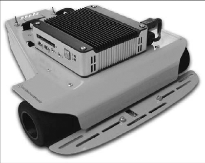
The final robot, shown in Figure 13-6, is the Stinger CE from RoboticsConnection, which costs around US$525. It is an autonomous robot that uses the eBox-2300 running Windows CE (hence the "CE" in the name of the robot). You can get more information at www.roboticsconnection.com/pc-78-3-stinger-windowsce-kit.aspx.
RoboticsConnection originally released a robot called the Traxster (because it uses tracks or treads) that was supported under MRDS V1.0. It uses the Serializer controller board. The Serializer is the core component of a new robot called the Stinger. See www.roboticsconnection.com/c-3-robot-kits.aspx for more information. The Stinger is the successor to the Traxster.
Communication is via a serial port. The eBox attaches to the top of the Stinger and then connects to the Serializer using a serial cable, thereby making the robot autonomous. However, there are alternatives with a variety of communication modules available for the Serializer, including Bluetooth, ZigBee, and WiFi.
For example, you can purchase a standard Stinger robot with a Bluetooth module. It can then be driven in the same way as the LEGO NXT or the Boe-Bot. This enables you to become familiar with the Stinger and the Serializer board without the additional complexity and cost of the eBox-2300.
The eBox-2300 is the same PC104 computer that is used on the Sumo robots based on the iRobot Create. Some of the instructional material on the Stinger is also applicable to the Sumo robots because they use the same onboard PC. However, the Stinger has to be built from a kit, whereas the Create comes already built. This gives you a lot more flexibility regarding how you arrange the sensors, and which sensors you put on the robot, but at the cost of your time and labor.
Unless you have some prior experience with building kits, this should probably not be your first robot. The Stinger itself is easy enough to build. It comes with a great set of instructions in a multimedia PDF file that includes 3D animations and synthesized voice instructions. However, setting up Windows CE and developing code for it is more complex than programming for Windows XP or Vista. This makes the overall task more difficult.
The Stinger instructions require Adobe Acrobat version 8.1 or later and a sound card in your PC. The actual PDF file is around 21MB and must be downloaded from the RoboticsConnection website.
Support for the Stinger under MRDS V1.5 is available from the RoboticsConnection website. Chapter 16 discusses how to use the Stinger CE with MRDS and run services directly on the robot. An optional WiFi card is also available for the eBox, although it is not necessary because the eBox can run on its own.
The following is a very brief summary of some other robots that are available and suitable for use with MRDS without a significant amount of additional programming.
Because bipedal, or humanoid, robots tend to be much more expensive than wheeled robots, no recommendations are made here. The only humanoid robot supported by MRDS V1.5 is the Kondo KHR-1. Humanoid robots rely on joints in a similar way to robotic arms, so using a robotic arm is a good starting point.
Similarly, quadruped robots (usually robotic dogs) have also been ignored. There have been competitions for these types of robots in the past, but the robots are expensive, and until Microsoft ran a competition using the RobuDog simulation from Robosoft (www.robosoft.fr/eng/index.php), they were not supported under MRDS. The RoboCup RoboSoccer Four Legged League (www.robocup.org) has used the Sony AIBO in the past, but since 2008 the league has been renamed the Standard Platform League and will be based on a new humanoid robot called the Aldebaran Nao from Aldebaran Robotics. Refer to www.aldebaran-robotics.com/eng/index.php for more information.
The list of robots supported by MRDS is constantly changing, especially as third parties develop their own services. This type of information becomes obsolete very quickly. The following list is in order of increasing price.
If you are simply interested in learning about robotics and have no prior experience, then a prebuilt robot is probably the best starting point. For example, the Scribbler robot from Parallax (www.parallax.com/ProductInfo/Robotics/ScribblerRobotInformation/tabid/455/Default.aspx) is relatively cheap (around US$80) and comes preassembled and ready to use out of the box. It is more like a toy—it is very basic and cannot be expanded. You need to buy a Bluetooth device to attach to the robot so that you can operate it without using a serial cable. The Sena Serial-to-Bluetooth device (see Chapter 16) is suitable for this.
MRDS services for the Scribbler were originally developed by Ben Axelrod for the Institute of Personal Robotics Education (IPRE) while he was a graduate student at Georgia Tech. Services for MRDS V1.5 are available from the IPRE resources page: www.ipre.org/resources.html. Note that you have to update the firmware inside the Scribbler to use the IPRE services.
IPRE has developed a hardware "dongle," called a Fluke, that has an onboard color camera, IR range sensing, internal voltage sensing, an extra-bright LED, and Bluetooth. These became available for purchase in early 2008 and cost about US$80. It plugs into the Scribbler's serial port and can reprogram the Scribbler's firmware by downloading code over Bluetooth. This is an attractive alternative to buying a serial-to-Bluetooth device. The Fluke is shown attached to a Scribbler in Figure 13-7, courtesy of Tucker Balch at Georgia Tech.
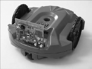
This device is interesting for two reasons. First, the inclusion of a camera shows the importance that educators place on vision for robots. Second, it is likely that small robots combining the functionality of the Scribbler and the Fluke will become available, which raises the bar for entry-level robots.
Note that IPRE provides educational materials for teaching robotics, but the Myro (My Robotics) software is based on Python and it does not use MRDS. This will change over time.
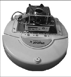
Another alternative is the iRobot Create (www.irobot.com/sp.cfm?pageid=305), which is basically a Roomba vacuum-cleaning robot without the vacuum cleaner, redesigned specifically for educational purposes. It is relatively cheap, at about US$130, and it comes preassembled. You will also need to buy a Bluetooth device. Unfortunately, at the time of writing the Create is not available for sale outside of the U.S.A. and Canada.
The Create is discussed in Chapter 9 in relation to the sumo competition that Microsoft ran in 2007. Figure 13-8 shows one of the robots used in the sumo competition with an eBox-2300 and a Logitech webcam mounted on top. A simulated iCreate is also used in Chapter 12 for line following and sumo.
The iRobot Roomba and Create robots have a microcontroller that can be controlled directly via a serial port. You can attach a Serial-to-Bluetooth device to the serial port on the robot and control it. The firmware is already installed and the serial protocol is clearly documented. The RooTooth (www.roombadevtools.com) is a popular device for Bluetooth connections.
If you are interested in computer vision, then you might want to consider the Surveyor SRV-1 for about US$465 (www.surveyor.com).
This robot was undergoing a major revision at the time of writing, with the onboard computer being upgraded to a much faster Blackfin processor. Figure 13-9 shows the original SRV-1 (left) and the upgraded SRV-1b (right). Its main advantages are that it is preassembled; includes a camera; and offers a choice of Bluetooth, ZigBee, or WiFi. There is software for computer vision available from RoboRealm that supports the SRV-1 and works with MRDS (www.roborealm.com/help/MSRS.php).

For vision applications, it is important to get the fastest possible connection to the robot. WiFi is at least five times faster than Bluetooth, at 11Mbit/sec for 802.11b, and 25 times faster for 802.11g, at 54Mbit/sec.
The SRV-1 is another one of the robots that is targeted by IPRE for use with Myro.
The authors have updated the MRDS services for the SRV-1 to support the generic webcam contact and reduce flooding effects on the DifferentialDrive service so that the robot can be used with the TeleOperation service in Chapter 4. These updated services are available from the book's website. Services for the SRV-1b that operate using TCP/IP over WiFi will also be made available.
The Corobot from CoroWare (www.corobot.net) is a four-wheeled robot with an onboard PC. Figure 13-10 shows a Corobot with the optional robotic arm attached. It comes with a webcam as standard and there is an optional robotic arm attachment. CoroWare has some sophisticated software that runs under MRDS.
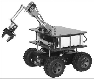
Chapter 6 develops a Corobot simulation, which is used again in Chapters 7, 9, and 12. However, there is no coverage of a real Corobot in this part of the book because the authors did not have access to one.
With a price around US$3,000, this robot is probably out of the price range of the average hobbyist and is targeted more at researchers, academics, and the military.
The PC-BOT, as its name implies, includes a full-blown PC that runs Windows XP and has a DVD drive, hard disk, speakers, webcam, wireless Ethernet, and so on. It has been available on the market for some time, but at US$8,000 it is not likely to be the first choice for a beginner. The original version came with MRDS installed, as well as all the necessary services and software to support directly programming the robot in .NET applications. See the PC-BOT home page for more information (www.whiteboxrobotics.com/PCBOTs/index.html).
One exciting announcement in late 2007 was that the 914 PC-BOT is also to be sold by Heathkit under the name HE-RObot. Heathkit has a strong reputation in hardware training and educational systems. You can see the Heathkit version of the robot at www.heathkit.com/herobot.html.
At the time of writing, the PC-BOT does not support MRDS V1.5. Services were released for the original V1.0 but the White Box has not updated them. However, it is their intention to support MRDS in the future, so perhaps this will happen with V2.0.
The Pioneer robot family has been used for years in research institutions. However, a 3DX with a SICK Laser Range Finder costs over US$10,000. MobileRobots sell a whole range of robots, some of which are cheaper, such as the AmigoBots. All these robots are available with WiFi as an option and have an onboard processor, wheel encoders, sonar sensors, and everything that you might expect in a high-quality research robot.
The Pioneer 3DX is one of the robots supported in the simulator. The ExplorerSim in Chapter 9 and the VPLExplorer in Chapter 12 use this robot specifically because it has an LRF, which is a very accurate range sensor.
For more information, see www.activrobots.com/ROBOTS/p2dx.html. (The URL is correct—MobileRobots used to be called ActivRobots, and for some reason the P3DX is on a page called p2dx.)
Although you can learn a lot about MRDS simply by working through the Simulation chapters in this book, there is no substitute for using real hardware. Yes, hardware is messy, unpredictable, and often frustrating. It can be complicated to build and sometimes it doesn't do exactly what it is commanded to do. However, nobody will ever believe that you are a true roboticist unless you have experience with real hardware.
This section briefly addresses the various components of a robot. The key points to note are that hardware is often nonlinear and that it has limitations. It should be obvious that interfacing a computer with a robot requires specialized hardware.
A robot requires input data, which is collected from its environment. This data comes from sensors (also called transducers). Without sensory input, the robot would drive around blind and bump into things—not a very useful outcome.
Once the robot has received some inputs, it needs to process this data to make decisions. Based on these decisions, it can then take some action. A controller does the work of making decisions. Usually the controller is given some task to perform. Depending on the type of controller, it might be a low-level task such as driving in a straight line, or a high-level task such as finding victims after a disaster.
Regardless of the task to be performed, the robot needs to interact with the real world, and for this it needs actuators. Actuators take a variety of forms, but two are very common: the differential drive, consisting of two independently driven wheels, and the joints in robotic arms, which are based on servo motors. In addition to actuators, there might be other output or display devices. Status information is commonly displayed using LEDs.
One important distinction between various types of sensors and actuators is whether they are digital (binary values—usually represented as a bool) or analog (a continuous range of values—usually stored as a double). Obviously, switches and lamps are digital devices because they can only be on or off. Analog input devices require an analog-to-digital converter (ADC) to convert quantities such as voltages, temperatures, pressures, and so on, from the real world into numbers inside a computer. A digital-to-analog converter (DAC) does the opposite and can be used to convert a number, such as a speed, to an output, such as a voltage to control a motor.
The sensors, controller, and actuators are usually connected in a feedback loop or control loop (sometimes also referred to as closed-loop control). One of the most commonly used types of feedback controllers is the Proportional-Integral-Derivative (PID) controller, which is explained in a little more detail below.
One of the objectives of MRDS is to create abstract versions of the various sensors and actuators and then connect to the real devices at runtime by defining partners in a manifest. For this reason, MRDS defines generic contracts for a variety of sensors and actuators. When you build a new MRDS service, you can use these generic contracts so that your service can connect to a variety of devices at runtime. For example, an Analog Sensor service included in MRDS can be used to build a service for any sensor that outputs an analog signal (usually a voltage), as opposed to a digital (or binary) signal.
The following three sections discuss sensors, actuators, and controllers in more detail. There is no attempt to cover all types of sensors and actuators, but rather to discuss the ones that you will commonly encounter when using MRDS. If you have experience with robots, then you might want to skim through these sections because they are background material.
There are two types of sensor data: proprioceptive and exteroceptive. These terms just mean internal and external, respectively.
Internal information could include things such as the battery voltage, which a robot needs to monitor to prevent it from running out of power and to signal the need for a recharge. MRDS includes a Battery service. Other examples include temperature sensors to ensure that the robot is not overheating, and stall sensors on the motors that detect when the robot is stuck and can be used to shut down the motors to prevent them from burning out.
External information is obtained from the world around the robot, such as the distance to the nearest obstacle, a GPS location, the current compass heading, the ambient temperature, or even images from a video camera. Notice that in most cases the sensor information can be represented by a single number that has a minimum and a maximum value. The Webcam service is the obvious exception because it provides an array of pixel values.
The following sections discuss various types of exteroceptive sensors.
The simplest of all sensors is a contact sensor, also called a bumper. A bumper is just a switch that senses when the robot runs into something, so it only has two states: pressed or not pressed. The LEGO NXT has a touch sensor that is a bumper. Some robots, such as the Boe-Bot, have "whiskers," which are thin pieces of wire that flex when the robot runs into something, causing an electrical contact to close.
Bumpers are called contact sensors because the robot actually makes contact with (bumps into) the obstacle. If this obstacle happens to be a human, then it could be harmful to the human! If it is a wall, then it might damage the robot. Either way, this is not a good sensor to use for general navigation. Therefore, bumpers are usually used as a last resort in case the other sensors have failed to detect an obstacle. Even expensive robots such as the Pioneer 3DX have bumpers on the front and back as a fail-safe measure. In the case of the 3DX, there are several bumpers, which MRDS refers to as a bumper array.
It is also possible to have virtual bumpers that don't involve physical contact. In Chapter 17, for example, the Integrator robot has an infrared sensor that detects obstacles, but the output of the sensor is a binary value—on or off.
Obviously, it is much better if the robot can sense obstacles from a distance, rather than bump into them. Several types of sensors, usually referred to as range sensors, can provide distance information. Examples include infrared (IR) detectors, sonar sensors, and laser range finders. These are also commonly called time of flight sensors because they send out a signal (infrared light, ultrasound pulse, or laser beam) and wait for a reflection to come back. The time required for the echo is a measure of the distance. You have probably seen movies involving submarines and have heard the "pings" sent out as the sonar searches for enemy ships.
On many hobby robots, infrared sensors are the preferred type of sensor because they're cheap. However, they're noisy and nonlinear, meaning that they do not always produce reliable readings and the values from the sensor are not directly correlated to the robot's distance from an obstacle. (See Chapter 17 for a graph showing the response of IR sensors on a Hemisson robot.) They are also susceptible to interference from strong sunlight (so they might not work at all outdoors), and they work over a very short range (typically 5 to 50cm).
Passive IR sensors just look for reflected infrared signals, which are all around us (but we can't see them). Active IR sensors work by sending out pulses of infrared light at a fixed frequency and then watching to see whether there is a reflection. Both of these types of sensors are effectively on/off sensors, or what MRDS refers to as "bumpers" although in this case there is no physical contact.
The cheapest IR sensors only indicate that an obstacle is somewhere within a fairly narrow range of distances. The exact range depends on the frequency of the IR pulses. In this case, the input signal is digital, i.e., 0 or 1. Many people do not realize this when they first start working with hobby robots. The absence of range data means that it is not possible to build reliable maps of the surrounding environment. It is also possible to miss obstacles if they are too close to the robot, such as a foot if a person suddenly steps in front of the robot.
The frequency and sensitivity can be adjusted to change the distance at which the sensor is triggered by an obstacle. This is usually done by changing a resistor or adjusting a potentiometer. An approach used in the Boe-Bot documentation is to change the frequency of the IR signal. A sweep of multiple frequencies enables the distance to an obstacle to be determined, but only in very rough bands. (MRDS does not use this method.)
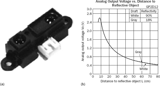
More expensive IR sensors give an actual measurement of the range. There are usually several sensors located around the outside of the robot so that it can see in many directions simultaneously. For example, the Stinger robot in Chapter 16 uses three Sharp sensors across the front. These can measure distances from 10 to 80cm. An example of a Sharp GP2D12 IR sensor is shown on the left in Figure 13-11; shown on the right is its response to obstacles, sometimes referred to as the measurement model.
Sonar sensors use ultrasonic "pings" to sense obstacles, usually at a frequency around 40 kHz. This is high enough that most people cannot hear the pings. It is unlikely to bother your dog, either, even though dogs can hear higher frequencies than humans. The measurement range for sonar sensors is from a few centimeters up to several meters, and they are usually accurate to within a centimeter or two. More important, modern sonar sensors are linear, so no processing is required to convert the input value to an actual range (this is usually done on the sensor circuit board).
Shown on the left in Figure 13-12 is the PING))) sensor manufactured by Parallax. A typical "beam" footprint (top-down view) from a sonar sensor (on the right) shows concentric circles, which represent distance from the sensor, with the numbers around the outside of the figure representing angles in degrees from the axis of the sensor.
The outline in Figure 13-12 (on the right) shows the point where the reflected signal can no longer be detected—that is, the maximum range of the sensor. Notice that it is not a narrow beam. The range returned by the sensor is the distance to the nearest obstacle (according to the concentric circles) that falls inside the outlined area. If multiple obstacles are inside the outlined area, the distance measurement will be the range to the closest one.
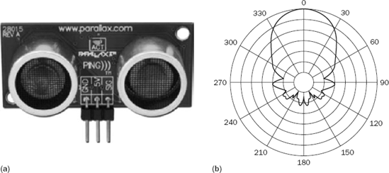
It might seem like sonar is a much better option than IR; but as with all sensors, sonar has several deficiencies and failure modes. Because a sonar beam is based on sound, it spreads out in a cone shape the farther it travels from the sensor. This means that a reading only gives an indication of the closest obstacle within an arc of several degrees (up to 60 degrees in the right image in Figure 13-12), and it is not possible to tell the exact direction to an obstacle. Some materials can also absorb sound, so there might not be sufficient reflection to get a reading. Lastly, if the sensor is at an angle to a wall, then it is possible for the reflection off the wall to bounce away from the sensor, not back toward it. In this case, the sensor records a maximum range value, which is a "miss." Obviously, this is a serious problem if the robot then charges ahead at full speed thinking that nothing is there!
Sonar sensors are usually arranged in a sonar ring, equally spaced around the robot, often with 12 or even 24 sensors. They can't be located too close together because of "cross-talk" between the sensors—that is, one sensor sees the reflection of the signal from a different sensor and therefore registers the wrong range.
MRDS does have a generic sonar contract, but the latest version of the LEGO NXT services uses the analog sensor contract for the LEGO sonar sensor.
Much of the recent research into robotics has used laser range finders (LRFs), which are far more accurate and have a much larger range compared to IR or sonar. However, a LRF costs thousands of dollars, whereas a sonar sensor costs less than $50.
A LRF uses a low-power laser beam, which is often a red beam, but newer devices use infrared. The LRF scans the beam across a wide arc using a rotating mirror and captures a range scan consisting of an array of measurements at fixed angles, often one degree apart.
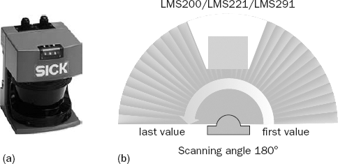
Typical LRFs have maximum ranges from 8m to over 100m and they usually have a field of view (the spread from first value to last value on the right in Figure 13-13) between 100 and 180 degrees. The SICK LMS200 LRF, shown on the left in Figure 13-13, is a popular model. Although it is very expensive compared to IR or sonar sensors, it is highly accurate, with a 180° field of view, resolution of 10mm ±15mm, and a maximum range of 10m.
The simulated Pioneer 3DX robot has a LRF and you can see red dots appearing on obstacles a couple of times per second. With a range of 10m or more, a LRF in an indoor environment can nearly always see obstacles. Only long corridors result in a maximum range reading being returned.
The Boe-Bot kit comes with a couple of light-dependent resistors (or photoresistors). These detect the amount of light falling on them, and their resistance varies accordingly. When incorporated into a circuit, they can be used to build a robot that either seeks out light (a photovore) or avoids light (a photophobe). With appropriate programming, the robot can be made to follow a flashlight or hide in the shadows like a cockroach.
The LEGO Mindstorms NXT kit also includes a light sensor, which incorporates an LED that can be turned on to illuminate the target so it can operate in either a passive mode (using ambient light) or an active mode. A color sensor is also available, which uses colored LEDs to illuminate the target and return a number that represents a code for the particular color.
Cameras have become popular input devices in recent years as the price of digital camera sensors has dropped dramatically and the resolution has continued to increase. MRDS supports both Internet Protocol (IP) cameras and webcams (which usually attach via a USB connection). Image sensors provide an array of pixel values whereby each pixel usually consists of red, green, and blue (RGB) components.
In effect, a camera is the equivalent of thousands or millions of individual light sensors. In Chapter 12, downward-facing simulated webcams are used as light sensors for the line-following example by averaging small areas of the input images and coming up with values for "lightness." In reality, nobody would waste a webcam for this task because it can be done with much cheaper sensors.
Processing video images is a complex task. It is not easy to obtain range measurements from a video image because of factors such as perspective. Cameras have therefore tended to be used to recognize objects, people, and places by performing what is called feature (or blob) extraction. For instance, robot soccer relies on the soccer ball being a bright color, like orange, so that the robot can easily locate it in the image. (See the FollowBall example in Chapter 12.) Using blob tracking, the robot can then follow the ball. MRDS V1.5 includes sample calibration and blob-tracking services.
The simulated Pioneer robot has a camera mounted on top of it. You can see the view from this camera by pressing F8 in the simulation window or selecting it from the Camera menu. If you use the Dashboard or TeleOperation services (located in the ProMRDSChapter4 folder), then you can select the camera from the list of services and the video will be displayed in a separate window that automatically maintains the correct aspect ratio. This Dashboard also works with real webcams if you include a Webcam service with your robot.
If you are interested in computer vision, you should download RoboRealm (www.roborealm.com). It works with MRDS and is fairly easy to set up.
Several other types of sensors are commonly used on robots. This is not a complete list, but it does provide some idea of what is available. Many of these sensors are available for the LEGO NXT, which is why they have been included here.
A GPS (global positioning system) sensor provides an estimate of the robot's location to within an area of several meters. Unfortunately, the signals from the GPS satellites are extremely weak, so a GPS receiver does not work indoors. Moreover, the accuracy of the position fixes is so poor that the robot might believe that it is in the room next door. MRDS includes services for the Microsoft GPS.
The robot's orientation is one of the most important pieces of information for navigation. If the robot becomes disoriented, either by bumping into obstacles or due to wheel slippage, then it can quickly become lost. A compass is valuable because it provides an absolute reference, i.e., errors do not accumulate over time.
Compass sensors work off the Earth's magnetic field. The HiTechnic compass sensor (www.hitechnic.com) for the LEGO NXT can measure bearings to the nearest degree, but the NXT only uses a single byte to represent analog values, so the readings are divided by two, resulting in a resolution of two degrees. The compass sensor can be read in the same way as an Ultrasonic (sonar) sensor because it just provides an analog value.
Just like a real compass, a compass sensor can be affected by large metallic objects and magnetic interference caused by motors and computers. Therefore, the compass sensor must be placed some distance from the LEGO NXT motors and even the NXT "brick." (The Tribot shown in Figure 13-3 has a compass mounted on a "stalk" at the back of the robot for this reason.) A compass must also be kept level or it produces incorrect readings. The effectiveness of compasses is reduced indoors, but they do work inside most buildings.
Acceleration/tilt sensors can be used to measure changes in speed and orientation. This type of sensor is available for the LEGO NXT (from LEGO or HiTechnic). Tilt sensors are useful to determine whether the robot is driving uphill, or for a legged robot to realize when it has fallen over so that it can get up again.
Sound sensors vary in their capabilities. Because sounds can contain high frequencies, it is not usually feasible to measure them in real time if the robot is remotely controlled. Therefore, sound sensors tend to produce an output that is proportional to the volume of noise, or they selectively filter (listen for) particular frequencies.
Obviously, a microphone is a form of sound sensor, but it requires a high sampling rate to obtain useful information. Microsoft provides a Speech Recognition service as part of MRDS V1.5. For this to work, the microphone must be attached to the PC running MRDS, not to the robot if it is remotely controlled. Of course, if there is a PC on the robot and it has sufficient processing power, then it might be able to do both speech recognition and speech synthesis—that is, it could actually talk to you!
A wheel encoder measures rotations of a wheel so that you can determine how far a robot has traveled, assuming that you know the radius of the wheels. Wheel encoders are usually rated in terms of the number of "ticks" per revolution of the wheel. An encoder might give 1200 ticks per rotation, or even 3600 ticks. The encoders built into the LEGO NXT motors, however, can only measure 360 ticks per revolution, or, even worse, in low-resolution mode only 9 ticks.
Wheel encoders, also sometimes called odometers, are notoriously unreliable. If you rely only on input from wheel encoders to keep track of your position, a process called dead reckoning, then you will invariably get lost. This happens because the wheels slip against the ground as the robot moves; it bumps into objects, which makes the wheels jump off the ground momentarily; or a variety of other reasons.
However, wheel encoders are essential if you expect to make accurate turns using the RotateDegrees request for a Differential Drive service, or move precise distances using DriveDistance. Even then, the small errors that occur on each request will accumulate over time.
Actuators are output devices that affect either the robot or the real world in some way. The obvious examples are motors (and wheels) that enable robots to drive around. Robotic arms have grippers to pick up objects. A bomb-disposal robot might have a rifle to shoot bombs, although you might imagine that this actuator would only ever be used once.
The main point about actuators is that they have an operating range: motors have a maximum speed; joints have minimum and maximum bend, or rotation angles; and so on.
You are probably familiar with electric motors that run continuously when power is applied to them. By adjusting the voltage, the speed of the motor can be varied. Reversing direction requires the polarity of the power to be reversed.
Motor control is usually done using a circuit board called an H-bridge. This board must be able to handle the large currents, sometimes several amps, that are necessary to drive a motor. In contrast, the typical circuitry inside a computer operates at a low voltage (5V or 3.3V) and low current (a few milliamps or even less). The H-bridge, therefore, translates the small signals from the computer to much larger signals for the motors, and it can also handle polarity reversals.
Servo motors are designed to move to a particular position and then hold that position. The position information is encoded in the signal sent to the servo motor. Typical servos operate on a pulse width modulation (PWM) system, with pulses being repeated 50 times per second. As long as the servo is receiving pulses, it resists any change to its position, which effectively locks it in place. This makes servos perfect for use in a robotic arm that has to lift loads of different weights, or for grippers.
A servo has an internal encoder to measure the angle of the motor shaft. This is usually a potentiometer. Most servos operate over a range from −90 degrees to +90 degrees and have physical stops at the extremes of their travel. Trying to drive a cheap servo beyond its range can damage it.
Just to confuse you, some hobby robots use servo motors for the wheels. By deliberately disabling the positional feedback circuit inside the motor, it can be made to rotate continuously (always searching for the desired position). The Boe-Bot uses continuous rotation servos. There are many advantages to using a small servo motor instead of a conventional electric motor, including cost and lower rotational speed.
Some types of actuators take a binary signal, such as light-emitting diodes (LEDs) or buzzers. You can turn these actuators on or off.
MRDS includes support to play WAV files. However, this only works on devices (such as PCs) that can handle WAV files and have an audio system capable of playing different frequencies of sound. Even if your robot does not have audio capability, you might still want to use sounds in your program to alert the user. Remember that the program is likely to be running on a PC that is remotely controlling the robot.
One unusual form of actuator is the Microsoft Text to Speech service. This can be used to add a voice to your robot, but the output plays on the PC controlling the robot, not the robot itself (unless it has an onboard PC).
As mentioned previously, PID controllers are very popular for process control. These controllers have a set point, i.e., a desired value of the system output, and the objective is to hold that value as closely as possible. The controller calculates the difference between the desired value and the current value of the output (which is the error), and adjusts the input accordingly. In the case of a motor, the objective might be to run at a constant speed, so the set point is the specified speed (which can be changed as necessary).
Figure 13-14 shows a simplified closed-loop control system where the controller is not onboard the actual robot. The controller can issue commands to the robot and it receives sensor information. On the basis of this feedback, the controller calculates an updated value for the output and the loop continues in this fashion. Eventually the error should reach zero and the output will remain steady.
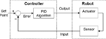
In Figure 13-14, the output to the actuator could be a power setting for a drive motor. The sensor in this case would be a wheel encoder, which measures rotations of the wheel. Wheel encoders are usually rated in terms of the number of "ticks" per revolution of the wheel. By counting ticks, the wheel speed can be determined.
The proportional component of the PID algorithm multiplies the error by a factor, called the proportional gain, so that the output is driven toward the desired value as quickly as possible. However, there is one problem with proportional control on its own—it often results in some residual offset from the desired value. (A discussion of the reason for this is beyond the scope of this chapter.)
Integral control involves integrating the error over time. Again there is a multiplying factor for the gain. (In process control, this factor is often expressed as a time constant, but this is not important here.) Integration can easily be performed by keeping a running sum of the errors each time through the control loop. Note that the error can be positive or negative. One effect of integral control is to cause the output to oscillate around the set point until the error is eventually reduced to zero.
To try to make the output settle quickly, differential control multiplies the derivative of the error by a gain factor (also sometimes expressed as a time constant). The objective is to have a damping effect. Calculating the derivative of a signal is easy if the sensor updates arrive at a regular time intervals—you simply subtract the previous value from the new value and divide by the time interval. It is not even necessary to divide by the time interval if it is constant because it can simply be lumped into the differential gain factor.
To avoid being overly sensitive, most controllers have a small dead zone—an acceptable threshold for the error below which no changes are made to the signal sent to the actuator. Without a dead zone, an actuator tends to jitter or hunt around the correct value.
Even though the diagram in Figure 13-14 shows the PID controller separate from the robot, in practice this is not a good idea. If the communication between the controller and the robot is over a slow connection, there is a delay in obtaining the feedback from the sensor. This delay has a destabilizing effect on the control loop. If it is too long, it causes oscillations, which might increase in magnitude and eventually be catastrophic. This is a classic problem in control theory when the system being controlled has inherent delays. It is quite obvious that if the feedback signal is sufficiently out of phase with the controller output, then the calculated value of the error will be wrong.
Fast feedback is also important for fundamental operations such as DriveDistance and RotateDegrees that are defined for the DifferentialDrive service. These operations enable the robot to be moved precisely. For this reason, they might be implemented onboard the robot, rather than remotely.
PID control is applicable if you are trying to control an analog quantity. However, some control schemes are based on digital inputs, so they use Boolean logic. For example, the Boe-Bot has two IR sensors and two "whiskers." Both of these are the equivalent of contact sensors, even though the IR sensor triggers without physical contact. The logic for avoiding obstacles is therefore very simple.
If you want to see how this is implemented on the Boe-Bot, go to the MRDS directory in Windows Explorer and navigate to samplesplatformsParallax and open BASICStamp2.sln. Once Visual Studio has started, open BoeBotControl.cs from the Solution Explorer. Locate the ExecuteMain routine. (You can select it from the drop-down list of class members.) Inside this routine you should find code similar to the following.
The first part of the code checks the whiskers (wLeft and wRight) to determine whether they have been triggered. Depending on which combination of whiskers has been depressed, the robot is sent a pre-defined command to execute backup, turn left, or turn right behavior. (The monitor program running on the Boe-Bot understands these commands and executes the necessary moves.)
if (_autonomousMode)
{
    if (wFlag)
    {
        if (wLeft && wRight)
        {
            Maneuver('U'),
        }
        else if (!wLeft && wRight)
        {
            Maneuver('L'),
        }
        else if (wLeft && !wRight)
        {
            Maneuver('R'),
        }
    }
The next section of code checks the IR sensors (irLeft and irRight) to determine whether either of them has registered an obstacle. The logic is basically the same as for the whiskers, except that if no IR sensors have been triggered, then the robot moves forward, which causes it to keep wandering around. If a sensor is triggered, then the robot turns in an arc rather than turning on the spot as it does when a whisker is triggered:
if (irFlag)
    {
        if (irLeft && irRight)
        {
            autonDir = AutonomousDirection.BKWD;
        }
        else if (!irLeft && irRight)
        {
            autonDir = AutonomousDirection.LEFT;
        }
        else if (irLeft && !irRight)
        {
            autonDir = AutonomousDirection.RIGHT;
        }
        else
        {
            autonDir = AutonomousDirection.FWD;
        }
The last part of the code sets the speed of the motors. (In this implementation, 0 means full-speed clockwise, 200 is full-speed counterclockwise, and 100 is stopped. These values are interpreted by code running on the Boe-Bot, as covered earlier in this chapter. Note that the motors are mounted with their shafts facing in opposite directions, so you have to rotate them in opposite directions to drive in a straight line.)
switch (autonDir)
        {
            case AutonomousDirection.FWD:
                {
                    pwmLeft = 200;
                    pwmRight = 0;
                } break;

            case AutonomousDirection.LEFT:
                {
                    pwmLeft = 0;
                    pwmRight = 0;
                } break;

            case AutonomousDirection.RIGHT:
                {
                    pwmLeft = 200;
                    pwmRight = 200;
                } break;

            case AutonomousDirection.BKWD:
                {
                    pwmLeft = 0;
                    pwmRight = 200;
                } break;
        }
        SendSpeed(pwmLeft, pwmRight);
    }
}
This type of control can be described in words, or behaviors, rather than mathematical equations (like a PID controller)—for example, "if you see an obstacle on the left, veer to the right." The exact definition of "veer" is up to the programmer, and choosing different values will make the robot behave differently. For example, if the programmer were paranoid and interpreted "veer" to mean "turn around and run away" then you would have a very shy robot.
Obviously, the variety of possible controllers is very large. A significant part of the effort in programming a robot is creating the control strategies and algorithms to make it perform the desired tasks, and then testing this code. Quite often, unexpected "emergent behaviors" appear when you combine a variety of different algorithms.
This chapter covered some of the basics of robotics hardware and outlined some of the robots that are available on the market and supported by MRDS. Depending on your finances, choose a robot or two, or perhaps you have been given a robot to work with. In any case, you should find that it falls into one of the categories listed in this chapter. Support under MRDS might be provided by Microsoft or the hardware vendor.
It is important to understand that Microsoft Robotics Developer Studio is a framework or platform for running robots. Microsoft makes the analogy between the Windows operating system for a PC and MRDS for a robot. In the same way that Windows requires each brand of PC to implement the standard BIOS calls for low-level hardware access, MRDS needs some low-level drivers. Microsoft does not intend to support every robot on the market—that will be left to the manufacturers of the different robots. If the robot is not supported, you need to write the services yourself. This is not a trivial task and it is not advisable for a novice roboticist to embark on this path.
The next few chapters demonstrate how to use several real robots, culminating in the development of new services for a robot.