
54.2. Application Designer
The Application Diagrams will be used to configure and connect applications to each other. To create one, you can select File ![]() New Project, and in the Distributed System Diagram choose Application Diagram. This will create a new solution with the Application Diagram. If you are starting with an existing solution, you can right-click it and choose Add
New Project, and in the Distributed System Diagram choose Application Diagram. This will create a new solution with the Application Diagram. If you are starting with an existing solution, you can right-click it and choose Add ![]() New Distributed System Diagram. This will look for projects you have in your solution and add them to the Application Diagram if those projects are compatible with the application types available.
New Distributed System Diagram. This will look for projects you have in your solution and add them to the Application Diagram if those projects are compatible with the application types available.
From the Toolbox you have three categories. The first one, General Designer, is available for all the diagrams and includes the connection tool and comments. The Applications category includes application prototypes that will map to projects in your solution. You have eight types of applications. The Endpoints represent connection points between applications, and these are specific for the different prototypes — for example, you can use only a Web Content and .NET Web Service Endpoint in applications mapping to web sites or web applications.
You can extend the Application Designer to include custom application prototypes. Please see "Extending Distributed System Designers" on MSDN.
For this case study you will start with a new solution and a new Application Diagram. Figure 54-1 shows the final result. We added a generic application to represent the Manufacturing system. The SAP Services and Corporate Directory are modeled as external web services, and when you add them you need to specify their WSDLs to define their endpoints. This is needed because the Application Designer will use it to create proxies for applications connecting to them. There's more behind these three pieces, but for this solution we only care about their interfaces — that's why we don't model the databases or other services used by this application.
Figure 54.1. Figure 54-1
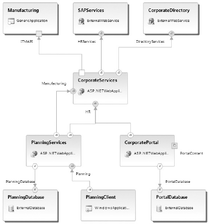
In the center we have a CorporateServices application modeled as an ASP.NET Web Application. It has consumer endpoints for the three applications we mentioned and has two provider endpoints that are consumed by the PlanningServices and the CorporatePortal. The PlanningServices application will connect to this database and provide services for the PlanningClient.
We can compare ADs to UML Component diagrams. You can think of endpoints as interfaces and applications as components, but the difference is that the AD will map directly to implementation concepts. You have the option to implement a specific application or all the applications defined in the diagram; when you do this, Visual Studio will create projects in the solution based on the selected template, proxies for its web service consumer endpoints, and web services for the web service provider endpoints. It will add a connection string to the configuration file for each database consumer endpoint. Other settings, specified in the Settings and Constraints Editor (described later), are also included in the config files. There are some prototypes that can't be implemented; for example, the external web services and the generic application we used are only references for the rest of our application.
Before implementing the projects you can change their names by selecting them and then making changes in the properties tool window. By default it will have the same name as the application. All applications are set to use Visual Basic, but you can change this from this window. You can also select a template to implement the prototype. For example, by default Visual Studio will use a WinForms project to implement your Windows application, but we chose to use a custom template and selected WPF. You can change other things like the namespace and framework version. Figure 54-2 shows the Solution Explorer with the applications implemented. As you can see, our PlanningClient was implemented using a WPF project, and a proxy for the planning endpoint was created.
Figure 54.2. Figure 54-2

For your web services provider endpoints you can define operations, similar to the way you add methods to a class in the Class Designer as you saw in Chapter 18. From the Properties window you can add attributes specific to web methods, like SOAP Action, Cache Duration, and Enable Session.