
Chapter 3. Your First Embedded Program
ACHTUNG! Das machine is nicht fur gefingerpoken und mittengrabben. Ist easy schnappen der springenwerk, blowenfusen und corkenpoppen mit spitzensparken. Ist nicht fur gewerken by das dummkopfen. Das rubbernecken sightseeren keepen hands in das pockets. Relaxen und vatch das blinkenlights!
In this chapter, we’ll dive right into embedded programming by way of an example. Our example is similar in spirit to the “Hello, World!” example found in the beginning of most other programming books. We’ll discuss why we picked this particular program and point out the parts of it that are dependent on the target hardware. This chapter contains only the source code for the program. We’ll discuss how to create the executable and how to actually run it in the chapters that follow.
Hello, World!
It seems that every programming book ever written begins with the same example—a program that prints “Hello, World!” on the user’s screen. An overused example such as this might seem a bit boring. Among other things, the example helps readers quickly assess the ease or difficulty with which simple programs can be written in the programming environment at hand. In that sense, “Hello, World!” serves as a useful benchmark for users of programming languages and computer platforms.
Based on the “Hello, World!” benchmark, embedded systems are among the most challenging computer platforms for programmers to work with. In some embedded systems, it might even be impossible to implement the “Hello, World!” program. And in those systems that are capable of supporting it, the printing of text strings is usually more of an endpoint than a beginning.
A principal assumption of the “Hello, World!” example is that there is some sort of output device on which strings of characters can be printed. A text window on the user’s monitor often serves that purpose. But most embedded systems lack a monitor or analogous output device. And those that do have one typically require a special piece of embedded software, called a display driver, to be implemented first—a rather challenging way to begin one’s embedded programming career.
It would be much better to begin with a small, easily implemented, and highly portable embedded program in which there is little room for programming mistakes. After all, the reason our book-writing counterparts continue to use the “Hello, World! example is that implementing it is a no-brainer. This eliminates one of the variables in the case that the user’s program doesn’t work correctly the first time: it isn’t a bug in his code; rather, it is a problem with the development tools or process he used to create the executable program.
Embedded programmers must be self-reliant. They must always begin
each new project with the assumption that nothing works—that all they
can rely on is the basic syntax of their programming language. Even the
standard library routines might not be available to them. These are the
auxiliary functions—such as printf
and memcpy—that most other
programmers take for granted. In fact, library routines are often as
much a part of the C-language standard as the basic syntax. However, the
library part of the standard is more difficult to support across all
possible computing platforms and is occasionally ignored by the makers
of compilers for embedded systems.
So, you won’t find an actual “Hello, World!” program in this
chapter. Instead, we’ll write the simplest C-language program we can,
without assuming you have specialized hardware (which would require a
device driver) or any library with functions such as printf. As we progress through the book, we
will gradually add standard library routines and the equivalent of a
character output device to our repertoire. By that time, you’ll be well
on your way to becoming an expert in the field of embedded systems
programming.
The Blinking LED Program
Almost every embedded system that we’ve encountered in our respective careers has had at least one LED that could be controlled by software. If the hardware designer plans to leave the LED out of the circuit, lobby hard for getting one attached to a general-purpose I/O (GPIO) pin. As we will see later, this might be the most valuable debugging tool you have.
A popular substitute for the “Hello, World!” program is one that blinks an LED at a rate of 1 Hz (one complete on-off cycle per second). [1] Typically, the code required to turn an LED on and off is limited to a few lines of code, so there is very little room for programming errors to occur. And because almost all embedded systems have LEDs, the underlying concept is extremely portable.
Our first step is to learn how to control the green LED we want to toggle. On the Arcom board, the green LED is located on the add-on module shown in Figure 3-1. The green LED is labeled “LED2” on the add-on module. The Arcom board’s VIPER-Lite Technical Manual and the VIPER-I/O Technical Manual describe how the add-on module’s LEDs are connected to the processor. The schematics can also be used to trace the connection from the LED back to the processor, which is typically the method you need to use once you have your own hardware.
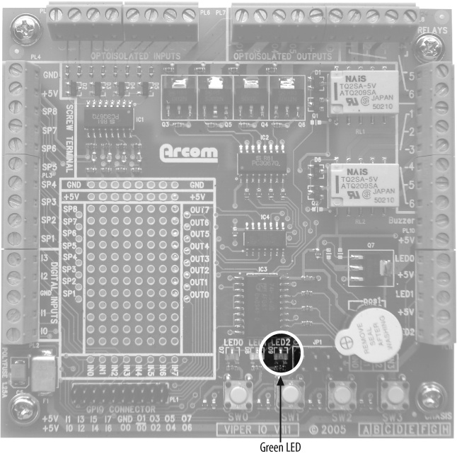
LED2 is controlled by the signal OUT2, as described in the LEDs section in the Arcom board’s VIPER-I/O Technical Manual. This text also informs us that the signals to the LEDs are inverted; therefore, when the output is high, the LEDs are off, and vice versa. The general-purpose I/O section of the VIPER Technical Manual shows that the OUT2 signal is controlled by the processor’s GPIO pin 22. Therefore, we will need to be able to set GPIO pin 22 alternately high and low to get our blinker program to function properly.
The superstructure of the Blinking LED program is shown next. This
part of the program is hardware-independent. However, it relies on the
hardware-dependent functions ledInit,
ledToggle, and delay_ms to initialize the GPIO pin
controlling the LED, change the state of the LED, and handle the timing,
respectively. These functions are described in the following sections,
where we’ll really get a sense of what it’s like to do embedded systems
programming.
#include "led.h"

/**********************************************************************
 *
 * Function:    main
 *
 * Description: Blink the green LED once a second.
 *
 * Notes:
 *
 * Returns:     This routine contains an infinite loop.
 *
 **********************************************************************/
int main(void)
{
    /* Configure the green LED control pin. */
    ledInit();

    while (1)
    {
        /* Change the state of the green LED. */
        ledToggle();

        /* Pause for 500 milliseconds. */
        delay_ms(500);
    }

    return 0;
}
The ledInit Function
Before we start to use a particular peripheral, we first need to understand the hardware used to control that specific peripheral. [2] Because the LED we want to blink is connected to one of the PXA255 processor’s 85 bidirectional GPIO pins, we need to focus on those. Often, as is the case with the PXA255 processor, I/O pins of embedded processors have multiple functions. This allows the same pins either to be used as user-controllable I/O or to support particular peripheral functionality within the processor. Configuration registers are used to select how the application will use each specific port pin.
On the PXA255, each port pin can be configured for use by the internal peripheral (called an alternate-function pin) or by the user (called a general-purpose pin). For each GPIO pin, there are several 32-bit registers. These registers allow for configuration and control of each GPIO pin. The description of the registers for the GPIO port that contains the pin for the green LED is shown in Table 3-1. These registers are located within the PXA255 chip.
| Register name | Type | Address | Name | Purpose |
| GPLR0 | Read-only | 0x40E00000 | GPIO Pin-Level Register | Reflects the state of each GPIO pin.0 = Pin state is low.1 = Pin state is high. |
| GPDR0 | Read/write | 0x40E0000C | GPIO Pin Direction Register | Controls whether a pin is an input or output.0 = Pin is configured as an input.1 = Pin is configured as an output. |
| GPSR0 | Write-only | 0x40E00018 | GPIO Pin Output Set Register | For pins configured as output, the pin is set high by writing a 1 to the appropriate bit in this register.0 = Pin is unaffected.1 = If configured as output, pin level is set high. |
| GPCR0 | Write-only | 0x40E00024 | GPIO Pin Output Clear Register | For pins configured as output, the pin is set low by writing a 1 to the appropriate bit in this register.0 = Pin is unaffected.1 = If configured as output, pin level is set low. |
| GAFR0_U | Read/write | 0x40E00058 | GPIO Alternate Function Register (High) | Configures GPIO pins for general I/O or alternate functionality.00 = GPIO pin is used as general-purpose I/O. 01 = GPIO pin is used for alternate function 1. 10 = GPIO pin is used for alternate function 2. 11 = GPIO pin is used for alternate function 3. |
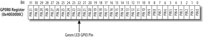
The PXA255 Processor Developer’s Manual states that the configuration of the GPIO pins for the LEDs are controlled by bits 20 (red), 21 (yellow), and 22 (green) in the 32-bit GPDR0 register. Figure 3-2 shows the location of the bit for GPIO pin 22 in the GPDR0 register; this bit configures the direction of GPIO pin 22 that controls the green LED.
The PXA255 peripheral control registers are located in memory space, as shown in Figure 2-6 in Chapter 2. The addresses of these registers are given in Table 3-1. Because the registers are memory-mapped, they are easily accessed in C in the same ways that any memory location is read or written.
Tip
You may notice as you read through the PXA255 Processor Developer’s Manual that certain registers contain bits that are designated as reserved. This is typical in many registers within a processor. The processor manual will state how these bits should be read or written. In the case of the PXA255 processor, the manual states that reserved bits must be written as zeros and ignored when read. It is important that you do not use for other purposes any bits labeled as reserved.
Most registers within a CPU have a default configuration after reset. This means that before we are able to control the output on any I/O pins, we need to make sure the pin is configured properly. After reset, all GPIO pins in the PXA255 are configured as inputs. In addition, they function as general-purpose I/O pins rather than alternate-function pins.
Warning
Although the GPIO pins that control the LEDs are configured as general-purpose I/O pins upon reset, we need to ensure that the other software that is running did not change the functionality of these GPIO pins.
It is a good practice always to initialize hardware you are going to use, even if you think the default behavior is fine.
In our case, we need to configure GPIO pin 22 as an output via bit 22 in the GPDR0 register. Furthermore, the GPIO pin that controls the green LED must be set to function as a general-purpose I/O pin via the same bit in the GAFR0_U register.
The bitmask for the GPIO pin that controls the green LED on the Arcom board is defined in our program as:
#define LED_GREEN (0x00400000)
A fundamental technique used by the ledInit routine is a read-modify-write of a
hardware register. First, read the contents of the register, then
modify the bit that controls the LED, and finally write the new value
back into the register location. The code in ledInit performs two read-modify-write
operations—one on the register GAFR0_U and one on GPDR0, in that
order. These operations are done by using the C language &= and |= operators, respectively; the effect of
x &= y
is the same as that of x = x
& y. We will take a closer look at these
operators and bit manipulation in Chapter 7.
The ledInit function
configures the PXA255 processor on the Arcom board to control the
green LED located on the add-on module. In the following code, you may
notice that we clear the GPIO pin in the GPCR0 register to ensure that
the output voltage on the GPIO pin is first set to zero, as suggested
in the developer’s manual.
#define PIN22_FUNC_GENERAL          (0xFFFFCFFF)

/**********************************************************************
 *
 * Function:    ledInit
 *
 * Description: Initialize the GPIO pin that controls the LED.
 *
 * Notes:       This function is specific to the Arcom board.
 *
 * Returns:     None.
 *
 **********************************************************************/
void ledInit(void)
{
    /* Turn the GPIO pin voltage off, which will light the LED. This should
     * be done before the pins are configured. */
    GPIO_0_CLEAR_REG = LED_GREEN;

    /* Make sure the LED control pin is set to perform general
     * purpose functions. RedBoot may have changed the pin's operation. */
    GPIO_0_FUNC_HI_REG &= PIN22_FUNC_GENERAL;

    /* Set the LED control pin to operate as output. */
    GPIO_0_DIRECTION_REG |= LED_GREEN;
}
The ledToggle Function
This routine runs within an infinite loop and is responsible for changing the state of the LED. The state of this LED is controlled by writing to either the GPIO Pin Output Set Register (GPSR) or the GPIO Pin Output Clear Register (GPCR). The GPSR0 register allows us to set the level of the LED control GPIO pin high; the GPCR0 register allows us to set the level of the LED control GPIO pin low. Writing to bit 22 of these registers changes the voltage on the external pin and, thus, the state of the green LED. Because the GPIO pin to the LED is inverted, when bit 22 of the GPSR0 register is set, the green LED is off, whereas when bit 22 of the GPCR0 register is set, the green LED is on. The state of the LED is determined by the GPIO Pin Level Register (GPLR).
As described earlier, the PXA255 processor has separate
write-only registers for setting (GPSR0) and clearing (GPCR0) the bit
that controls the GPIO pin. Therefore, a read-modify-write cannot be
used to toggle the state of the LED. The actual algorithm of the
ledToggle routine is
straightforward: determine the current state for the LED of interest
and write into the GPIO register the bit that controls that LED in
order to set the new state of the LED.
/**********************************************************************
 *
 * Function:    ledToggle
 *
 * Description: Toggle the state of one LED.
 *
 * Notes:       This function is specific to the Arcom board.
 *
 * Returns:     None.
 *
 **********************************************************************/
void ledToggle(void)
{
    /* Check the current state of the LED control pin. Then change the
     * state accordingly. */
    if (GPIO_0_LEVEL_REG & LED_GREEN)
        GPIO_0_CLEAR_REG = LED_GREEN;
    else
        GPIO_0_SET_REG = LED_GREEN;
}
The delay_ms Function
We also need to implement a 500 ms delay between LED toggles. We
do this by busy-waiting within the following delay_ms routine. This routine accepts the
length of the requested delay, in milliseconds, as its only parameter.
It then multiplies that number by the constant CYCLES_PER_MS to obtain the total number of
while-loop iterations that are required in order to delay for the
requested time period:
/* Number of decrement-and-test cycles. */
#define CYCLES_PER_MS               (9000)

/**********************************************************************
 *
 * Function:    delay_ms
 *
 * Description: Busy-wait for the requested number of milliseconds.
 *
 * Notes:       The number of decrement-and-test cycles per millisecond
 *              was determined through trial and error.  This value is
 *              dependent upon the processor type, speed, compiler, and
 *              the level of optimization.
 *
 * Returns:     None.
 *
 **********************************************************************/
void delay_ms(int milliseconds)
{
    long volatile cycles = (milliseconds * CYCLES_PER_MS);

    while (cycles != 0)
        cycles--;
}
The hardware-specific constant CYCLES_PER_MS represents the number of times
the processor can get through the while loop in a millisecond. To
determine this number, we used trial and error. We will see later how
to use a hardware counter to achieve better timing accuracy.
The four functions main,
ledInit, ledToggle, and delay_ms do the whole job of the Blinking
LED program. Of course, we still need to talk about how to build and
execute this program. We’ll examine those topics in the next two
chapters. But first, we have a little something to say about infinite
loops and their role in embedded systems.
The Role of the Infinite Loop
One of the most fundamental differences between programs developed for embedded systems and those written for other computer platforms is that the embedded programs almost always have an infinite loop. Typically, this loop surrounds a significant part of the program’s functionality, as it does in the Blinking LED program. The infinite loop is necessary because the embedded software’s job is never done. It is intended to be run until either the world comes to an end or the board is reset, whichever happens first.
In addition, most embedded systems run only one piece of software. Although hardware is important, the system is not a digital watch or a cellular phone or a microwave oven without that software. If the software stops running, the hardware is rendered useless. So the functional parts of an embedded program are almost always surrounded by an infinite loop that ensures that they will run forever.
If we had forgotten the infinite loop in the Blinking LED program, the LED would have simply changed state once.
[1] Of course, the rate of blink is completely arbitrary. But one of the good things about the 1 Hz rate is that it’s easy to confirm with a stopwatch. Simply start the stopwatch, count off a number of blinks, stop the stopwatch, and see whether the number of elapsed seconds is the same as the the number of blinks you counted. Need greater accuracy? Simply count off more blinks.
[2] All of the documentation for the Arcom board is contained on the VIPER-Lite Development Kit CD-ROM. This includes datasheets and user’s manuals for the components on the board.