Chapter 7. Peripherals
Each pizza glides into a slot like a circuit board into a computer, clicks into place as the smart box interfaces with the onboard system of the car. The address of the customer is communicated to the car, which computes and projects the optimal route on a heads-up display.
In addition to the processor and memory, most embedded systems contain a handful of other hardware devices. Some of these devices are specific to each embedded system’s application domain, while others—such as timers/counters and serial ports—are useful in a wide variety of systems. The most commonly used devices are often included within the same chip as the processor and are called internal, or on-chip, peripherals. Hardware devices that reside outside the processor chip are, therefore, said to be external peripherals. In this chapter, we’ll discuss the most common software issues that arise when interfacing to a peripheral of either type.
Control and Status Registers
An embedded processor interacts with a peripheral device through a set of control and status registers. These registers are part of the peripheral hardware, and their locations, size, and individual meanings are features of the peripheral. For example, the registers within a serial controller are very different from those in a timer. In this section, we’ll describe how to manipulate the contents of these control and status registers directly from your C language programs.
As discussed in Chapter 2, depending upon the design of the processor and board, peripheral devices are located either in the processor’s memory space or within the I/O space. By far, the most common of the two types is memory-mapped peripherals, which are generally easier to work with.
Memory-mapped control and status registers can be made to look just like
ordinary variables. To do this, you need simply declare a pointer
to the register, or block of registers, and set the value of the pointer
explicitly. Example code from previous chapters has already demonstrated
access to peripheral registers, but let’s take a closer look at the
code. The GPIO registers in the PXA255 are memory-mapped so that
pointers to registers look just like a pointer to any other integer
variable. The following code declares the variable pGpio0Set as a pointer to a uint32_t—a 32-bit value representing the
device’s register—and explicitly initializes the variable to the address
0x40E00018. From that point on, the pointer to the register looks just
like a pointer to any other integer variable.
uint32_t *pGpio0Set = (uint32_t *)(0x40E00018);
Note, however, one very important difference between device registers and ordinary variables in local memory. The contents of a device register can change without the knowledge or intervention of your program. That’s because the register contents can also be modified by the peripheral hardware. By contrast, the contents of a variable in memory will not change unless your program modifies them explicitly. For that reason, we say that the contents of a device register are volatile, or subject to change without notice.
The keyword volatile should be
used when declaring pointers to device registers. This warns the compiler not
to make any assumptions about the data stored at that address. For
example, if the compiler sees a write to the volatile location followed
by another write to that same location, it will not assume that the
first write is an unnecessary use of processor cycles. And in the case
of reads, it will not assume that a second read of the same location
will return the same result, as it would with a variable.
Here’s an example that uses the keyword volatile to warn the compiler about the GPIO
Pin Output Set register. The goal of this function is to write the value
of the register at two different times, thereby setting two different
GPIO pins high at different times:
uint32_t volatile *pGpio0Set = (uint32_t volatile *)(0x40E00018);

void gpioFunction(void)
{
     /* Set GPIO pin 0 high. */
     *pGpio0Set = 1;                /* First write. */

     delay_ms(1000);

     /* Set GPIO pin 1 high. */
     *pGpio0Set = 2;                /* Second write. */
}
If the volatile keyword was not
used to declare the variable pGpio0Set, the optimizer would be permitted to
change the operation of the code. For example, the compiler might remove
the setting of pGpio0Set to 1 in the
previous code because the compiler can’t see any purpose to this
setting. If the compiler intervened in this manner, the GPIO pins would
not operate as the software developer intended. So the volatile keyword instructs the optimization
phase of the compilation to leave every change to a variable in place
and to assume that the variable’s contents cannot be predicted by
earlier states.
It would be wrong to interpret the declaration statement of
pGpio0Set to mean that the pointer
itself is volatile. In fact, the value of the variable pGpio0Set will remain 0x40E00018 for the
duration of the program (unless it is changed somewhere else, of
course). The data that is pointed to, rather, is subject to change
without notice. This is a very subtle point, and thinking about it too
much may confuse you. Just remember that the location of a register is
fixed, though its contents might not be. And if you use the volatile keyword, the compiler will assume the
same.
You might also notice that the pointer to the GPSR0 register is
declared as an unsigned integer. Registers sometimes consist of
several subfields, and almost all of the values are positive by
definition. For these reasons, embedded programmers typically use
unsigned integer types for peripheral
registers.
Tip
Signed integers may be needed when reading samples from an analog-to-digital converter (A/D converter or ADC).
Bit Manipulation
The C language bitwise operators can be used to manipulate the contents
of registers. These operators are & (AND), | (OR), ~
(NOT), ^ (XOR), << (left shift), and >> (right shift). The example code in
the following sections shows how to test, set, clear, and toggle
individual bits via a pointer to a timer status register called
pTimerStatus.
In this section, we’ll number the bits the way you need to think of them when creating masks. The least-significant bit is called bit 0, and it can be represented in a hexadecimal mask as 0x01; the most-significant bit in a byte is called bit 7, and it can be represented in a hexadecimal mask as 0x80.
Testing bits
The following code tests to see whether bit 3 is set in
the timer status register using the
& operator:
if (*pTimerStatus & 0x08)
{
    /* Do something here... */
}
In this case, we’ll imagine that the value in the timer status
register, contained in the variable pTimerStatus, is 0x4C; the & operator performs an AND operation
with 0x08. The operation looks like this:
        0 1 0 0 1 1 0 0 (0x4C)
AND (&)
        0 0 0 0 1 0 0 0 (0x08)
       =======================
        0 0 0 0 1 0 0 0 (0x08)
Because the proper bit is set in the register, the code enters
the if statement.
Setting bits
To set bit 4, the | operator is used as shown in the following
code:
*pTimerStatus |= 0x10;
resulting in:
        0 1 0 0 1 1 0 0  (0x4C)
OR (|)
        0 0 0 1 0 0 0 0  (0x10)
       =================
        0 1 0 1 1 1 0 0  (0x5C)
Clearing bits
The code to clear bit 2 uses the
& and ~ operators as follows:
*pTimerStatus &= ~(0x04);
For this operation, the inverse of 0x04 equals 0xFB. The
&= operator sets bit 2 of the
timer status register to 0, while leaving all other bits unchanged.
The operation looks like this:
        0 1 0 1 1 1 0 0  (0x5C)
AND (&)
NOT (~) 1 1 1 1 1 0 1 1  (0xFB)
       =================
        0 1 0 1 1 0 0 0  (0x58)
Note that all bits in the register remain the same except for the bit we want to clear.
Toggling bits
It is sometimes useful to change a bit back and forth.
For instance, you may want to blink an LED on and off. You may also
want to toggle a bit back and forth, without having to check it
first, and explicitly set or clear it. Toggling is done in C with
the ^ operator. Here is the code
to toggle bit 7 in the timer status register:
*pTimerStatus ^= 0x80;
This results in the following operation:
        0 1 0 1 1 0 0 0  (0x58)
XOR (^)
        1 0 0 0 0 0 0 0  (0x80)
       =================
        1 1 0 1 1 0 0 0  (0xD8)
Shifting bits
Another type of useful bitwise operation is a shift. For
example, consider what happens to the value of the 8-bit unsigned
integer bitCount that contains
0xAC and is shifted right by 1 bit. Code demonstrating a right shift
follows:
bitCount >>= 1;
This results in:
        1 0 1 0 1 1 0 0  (0xAC)
>> by 1
       =================
        0 1 0 1 0 1 1 0  (0x56)
In this case, a 0 is shifted in from the left. However, the C standard also allows the most significant bit to be repeated when the variable is signed. We recommend you use unsigned integers for variables on which you perform bit operations so that you will not have to worry about the different results on different compilers.
Assume the value of the 8-bit unsigned integer bitCount is again 0xAC and is shifted left
by 2 bits:
bitCount <<= 2;
This results in:
        1 0 1 0 1 1 0 0  (0xAC)
<< by 2
       =================
        1 0 1 1 0 0 0 0  (0xB0)
One reason to use a shift is if you want to perform an operation on each bit of a register in turn; you can create a bitmask (discussed in the next section) with 1 bit set or clear and shift it so you can operate on the individual bits of the register.
Bitmasks
A bitmask is a constant often used along with bitwise operators to manipulate one or more bits in a larger integer field. A bitmask is a constant binary pattern, such as the 16-bit hexadecimal literal 0x00FF, that can be used to mask specific bits. Bitmasks can be used with bitwise operators in order to set, test, clear, and toggle bits. Following are example bitmasks for the timer status register:
#define TIMER_COMPLETE              (0x08)
#define TIMER_ENABLE                (0xC0)
The bitmasks TIMER_COMPLETE
and TIMER_ENABLE are descriptive
names that correspond to specific bits in a peripheral’s register.
Using a symbolic (e.g., #define)
bitmask allows you to write code that is more descriptive and almost
self-commented. By replacing hexadecimal literals with words, the
definition makes it easier for you (or someone else) to understand
the code at a later time. Here is an example of a bitwise operation
involving a bitmask:
if (*pTimerStatus & TIMER_COMPLETE)
{
    /* Do something here... */
}Bitfields
A bitfield is a field of one or more bits
within a larger integer value. Bitfields are useful for bit
manipulations and are supported within a
struct by C language compilers.
struct
{
    uint8_t  bit0   : 1;
    uint8_t  bit1   : 1;
    uint8_t  bit2   : 1;
    uint8_t  bit3   : 1;
    uint8_t  nibble : 4;
} foo;
Bits within a bitfield can be individually set, tested, cleared, and toggled without affecting the state of the other bits outside the bitfield.
To test bits using the bitfield, use code such as the following:
if (foo.bit0)
{
    /* Do other stuff. */
}
Here’s how to test a wider field (such as two bits) using a bitfield:
if (foo.nibble == 0x03)
{
    /* Do other stuff. */
}
To set a bit using a bitfield, use this code:
foo.bit1 = 1;
And use code such as the following to set multiple bits in a bitfield:
foo.nibble = 0xC;
To clear a bit using the bitfield, use this code:
foo.bit2 = 0;
And to toggle a bit using the bitfield, use this:
foo.bit3 = ~foo.bit3; /* or !foo.bit3 */
There are some issues you must be aware of should you decide to use bitfields. Bitfields are not portable; some compilers start from the least significant bit, while others start from the most significant bit. In some cases, the compiler may require enclosing the bitfield within a union; doing this makes the bitfield code portable across ANSI C compilers.
In the following example, we use a union to contain the bitfield. In addition to making the bitfield code portable, the union provides wider register access.
union
{
    uint8_t byte;
    struct
    {
        uint8_t  bit0   : 1;
        uint8_t  bit1   : 1;
        uint8_t  bit2   : 1;
        uint8_t  bit3   : 1;
        uint8_t  nibble : 4;
    } bits;
} foo;
Instead of accessing only individual bits, the register can be written to as a whole. For example, the bitfield union, along with bitmasks, can be useful when initializing a register, as shown here:
foo.byte = (TIMER_COMPLETE | TIMER_ENABLE);
while individual bits are still accessible, as shown here:
foo.bits.bit2 = 1;
Bitmasks are more efficient than bitfields in certain instances. Specifically, a bitmask is usually a better way to initialize several bits in a register. For example, the following code initializes the timer status register by setting the two bits denoted by the macros and clearing all others:
*pTimerStatus = (TIMER_COMPLETE | TIMER_ENABLE);
Setting and clearing bits using a bitfield is no faster than
using a bitmask; with some compilers, it can be slower to use a
bitfield. One benefit of using bitfields is that individual
bitfields may be declared volatile or const. This is useful when a register is
writeable but contains a few read-only bits.
Struct Overlays
In embedded systems featuring memory-mapped I/O devices, it is sometimes useful to overlay a C struct onto each peripheral’s control and status registers. Benefits of struct overlays are that you can read and write through a pointer to the struct, the register is described nicely by the struct, code can be kept clean, and the compiler does the address construction at compile time.
The following example code shows a struct overlay for a timer
peripheral. If a peripheral’s registers do not align correctly,
reserved members can be included in the struct. Thus, in the following
example, an extra field that you’ll never refer to is included at
offset 4 so that the control field
lies properly at offset 6.
typedef struct
{
    uint16_t count;                 /* Offset 0 */
    uint16_t maxCount;              /* Offset 2 */
    uint16_t _reserved1;            /* Offset 4 */
    uint16_t control;               /* Offset 6 */
} volatile timer_t;

timer_t *pTimer = (timer_t *)(0xABCD0123);
Tip
Note that the individual fields of a struct, as well as the entire struct, can be declared volatile.
When you use a struct overlay to access registers, the compiler
constructs the actual memory-mapped I/O addresses. The members of the
timer_t struct defined in the
previous example have the address offsets shown in Table 7-1.
It is very important to be careful when creating a struct overlay to ensure that the sizes and addresses of the underlying peripheral’s registers map correctly.
The bitwise operators shown earlier to test, set, clear, and toggle bits can also be used with a struct overlay. The following code shows how to access the timer peripheral’s registers using the struct overlay. Here’s the code for testing bits:
if (pTimer->control & 0x08)
{
    /* Do something here... */
}
Here’s the code for setting bits:
pTimer->control |= 0x10;
Here’s the code for clearing bits:
pTimer->control &= ~(0x04);
And here’s the code for toggling bits:
pTimer->control ^= 0x80;
The Device Driver Philosophy
When it comes to designing device drivers, always focus on one easily stated goal: hide the hardware completely. This hiding of the hardware is sometimes called hardware abstraction. When you’re finished, you want the device driver module to be the only piece of software in the entire system that reads and/or writes that particular device’s control and status registers directly. In addition, if the device generates any interrupts, the interrupt service routine that responds to them should be an integral part of the device driver. The device driver can then present a generic interface to higher software levels to access the device. This eliminates the need for the application software to include any device-specific software. In this section, we’ll explain why this philosophy is universally accepted and how it can be achieved.
Attempts to hide the hardware completely are difficult. Any programming interface you select will reflect the broad features of the device. That’s to be expected. The goal should be to create a programming interface that would not need to be changed if the underlying peripheral were replaced with another in its general class. For example, all flash memory devices share the concepts of sectors (though the sector size may differ between chips). The following programming interface provided for a flash driver should work with any flash memory device:
void flashErase(uint32_t sector);
void flashWrite(uint32_t offset, uint8_t *pSrcAddr, uint32_t numBytes);
These two calls closely resemble the way all flash chips work in regard to reads and writes. An erase operation can be performed only on an entire sector. Once erased, individual bytes or words can be rewritten. But the interfaces here hide the specific features of the flash device and its functions from higher software levels, as desired.
Device drivers for embedded systems are quite different from their PC counterparts. In a general-purpose computer, the core of the operating system is distinct from the device drivers, which are often written by people other than the application developers. The operating system offers an interface that drivers must adhere to, while the rest of the system and applications depend on drivers doing so. For example, Microsoft’s operating systems impose strict requirements on the software interface to a network card. The device driver for a particular network card must conform to this software interface, regardless of the features and capabilities of the underlying hardware. Application programs that want to use the network card are forced to use the networking API provided by the operating system and don’t have direct access to the card itself. In this case, the goal of hiding the hardware completely is easily met.
By contrast, the application software in an embedded system can easily access the hardware. In fact, because all of the software is generally linked together into a single binary image, little distinction is made between the application software, operating system, and device drivers. Drawing these lines and enforcing hardware access restrictions are purely the responsibilities of the software developers. Both are design decisions that the developers must consciously make. In other words, the implementers of embedded software can more easily cheat on the software design than can their nonembedded peers.
The benefits of good device driver design are threefold:
Because of the modularity, the structure of the overall software is easier to understand. In addition, it is easier to add or modify features of the overall application as it evolves and matures, even in deployed units.
Because there is only one module that ever interacts directly with the peripheral’s registers, the state of the hardware device can be more accurately tracked.
Software changes that result from hardware changes are localized to the device driver, thereby making the software more portable.
Each of these benefits can and will help to reduce the total number of bugs in your embedded software and enhance the reusability of your code across systems. But you have to be willing to put in a bit of extra effort up front, at design time, in order to realize the savings.
Figure 7-1 shows the basic software layers for an embedded system. As shown in this figure, a device driver sits logically just above the hardware and contains the “knowledge” of how to operate that particular piece of hardware.
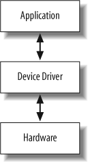
Because the device driver contains the code to operate the
hardware, the application software does not need to be complicated by
these details. For example, looking back at the Blinking LED program,
the file led.c is the LED device
driver. This file contains all of the knowledge about how to initialize
and operate the LED on the Arcom board. The LED device driver provides
an API consisting of ledInit and
ledToggle. The application in
blink.c uses this API to toggle the
LED. The application does not need to concern itself with the operation
of GPIO registers in the PXA255 in order to get the LED to perform a
certain task.
The philosophy of hiding all hardware specifics and interactions within the device driver usually consists of the five components in the following list. To make driver implementation as simple and incremental as possible, these elements should be developed in the order they are presented.
An interface to the control and status registers.
For a commonly used memory-mapped I/O, the first step in the driver development process is to create a representation of the memory-mapped registers of your device. This usually involves studying the databook for the peripheral and creating a table of the control and status registers and their offsets. The method for representing the control and status registers can be whatever style you feel comfortable implementing.
Variables to track the current state of the physical (and logical) devices.
The second step in the driver development process is to figure out what state variables you will need. For example, we’ll probably need to define variables to remind us whether the hardware has been initialized. Write-only registers are also good candidates for state variables.
Some device drivers create more than one software device for the underlying hardware. The additional instance is a purely logical device that is implemented over the top of the basic peripheral hardware. Think about a timer, for example. It is easy to imagine that more than one software timer could be created from a single hardware timer/counter unit. The timer/counter unit would be configured to generate a periodic clock tick, say, every millisecond, and the device driver would then manage a set of software timers of various lengths by maintaining state information for each.
A routine to initialize the hardware to a known state.
Once you know how you’ll track the state of the physical (and logical) device, you can begin to write the functions that actually interact with and control the hardware. It is probably best to begin with the hardware initialization routine. You’ll need that one first anyway, and it’s a good way to get familiar with device interaction.
An API for users of the device driver.
After you’ve successfully initialized the device, you can start adding other functionality to the driver. A first step in the design for the device driver is to settle on the names and purposes of the various routines, as well as their respective parameters and return values. After this step, all that’s left to do is implement and test each API function. We’ll see examples of such routines in the next section.
Interrupt service routines.
It’s best to design, implement, and test most of the device driver routines before enabling interrupts for the first time. Locating the source of interrupt-related problems can be quite challenging. If you add possible bugs present in the other driver modules to the mix, it could even become impossible. It’s far better to use polling to get the guts of the driver working. That way you’ll know how the device works (and that it is indeed working) when you start looking for the source of your interrupt problems—and there will almost certainly be problems.
A Serial Device Driver
The device driver example that we’re about to discuss is designed to control a serial port. The hardware for this device driver uses a UART (which is pronounced “you-art” and stands for Universal Asynchronous Receiver Transmitter) peripheral contained within the PXA255 processor. A UART is a component that receives and transmits asynchronous serial data. Asyncrhonous means that data can come at unexpected intervals, similar to the input from a keyboard. A UART accepts a parallel byte from the processor. This byte is serialized, and each bit is transmitted at the appropriate time. Reception works in the reverse.
The PXA255 processor has four on-chip UARTs. For this example, we will use the Full Function UART (FFUART), which is connected to the Arcom board’s COM1 port. (Note that this is the same COM port used on the Arcom board by RedBoot, eliminating the need to switch cables. The FFUART registers start at address 0x40100000.)
Before writing any software for the serial device driver, you should understand the hardware block diagram—that is, how the signals go from the peripheral to the outside world and back. This typically includes looking over the relavant portion of the schematic and gathering the datasheets for the different ICs. A block diagram for the serial port is shown in Figure 7-2.
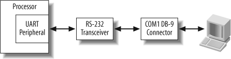
As shown in Figure 7-2, the PXA255 UART connects to the RS-232 Transceiver, which then connects to the COM1 DB-9 connector on the Arcom board. The transceiver converts the voltage level that the Arcom board’s processor uses to RS-232 voltage levels. This allows the Arcom board’s UART to communicate with a PC via its serial port.
The next step is to understand how the particular peripheral works. What ICs need to be programmed in order to control the peripheral? For this serial driver, we only need to focus on the UART peripheral registers in the processor. The information about these registers is contained in the processor’s documentation.
For information about the PXA255 processor UARTs, check the PXA255 Processor Developer’s Manual—specifically, Section 10: UARTs. Information about interrupts is contained in Section 4.2: Interrupt Controller. While reading this documentation, the goal is to get an understanding of several different concepts, including:
The register structure for controlling the peripheral—that is, how to set up communications and how to get data into and out of the peripheral
The addresses of the control and status registers
The method that will be used for the peripheral’s operation (namely, polling or interrupts)
If using interrupts, what conditions can cause interrupts, how the software driver is informed when an interrupt occurs, and how the interrupt is acknowledged
Get a firm grasp on what the device driver will need to do to get the peripheral to perform its task within the system. Once these initial steps are complete, you can move on to the task of writing the device driver software.
Register interface
The first step for the serial device driver is to define
the register interface. For this example, we use a
struct overlay for the UART registers, which are
memory-mapped. The struct overlay, uart_t, is shown here:
typedef struct
{
    uint32_t data;
    uint32_t interruptEnable;
    uint32_t interruptStatus;
    uint32_t uartConfig;
    uint32_t pinConfig;
    uint32_t uartStatus;
    uint32_t pinStatus;
} volatile uart_t;
The variable pSerialPort is
used to access the UART registers at address 0x40100000 and is
defined as:
uart_t *pSerialPort = (uart_t *)(0x40100000);
State variables
Next, we define variables to track the current state of the
hardware. A struct of serial driver parameters called
serialparams_t is defined. The
global variable gSerialParams is
used in the serial device driver to encapsulate and help organize
the configuration parameters.
The variable bInitialized
is used in the serial initialization routine to keep track of the
hardware configuration state. You may notice that in the following
code, enumerated types are defined for the parity (parity_t), data bits (databits_t), and stop bits (stopbits_t). The enumerators are set to
bitmask values in the UART configuration register. The enumerations
simplify the UART configuration programming and help make the code
more readable.
/* UART Config Register (LCR) Bit Descriptions */
#define DATABITS_LENGTH_0           (0x01)
#define DATABITS_LENGTH_1           (0x02)
#define STOP_BITS                   (0x04)
#define PARITY_ENABLE               (0x08)
#define EVEN_PARITY_ENABLE          (0x10)

typedef enum {PARITY_NONE, PARITY_ODD = PARITY_ENABLE,
              PARITY_EVEN = (PARITY_ENABLE | EVEN_PARITY_ENABLE)} parity_t;

typedef enum {DATA_5, DATA_6 = DATABITS_LENGTH_0, DATA_7 = DATABITS_LENGTH_1,
              DATA_8 = (DATABITS_LENGTH_0 | DATABITS_LENGTH_1)} databits_t;

typedef enum {STOP_1, STOP_2 = STOP_BITS} stopbits_t;

typedef struct
{
    uint32_t dataBits;
    uint32_t stopBits;
    uint32_t baudRate;
    parity_t parity;
} serialparams_t;

serialparams_t gSerialParams;
Initialization routine
The initialization routine serialInit sets up the default
communication parameters for the serial device driver. The UART
registers are programmed in the routine serialConfig, which gets passed in the
gSerialParams variable. The
variable bInitialized is used to
ensure that the serial port is configured only once.
/**********************************************************************
 *
 * Function:    serialInit
 *
 * Description: Initialize the serial port UART.
 *
 * Notes:       This function is specific to the Arcom board.
 *              Default communication parameters are set in
 *              this function.
 *
 * Returns:     None.
 *
 **********************************************************************/
void serialInit(void)
{
    static int bInitialized = FALSE;

    /* Initialize the UART only once. */
    if (bInitialized == FALSE)
    {
        /* Set the communication parameters. */
        gSerialParams.baudRate = 115200;
        gSerialParams.dataBits = DATA_8;
        gSerialParams.parity = PARITY_NONE;
        gSerialParams.stopBits = STOP_1;

        serialConfig(&gSerialParams);

        bInitialized = TRUE;
    }
}
Device driver API
Now additional functionality can be added by defining
other serial device driver API functions. A serial device driver API
should have functions to send and receive characters. For sending
characters, the function serialPutChar is used; for receiving
characters, serialGetChar is
used.
The serial device driver API function serialPutChar waits until the transmitter
is ready and then sends a single character via the serial port.
Transmitting is done by writing to the UART data register. The
following code shows the serialPutChar function.
#define TRANSMITTER_EMPTY           (0x40)

/**********************************************************************
 *
 * Function:    serialPutChar
 *
 * Description: Send a character via the serial port.
 *
 * Notes:       This function is specific to the Arcom board.
 *
 * Returns:     None.
 *
 **********************************************************************/
void serialPutChar(char outputChar)
{
    /* Wait until the transmitter is ready for the next character. */
    while ((pSerialPort->uartStatus & TRANSMITTER_EMPTY) == 0)
        ;

    /* Send the character via the serial port. */
    pSerialPort->data = outputChar;
}
The serial device driver API function serialGetChar waits until a character is
received and then reads the character from the serial port. To
determine whether a character has been received, the data ready bit
is checked in the UART status register. The character received is
returned to the calling function. Here is the serialGetChar function:
#define DATA_READY                  (0x01)

/**********************************************************************
 *
 * Function:    serialGetChar
 *
 * Description: Get a character from the serial port.
 *
 * Notes:       This function is specific to the Arcom board.
 *
 * Returns:     The character received from the serial port.
 *
 **********************************************************************/
char serialGetChar(void)
{
    /* Wait for the next character to arrive. */
    while ((pSerialPort->uartStatus & DATA_READY) == 0)
        ;

    return pSerialPort->data;
}
Because this serial device driver does not use interrupts, the final step in the device driver philosophy—implementing device driver interrupt service routines—is skipped.
Testing the Serial Device Driver
Now that the serial device driver is implemented, we need to verify that it operates correctly. It is important to check the individual functions of your new API before integrating the driver into the system software.
To test the serial device driver, the Arcom board’s COM1 port must be connected to a PC’s serial port. After making that connection, start a terminal program, such as HyperTerminal or minicom, on the PC. (The serial port parameters should not need to be changed, because the default serial device driver parameters are the same ones used by RedBoot.)
The main function
demonstrates how to exercise the serial device driver’s functionality.
You might notice that this software has the beginnings of a
command-line interface—an indispensable tool commonly implemented in
embedded systems.
First, the serial device driver is initialized by calling
serialInit. Then several characters
are output on the PC’s serial port to test the serialPutChar function. If the serial device
driver is operating properly, you should see the message start output on your PC’s terminal
screen.
Next, a while loop is entered
that checks whether a character has been received by calling serialGetChar. If a character comes into the
serial port, it is echoed back. If the user enters q in the PC’s terminal program, the program
exits; otherwise, the loop continues and checks for another incoming
character.
#include "serial.h"

/**********************************************************************
 *
 * Function:    main
 *
 * Description: Exercise the serial device driver.
 *
 * Notes:
 *
 * Returns:     This routine contains an infinite loop, which can
 *              be exited by entering q.
 *
 **********************************************************************/
int main(void)
{
    char rcvChar = 0;

    /* Configure the UART for the serial driver. */
    serialInit();

    serialPutChar('s'),
    serialPutChar('t'),
    serialPutChar('a'),
    serialPutChar('r'),
    serialPutChar('t'),
    serialPutChar('\r'),
    serialPutChar('\n'),

    while (rcvChar != 'q')
    {
        /* Wait for an incoming character. */
        rcvChar = serialGetChar();

        /* Echo the character back along with a carriage return and line feed. */
        serialPutChar(rcvChar);
        serialPutChar('\r'),
        serialPutChar('\n'),
    }

    return 0;
}
Extending the Functionality of the Serial Device Driver
Although the serial driver is very basic, it does have core functionality that you can build upon to develop a more robust (and more useful) program. This device driver provides a platform for learning about the operation of UARTs. Following is a list of possible extensions you can use to expand the functionality of this driver. Keep these in mind for other drivers you develop as well.
- Selectable configuration
You can change
serialInitto take a parameter that allows the calling function to specify the initial communication parameters, such as baud rate, for the serial port.- Error checking
It is important for the device driver to do adequate error checking. Another enhancement would be to define error codes (such as parameter error, hardware error, etc.) for the device driver API. The functions in the device driver would then use these error codes to return status from the attempted operation. This allows the higher-level software to take note of failures and/or retry.
- Additional APIs
Adding
serialGetStrandserialPutStr(which would require buffering of the receive and transmit data) might be useful. The implementation of the string functions could make use of theserialGetCharandserialPutCharfunctions, if it were reasonably efficient to do so.- FIFO usage
Typically, UARTs contain FIFOs for the data received and transmitted. Using these FIFOs adds buffering to both the receive and transmit channels, making the UART driver more robust.
- Interrupts
Implementing UART interrupts for reception and transmission is usually better than using polling. For example, in the function
serialGetChar, using interrupts would eliminate the need for the driver to sit in a loop waiting for an incoming character. The application software is thus able to perform other work while waiting for data to be received.
Device Driver Design
Most embedded systems have more than one device driver. In fact, sometimes there might be dozens. As your experience grows, you will need to understand the way different devices in the system interact with each other. You will also have to consider how the application software will use the device driver so that you can provide an adequate API.
You will need to have a good understanding of the overall software design and be aware of possible issues in the system. Getting input from multiple sources can lead to a better design. Here are some areas to consider when designing a software architecture that includes various device drivers:
- Interrupt priorities
If interrupts are used for the device drivers in a system, you need to determine and set appropriate priority levels.
- Complete requirements
You need to be aware of the requirements of the various peripherals in the system. You don’t want to design and implement your software in a manner that unknowingly handicaps the peripheral from operating as it is intended. This can cause such major problems that the product might not be usable until the system functions as specified. It’s a good idea to use software design reviews to flush out any potential problems that might have been overlooked by an individual developer.
- Resource usage
It is important to understand what resources are necessary for each device driver. For example, imagine designing an Ethernet device driver in a system with a very limited amount of memory. This limitation would affect the buffering scheme implemented in the Ethernet driver. The driver might accommodate the storage of only a few incoming packets, which would affect the throughput of the Ethernet interface.
- Resource sharing
Beware of possible situations where multiple device drivers need to access common hardware (such as I/O pins) or common memory. This can make it difficult to track down bugs if the sharing scheme is not thoroughly thought out ahead of time. We will take a look at mechanisms for resource sharing in Chapters 8 and 10.