
In the previous chapters, we discussed some of the core concepts of the Entity Framework, the Entity Data Model (EDM), querying, and other straightforward operations. The simple database and console application we used illustrated key points and kept you focused on the lessons. Now it’s time to look at some more realistic scenarios.
In this chapter, we’ll create and work with a more realistic model. The model will be contained in its own assembly so that you can reuse it in other applications in your enterprise.
The chapter will also address the important task of clarifying the names used in a model that has been created from a database. You will also learn about many-to-many relationships as well as a few more tips about mapping stored procedures.
The example company for which we will be writing software is called BreakAway Geek Adventures. This small company arranges adventure vacations for hard-working programmers who need a break. Examples of vacations that can be booked through BreakAway Geek Adventures include whitewater rafting in Belize and bicycling in Ireland. The company has been in business for a number of years and has an old application that uses a SQL Server database for its data store. Now it’s time to write shiny new applications for this venerable firm in .NET, leveraging the Entity Framework.
Note
You can download a script for creating this database from the book’s website. Look for the database named BreakAway. There is a version for SQL Server 2005 and a version for SQL Server 2008.
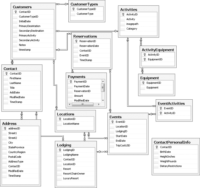
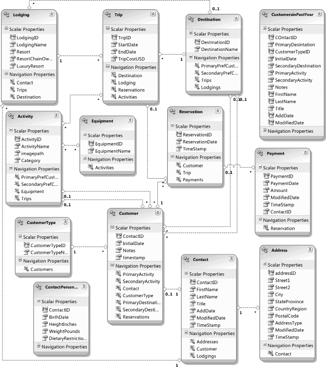
Figure 7-1 shows the BreakAway database schema.
The first step is to create the new model. Rather than create the EDM directly in the Windows application, in this chapter you will create a separate project for the EDM. This is a good start on your way to planning for larger applications.
In Visual Studio, create a new Class Library project named BreakAwayModel.
Delete the Class1 file that was automatically created.
Add a new ADO.NET EDM to the project. Change the default name (Model1.edmx) to BAModel.edmx.
On the Choose Model Contents page, choose Generate from Database and then select the BreakAway Data Connection if it has already been added to Visual Studio. If it hasn’t been added, create it on the fly using the New Connection button. Leave the default connection settings name, BreakAway, alone for now and go to the next page of the wizard.
On the Choose Your Database Objects page, check all three objects: Tables, Views, and Stored Procedures.
Open the Tables node. You will see that because the database contains a diagram, the table that controls the diagram is listed (
sysdiagrams). Uncheck that since you don’t need the diagram in your model. Creating the diagram in SQL Server Management Studio also resulted in seven stored procedures and one function being added for the sake of diagramming. Their names begin with either fn_ or sp_ and contain the word diagram. They won’t interfere with your model, but you can uncheck these procedures and functions if you prefer.Leave the default model namespace intact. You’ll get a chance to change that shortly.
Wrap up model creation by clicking the Finish button.
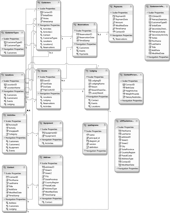
The newly created model will open in the Designer window and should look something like Figure 7-2.
The first thing you should always do with a newly generated model
is make sure the Entity names and
EntitySet names make sense. The
Entity names should be singular
(Contact, Address, Customer, etc.) and the EntitySet names should be the plural form of
the Entity names (Contacts, Addresses, Customers, etc.). The word
equipment poses a challenge since the singular and
plural versions are the same. The rule that the Designer follows when
you create new entities in the Designer is to append the word
Set to the name of the new entity, so we’ll follow
that convention and use EquipmentSet in this model. Although you
can edit the Entity names right in
the Designer, you can edit the EntitySet names only in the Properties window.
You may find it more efficient to edit both in the Properties
window.
Note
There are three ways to get an entity’s properties to display in the Properties window:
Select the entity in the Designer.
Select the entity in the Model Browser.
Select the entity from the drop-down list of objects in the Properties window.
The database has a table named Events that refers to the trips that
BreakAway schedules. The original name of this table was an
unfortunate choice because the .NET word Event is
a reserved keyword in both VB and C#. This normally isn’t a problem,
but if you were to use Event as the entity name,
the EntityObject named Event would create a conflict. With the EDM,
you can rename the entity without having to rename the database table.
The term Trip also makes more sense, so renaming
this will be a bonus. As you fix the names of the Entity objects and EntitySets, rename the Events entity to Trip. The entity will still map back to the
Events table, so everything will
stay in sync.
You should also change the EventID property name to TripID so that as you are working with
objects, you won’t have the confusion of an entity whose ID property
doesn’t match the name of the entity.
Do the same for the entity named Locations, changing it to Destination. You’ll need to change the
ID and Name properties as well, to DestinationID and DestinationName.
The Designer will pop up an error message when you try to change
the names of two entities. The first is CustomerTypes and the second is Activities. The problem is that the entities
contain properties with the same names you would like the entities to
have.
Before you can change the CustomerTypes entity name to CustomerType, you will need to rename its
CustomerType property. Change the
name to CustomerTypeName. Then
change the Activity property of the
Activities entity to ActivityName. You can make these changes in
the Designer or in the Properties window.
You may also notice that the Equipment entity has a property called
Equipment1. That is because the
wizard saw that the property name matched the entity name and
therefore appended a “1” to the property. Change that property to
EquipmentName.
Now you will be able to change the names of the entities without problems.
Table 7-1 shows the names that result. If you make these same changes, the queries and other code that follow will work properly.
Table 7-1. Entity and EntitySet name changes
Entity | EntitySet |
|---|---|
Activity *Change the Activity property to ActivityName | Activities |
Address | Addresses |
Contact | Contacts |
Customer | Customers |
CustomerType *Change the CustomerType property to CustomerTypeName | CustomerTypes |
Equipment *Change the Equipment1 property to EquipmentName | EquipmentSet |
Trip (was Events) | Trips (was Events) |
Destination (was Locations) | Destinations |
Lodging | Lodgings |
Payment | Payments |
Reservation | Reservations |
vOfficeAddress | vOfficeAddresses |
Warning
You’ll notice some bad behavior by the Designer as you rename
some of the entities. When you’re renaming the EntitySets, all is well, but when you
rename the entity, the Designer will automatically rename the
EntitySet using its pattern for
new entities, which is to append the word Set
onto the end.
This means that after changing the entity names, you’ll need
to reedit the EntitySet names.
Thankfully in this model, this will occur with only eight
entities.
There is still a bit of cleaning up to do. Next, you will fix the names of the navigation properties so that they make sense when you are building queries and working with the objects returned from those queries.
Navigation property names should be plural when pointing to a collection (e.g., reservations that a customer has made) and singular when pointing to a reference (the customer who made a reservation).
The Customer entity has some
odd navigation properties: Locations
and Locations1, and Activities and Activities1. The Activity and Location entities each have Customers and Customers1 in the Activity entity and the Destination entity. Fix the other navigation
properties as shown in Table 7-2, and then we’ll
come back to these.
Table 7-2. Changes made to navigation names to better represent their multiplicity
Entity | Original navigation property name | Fixed navigation property name | Reason |
|---|---|---|---|
Contact | Address | Addresses | 1:* Navigation |
Customers | Customer | 1:1 Navigation | |
Lodging | Lodgings | 1:* Navigation | |
Customer | CustomerTypes | CustomerType | *:1 Navigation |
Trip | Locations | Destination | *:1 Navigation and entity name changed |
Activity | Events | Trips | Entity name changed |
Destination | Lodging | Lodgings | 1:* Navigation |
Events | Trips | Entity name changed | |
Lodging | Destinations | Destination | *:1 Navigation and entity name changed |
Events | Trips | Entity name changed | |
Payment | Reservations | Reservation | *:1 Navigation |
Reservation | Customers | Customer | *:1 Navigation |
Events | Trip | *:1 Navigation and entity name changed |
As you write queries against this model going forward, the queries
will be more logical. Rather than coding against Reservation.Customers, when there will always
be just one customer, you will be able to use Reservation.Customer.
Now we can go back to work on the Customer entity. It has those two funny
pairs of navigation properties: Activities and Activities1, and Locations and Locations1. These property pairs will make
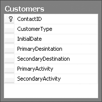
more sense if you check the Customers table in the database, shown in Figure 7-3. BreakAway keeps
track of each customer’s first and second preferences for destination
and activity. This is not an uncommon database scenario, but the
wizard will always create the names in this way, so let’s see how to
add clarity to these names.
The navigation property names are derived simply from the name of the table on the other end of the relationship. Since there are two associations to one entity, the wizard appended a “1” to the second navigation property.
Note
Did you notice that the PrimaryDestination column was misspelled
in the database? In the previous application, the developer had to
constantly tangle with this field name. But with the EDM it will no
longer be a problem. Though a small detail, this is a really nice
benefit of using the data model. Changing the field name in the
database could have a big impact in the database schema, especially
if that field name is used in views, functions, or stored
procedures. In the model, you can change the property to whatever
name you like without impacting the database.
Before you can rename these navigation properties, you’ll need
to figure out which foreign key fields the navigation properties
belong to. For example, does Customer.Activities refer to the
PrimaryActivity or the SecondaryActivity?
You can do this by looking at the properties of each navigation property and seeing which association it is bound to, and then looking at that association and seeing which field is involved.
Let’s start with Activities.
Click the Activities navigation
property in the Customer entity. In
its Properties window, BreakAway.FK_Customers_Activities is the
Association
property.
Use the Properties window drop-down (near the top of the Properties window) to select that association.
Note
There are a number of ways to select an association in the model. The Properties window drop-down is one way to select the association. You can also select it in the Model Browser. An additional method is to right-click a navigation property and to choose Select Association from its context menu. Any of these methods will cause the association to be highlighted in the Designer and its properties to display in the Properties window.
Right-click the association’s line in the model and select Table
Mapping from the context menu. The term Table
Mapping seems to be used generically in the Designer, even
when the mapping is an Association Mapping. In Figure 7-4, you can see
that this association is for the PrimaryActivity.
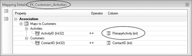
Figure 7-4. Checking the mapping details of an association to discover which foreign key is involved in the association
Rename the Activities
navigation property to PrimaryActivity and the Activities1 navigation property to SecondaryActivity.
You can do the same detective work for the
Locations and Locations1 navigation properties to see
which one should be named PrimaryDestination and which one should be
named SecondaryDestination.
You need to fix the other ends of these associations as well.
The Activity entity has two
navigations back to the Customer
entity. Going in this direction, the navigations represent “Customers
who have listed this activity as their primary activity” and
“Customers who have listed this activity as their secondary activity.”
Rename Customers to PrimaryPrefCustomers and Customers1 to SecondaryPrefCustomers. Make the same
changes to the Customers and
Customers1 navigation properties in
the Destination entity.
The database has a number of stored procedures. For now, we’ll do
function mapping for the procedures for the Payments table—InsertPayment, UpdatePayment, and DeletePayment—using the same technique
you learned in Chapter 6.
Open the Stored Procedure Mappings window for the Payment entity and select the appropriate
functions for insert, update, and delete.
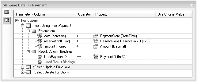
The InsertPayment function
returns a newly generated PaymentID
called NewPaymentID. The parameter
names don’t match the property names of the entity; therefore, you
will need to manually map some of the properties.
Notice that the InsertPayment
function needs to know the ReservationID. In the model, Reservation is a navigation property of the
Payment entity. You will have
access to the navigation property in the mapping window, so you can
select Reservation.ReservationID to map to the
required parameter.
Be sure to map that to the Result Column Bindings item, as you
did for the InsertContact function in the preceding
chapter. The insert mapping should look the same as in Figure 7-5.
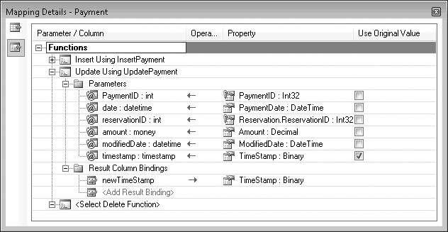
When you are mapping the UpdatePayment function, you will also have
to manually map the properties whose names don’t match the input
parameters.
Because of the way this stored procedure works, you can take
advantage of the special Use Original Value column that exists only
for the update functions. The stored procedure performs a
concurrency check against the timestamp field. If anyone edited the
record in between the time the user retrieved the record and when he
attempted to save changes, the order won’t be updated and an
OptimisticConcurrencyException
will be thrown. You’ll learn more about working with concurrency in
Chapter 18.
When a payment is updated, the database will automatically
update the timestamp field. The UpdatePayment procedure returns the new
timestamp value. Map that return value as shown in Figure 7-6.
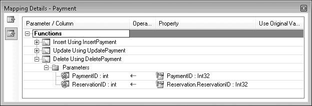
A typical stored procedure for deleting a record takes the
primary key field as a parameter. When you map the Delete function you will see that the
DeletePayment function has not
only the PaymentID as a
parameter, but also ReservationID.
This is in the database in advance to simplify your task of mapping the functions, but you will not typically have the additional parameter. Why is it there and why should it make the mapping simpler? A mapping requirement with the Entity Framework makes it necessary.
In the Insert and Update stored procedures, it makes sense
to have the ReservationID as a
parameter because that supplies the ForeignKey value that the Payment record in the database
needs.
As a general rule, the Entity Framework requires properties
that are involved in association mappings to be mapped in all of the
function mappings for the entity. Because Payment has an association to Reservation—even in the function where it
seems illogical, Delete—you must
map the property that the association revolves around (Reservation.ReservationID). This is
not meant to aggravate you or your database administrator, but it is
how the Entity Framework is able to generically deal with all of the
things you might try to achieve in your models and your queries. So,
unfortunately, developers are stuck with the rule regardless of
whether it makes sense to them. Putting the extra parameter(s) into
the stored procedure in the database is the easiest way to deal with
this.
If that’s not an option in your application, the alternative is to modify your model’s Store Schema Definition Layer (SSDL). You will learn in Chapter 13 that it’s possible to modify the SSDL to create virtual tables, stored procedures, and functions that don’t physically exist in the database. The downside to modifying the SSDL manually is that if you update the model, many of the SSDL modifications will be overwritten.
At this stage in the book, it is simpler to just have the
parameter written directly into the stored procedure. Map the
DeletePayment function so that it
matches Figure 7-7.
You now have an Entity Data Model from a highly normalized database. Since you have already done so much work on this model, we will leave the task of performing more advanced customizations to Chapters 12 and 13. Figure 7-8 shows the current view of the model, with some of the entities moved around to make it more visually appealing.
There is one more thing to point out about this model: the two
many-to-many relationships. BreakAway Adventures’ database keeps track
of which type of equipment is needed for which activities. It also
tracks which activities will be available on which events (“trips” in
the model). To accomplish this, an ActivityEquipment join table between Equipment and Activities defines many-to-many relationships
between equipment and activities, and an EventActivities join table between Activities and Events defines many-to-many relationships
between activities and events, as shown in Figure 7-9.
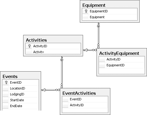
These tables did not appear in the model as entities. The EDM has
the ability to represent many-to-many relationships while hiding the
join in the mappings. But it can do this only when the join table has
just the relevant keys and no extraneous fields. These two tables meet
that criterion, as they have only the IDs of the items they are joining.
If the join tables had additional properties, such as DateCreated, the EDM would have created
entities for them.
Instead, the joins are controlled in mappings; in the conceptual
layer the relationships are expressed as navigation properties. Example 7-1 shows the mapping for the
EventActivities
association in the XML file. The mapping identifies the EventActivities table as
the target of the mapping, and then shows its ActivityID field wired up to the ActivityID field of the EventActivities table. Meanwhile, its EventID field is wired up to the EventID field of the Events table.
Example 7-1. Many-to-many association mapping
<AssociationSetMapping Name="EventActivities"
                       TypeName="BreakAway.EventActivities"
                       StoreEntitySet="EventActivities">
  <EndProperty Name="Activities">
    <ScalarProperty Name="ActivityID" ColumnName="ActivityID" />
  </EndProperty>
  <EndProperty Name="Events">
    <ScalarProperty Name="EventID" ColumnName="EventID" />
  </EndProperty>
</AssociationSetMapping>
As you can see in Figure 7-10, Activity and Equipment are joined in a many-to-many
relationship. Thanks to the original table names, the navigation
property names happen to be just right and don’t need editing. Each
piece of equipment has activities and each activity has a collection of
equipment.
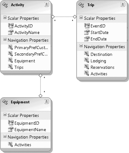
Each activity also has trips and every trip has a collection of activities. It will be very convenient not to have to construct joins when traversing these relationships in queries. Because the join tables contain only the keys involved, the EDM can easily represent the relationship without the aid of a join entity.
This mapping not only enables a convenient association directly between the two entities, but also manages querying, inserts, and updates across this join. You’ll see this in action as you move throughout the book.
Now it’s time to build the model into an assembly that you will be able to use in the many projects that you will be building in upcoming chapters.
Before you compile the model, you will want to change a few names so that when you access the model and its classes from another project, you won’t have to work with cumbersome names.
You will have to make references to the assembly namespace throughout the code of your other applications that are using that namespace. Therefore, it will be handy to have a nice, short name for the namespace. The acronym for BreakAway Geek Adventures is BAGA, which is a good option.
Open the project’s Properties window, and on the first page, Application, change the root namespace (VB)/default namespace (C#) to BAGA.
When you created the model with the Entity Data Model Wizard,
you left the default name for the EntityContainer as BreakAway. Change that name to BAEntities. Remember that the place to do
this is in the model’s Properties window, which you can access when
the model is open in the Designer.
Note
When you change this name and save the model, the ConnectionString name in the app.config file should change to
BAEntities as well. It’s not a
bad idea to double-check that this happened by looking in the
app.config file.
Changing this name will make typing Entity SQL expressions easier, as you will have to include this container name in every Entity SQL expression.
When a project containing an EDMX is compiled, the compiler
extracts the StorageModels, ConceptualModels, and Mappings sections of the EDMX file and
creates individual schema files from them. In this case, the files are
BAModel.ssdl, BAModel.csdl, and
BAModel.msl. By default, these
files are embedded into the assembly that is built from the
project.
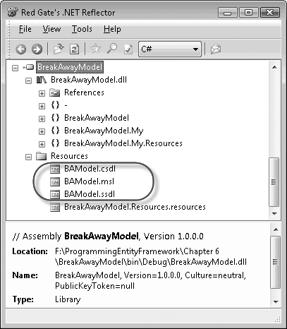
Figure 7-11 shows the compiled assembly in Red Gate’s Reflector tool, with the embedded files listed under Resources.
If you look at the metadata portion of the EntityConnection string that the Entity Data
Model Wizard inserted into the app.config file, you’ll see the following
notation:
res://*/BAModel.csdl|res://*/BAModel.ssdl|res://*/BAModel.msl
Much of the functionality in the Entity Framework depends on its
ability to read the schema files. The * in the metadata of the connection string
indicates that you can find the files in the assembly.
Having the model in the assembly is convenient when you don’t expect the model to change often after it has been deployed. However, you may want to take advantage of the model’s loose coupling at some point. For example, you or your database administrator might modify the database in a way that changes the schema, but introduces nothing new that would impact the objects in the application. In this case, you would need to update the model so that the database changes are reflected in the SSDL schema. Then, because of this change, you would need to adjust some of the mappings to be sure that the entities are mapped correctly to the SSDL. So, in this scenario, the SSDL and MSL layers change, but no change is made to the conceptual layer.
You may not want to have to rebuild and redeploy the assembly. Doing so may also affect the versioning of your application.
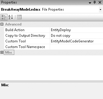
Although the files are embedded by default, there is an option to have the files exist outside the assembly. The model has a property called Metadata Artifact Processing. The property is available in the model’s Properties window, as shown in Figure 7-12.
Notice that the connection string has changed. The metadata no
longer has a * to indicate that
the files are embedded. Instead, it shows the relative path of the
files. You will find them in the project’s output directory, which
by default is in either the bindebug or the
bin
elease folder in the project
folder.
You can put the schema files anywhere you want. However, you
will need to be sure that the connection string points to the
correct path. If, for example, you place the files in
C:EDMS, you’ll need to modify the metadata attribute to the
following:
metadata=C:EDMSBAModel.csdl| C:EDMSBAModel.ssdl| C:EDMSBAModel.msl
Note
Although this chapter covered creating a model in a separate
assembly, it’s useful to be aware of a special case for the
metadata attribute. If you
create an EDM inside an ASP.NET Web Site Project, because of the
way in which Web Site Projects are compiled, the path will be
affected. The entire metadata attribute will be metadata=res://*. This does not happen
with Web Application Projects.
You can learn more about the EntityConnection’s metadata attribute in the MSDN Library
documentation.
In this chapter, you went through the steps of creating an EDM from a more realistic database, which you will be using throughout the rest of this book. Then you spent some time cleaning up many of the automatically created entity and property names so that they will be more logical when it comes time to use the model in your applications.
You have now prepared an assembly that can easily be referenced from a variety of projects and used in other applications. Because the runtime schema files are embedded into the assembly, it will be even simpler to reuse and share the model.
In the next chapter, you will write your first Windows applications using this model.