In the last chapter, we covered the basics of microcontrollers and how to set up a development environment. To really use microcontrollers, however, we need to interface them to the outside world. This will require a basic understanding of electronics. While it would be impossible to fully cover this vast and complicated field in a single chapter, let alone an entire book, this chapter provides an introduction to the principles of electronics and an overview of some of the components you’ll be using with your microcontroller.
Electronics can be split into two main areas: analog electronics and digital electronics. Analog electronics deals with electronics in which the components within the circuit can have several states; thus, we say that analog electronics deals with continuous circuits. Digital circuits on the other hand have two states, and thus digital electronics deals with discrete circuits. In this chapter, I will discuss both.
Electricity is all about the flow of electrons. To understand electrons, let’s talk about the atom a bit. The atom is said to be the smallest part of matter that can exist, and this is all good except it does not stop there. Even within the atom, there exists a myriad of subatomic particles that are described as a zoo of particles. We have protons, neutrons, electrons, quarks, mesons, and the list can go on and on.
Subatomic physics could take a lifetime to study. We will skip the complexities of that and describe the atom as being composed of three main particles. These are the proton, the neutron, and the electron. The proton is said to be positively charged, the neutron has no charge, and the electron has a negative charge.
Now that we have these particles in our head, one would think that they are all the same size. However, this is not so. Protons and neutrons are much larger than electrons. Something else to remember about these particles is that they are not randomly distributed in the atom. The neutrons and protons are clumped together in the center of the atom, and the electrons surround it.
This flow of electrons is called a current . These electrons flow for one simple reason; the conductors themselves are made of atoms. When we apply a voltage, which is a potential difference across two points of the conductor, it causes these electrons to flow as what is known as a current. Now, remember that the atoms of the conductor already have electrons; hence, when you cause more electrons to flow through the conductor, it causes an individual atom to essentially “toss out” electrons to their neighbor, and this process continues many, many times over at the speed of light.
So, let us recap for those of you who are still confused. Atoms are made up of things called protons, neutrons, and electrons. These electrons can flow through materials called conductors that allow them to flow and cannot flow through insulators which do not allow them to flow. When these electrons flow, they produce a current, and they flow because a potential difference also known as a voltage exists across the conductor. A substance that allows a current to flow through it is called a conductor , while a substance that does not is called an insulator . In order to flow, the current needs a closed path or loop, called a circuit .
A device called a power source has a potential difference across its terminals that can allow an electrical current to flow. In a paragraph above we talked about voltage which is the potential difference that causes a current to flow through objects. This potential difference does not come from itself however; it comes from a device that generates the electricity we need to power electronics. Cells and batteries are two such sources of electricity.
Anyone born within this era is sure to have encountered a battery in one form or another. Did you ever think about what a battery is? I mean you know there is one in your phone and in gadgets you have laying around. However, did you give any thought into what a battery is?
A battery is a device that we use to generate electricity and is made up of a collection of cells. Though we call everything that provides electrical power batteries, this is not the case. A cell is the single unit that produces power. A battery is formed when we have a collection of cells.
A primary cell is a cell in which the chemical reaction that took place to generate the electricity is not easily reversed. How many times have you replaced cells from clocks and remote controls around your home? Once a primary cell is depleted, it is meant to be discarded.
The alkaline cells you use to power your toys and gadgets are typically primary cells. When that AA or AAA cell dies, you toss it away and put in a new one, as is the intended use.
If we look at the cell, we will see two markings. The positive end of your power source is called the anode, and you see it marked with a little cross symbol (+). The negative end of your power source is called the cathode, and you see it marked with a little dash symbol (-). This cathode is sometimes called the ground connection.
While primary cells have their uses, our shift toward “going green” as well as advances in battery technology has led us toward using cells that can be recharged after the energy within them has been depleted. We call these cells secondary cells.
A secondary cell is a cell in which the chemical reaction that produced the electricity can be reversed. Think about it; if the chemical reaction produced electricity, should not adding electricity be able to reverse the chemical reaction that generated the electricity?
This is the premise the secondary cell operates under. Thanks to its battery chemistry, it can be recharged. These types of cells are common in our modern electronic gadgets such as our phones and tablet computers.
The electronic components we’ll use throughout this book have different physical properties that allow electrons to flow through them in a certain way. When we work with these components, all we’re doing is taking advantage of these properties to produce certain desirable effects. In this chapter, I’ll discuss each component in turn to show how it can influence the flow of electricity.
Electrical Wires

Solid Core Wire
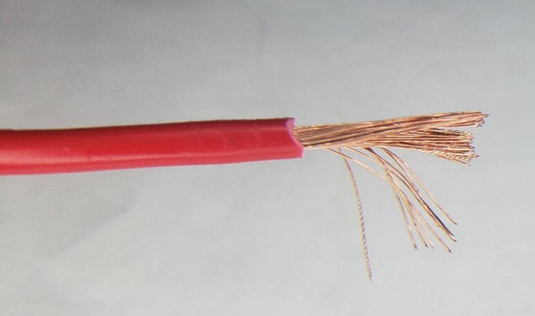
Stranded Core Wire
Stranded wires and solid core wires both have their applications. Solid core wire is very robust when it comes to resisting corrosions, and for applications where corrosion might occur, they are the preferred wire type. Stranded wire on the other hand is more flexible and is thus used in applications where there might be a lot of flexing of the wire. Solid core wire is more prone to breaking under a lot of flexing and is not good for such applications.
As you gain more experience, you will be able to determine which wire is suitable for which application. Sometimes, other factors such as cost or current handling capability may determine which type of wire you will use for your application.
Another important thing to know about wires is related to their size. The name we use to refer to the size of the wire is the gauge of the wire. The American Wire Gauge (AWG) is the standard most people use when they are dealing with wire sizes.
Something that always confuses beginners is related to the size of the wire and the number assigned to their gauge. In the AWG system, the larger the number is, the thinner the wire is. What this means is that a gauge 12 wire (common size for household wiring) is thicker than gauge 22 wire commonly found in electronics work.
Thicker wire generally means greater handling capability. When it comes to a comparison of wires, at DC voltages, a single core wire generally offers a higher current rating than a corresponding stranded wire with the same cross-sectional area. The reason is simple: it all boils down to heat.
The ability of a wire to handle current depends on how well it can remove the heat that is generated when a current is flowing through it. A single core wire simply must dissipate heat from the wire to the outside which is better than stranded wire. Think about the strand in the center of the stranded wire. The heat must go from this central strand and depend on other strands to conduct heat to the outside of the wire which leads to poorer heat dissipation.
The Breadboard
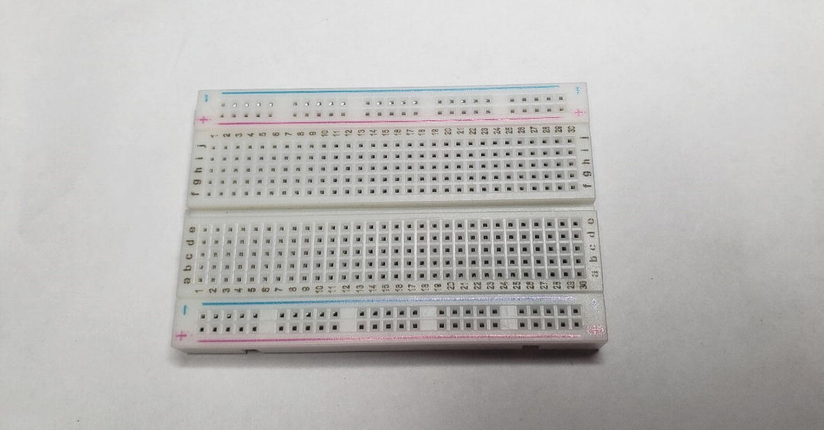
A Breadboard
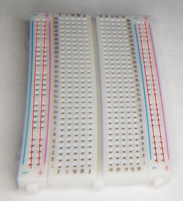
The Breadboard’s Power Rails Are Highlighted with Red Lines
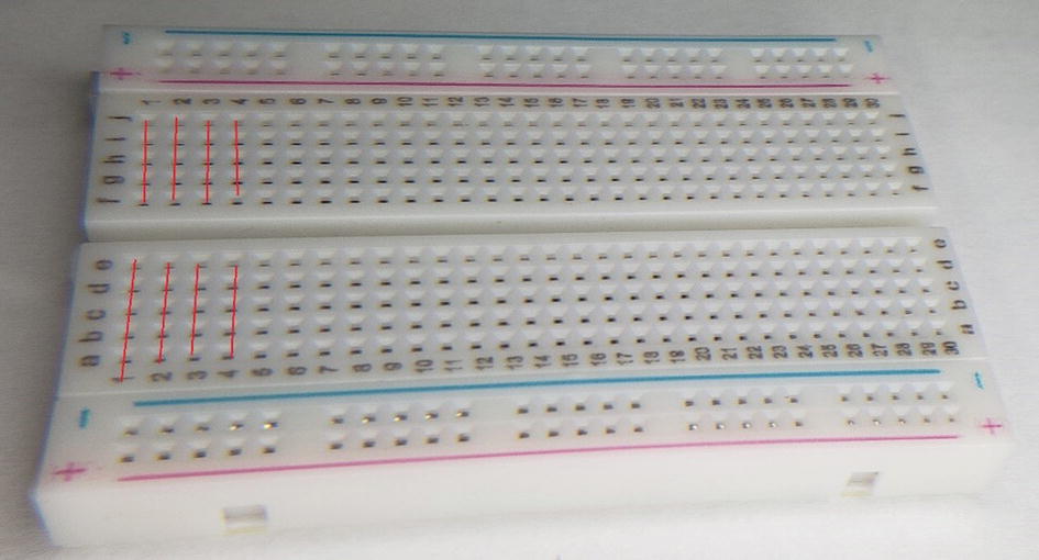
The Prototyping Area, with the First Few Rows of Sockets Highlighted in Red
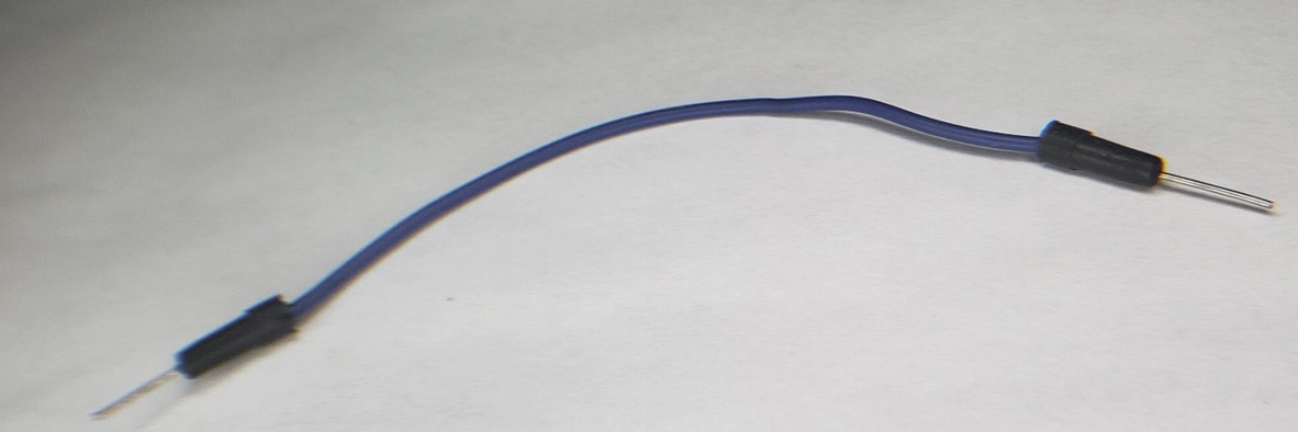
Jumper Wire
These jumper wires are used to connect different sockets together, providing a path for a current to flow through the components on the breadboard.
Electronic Schematics
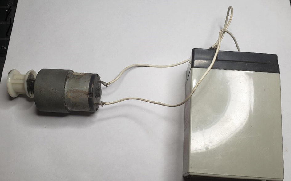
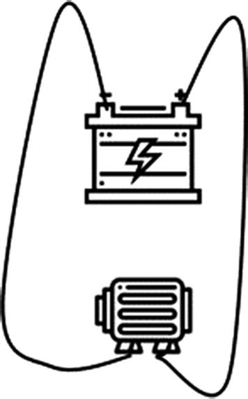
A Simple Circuit Featuring a Motor Connected to a Battery
Pictorial Representation of Our Circuit

The Same Circuit Shown Using Schematic Symbols
These terms are not set in stone however, as some people refer to circuit diagrams as schematic diagrams in some instances. However, you should be aware that a difference in how we represent our circuits exists. In this book, I use schematic diagrams as they are clearer and more concise than circuit diagrams. Also, once you understand schematic diagrams, you should be able to understand circuit diagrams without any problem.
Every component we use in electronics has its own standardized schematic symbol used to represent it. Here are the symbols for the components we have used thus far.

Wire Schematic Symbol
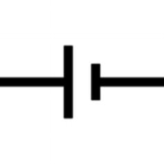
Cell Schematic Symbol
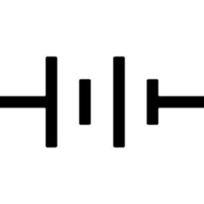
Battery Schematic Symbol

Motor Schematic Symbol
There are many more schematic symbols that will be gradually introduced as we move along.
Passive Components
We are now ready to cover what are known as passive components. They are called passive because they do not require any external source of power in order to operate. These are devices that are capable of dissipating, storing, and releasing electrical power. Passive components include resistors, capacitors, and inductors.
Resistors
A resistor is a device that resists the flow of electrons through it. This is needed to limit the current that flows into certain circuit components. If we put too much current into some components, they will be damaged, and for that reason, we use resistors to prevent this from happening. Resistors also form part of a particularly important circuit known as a voltage divider. A voltage divider turns a larger voltage into a smaller one which is useful when building certain circuits, as we will see later in this book.
We measure the amount of resistance in a substance with a unit known as ohms. When we really think about it, all resistance is is a relationship between voltage and current in a circuit. Essentially, it is a ratio of voltage across a substance to the current through it. This relationship forms something known as Ohm’s law.
Voltage = Current * Resistance
This relationship is simple but powerful! To illustrate this, let us say we have a voltage of 5 volts flowing in your circuit and a resistor with a value of 1k.
Current = Voltage / Resistance
So, we can calculate the current in the circuit to be 5v / 1000 ohm = 0.5 milliamps.
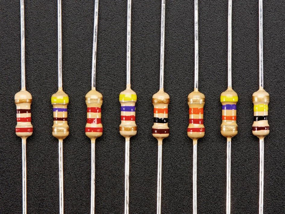
Some ResistorsCredit: Adafruit, adafruit.com
Resistor Color Codes
Color | Number |
|---|---|
Black | 0 |
Brown | 1 |
Red | 2 |
Orange | 3 |
Yellow | 4 |
Green | 5 |
Blue | 6 |
Violet | 7 |
Gray | 8 |
White | 9 |
The tolerance band may be brown to indicate a 1% tolerance, gold to indicate a 5% tolerance, silver to indicate a 10% tolerance, or no stripe at all may indicate a 20% tolerance. There are other bands that indicate other tolerance levels, but these are the ones you will most frequently encounter.
Resistors are a very well-behaved component. Rarely do you have a problem with a circuit in which resistors are the culprit. If resistors fail within a circuit, it’s either because of a poor design choice or the failure of another component that takes the resistor down with it.

The Resistor Schematic Symbol
Capacitors
Capacitors are responsible for storing electrical energy within a circuit. One of the most common uses for them is in filter circuits together with resistors. Filters in electronics are used to allow certain frequencies of electrical signals to pass through them while attenuating or reducing others. Some types of filters are even able to amplify or modify signals of the frequencies they allow to pass.
Filter circuits have many important applications; one such application is in audio signals when you want to create a two-way crossover circuit and direct all the high frequencies to a tweeter while attenuating low frequency signals.
The characteristics of capacitors are dependent on the material of which they are made; we call the material they are made from the dielectric. The dielectric will determine whether the capacitor is polarized or non-polarized. A polarized capacitor must be connected a certain way within a circuit; otherwise, it will be damaged and presents a fire hazard. Non-polarized capacitors can be connected either way in a circuit without problems.
The amount of charge a capacitor can hold, called its capacitance, is measured in a unit known as the farad. One farad is a large amount of storage, and for that reason, we usually use capacitors in small amounts, usually microfarads (μF) and picofarads (pF) – one-millionth and one-trillionth of a farad, respectively.
Some things to look out for when working with capacitors are their temperature range and their working voltage. These values are often printed on the body of the device. The temperature range represents the minimum and maximum temperatures at which the capacitor will function correctly, while the working voltage is the maximum voltage that can be fed into the capacitor. It is important not to exceed the working voltage, as it will cause damage to the device. When capacitors fail, they burn, and they have the capability to take along other circuit components with them.
If the capacitor does not have a voltage or temperature rating printed on it, it is best to consult the datasheet for your device. This is a document that lists all the characteristics of the device you are using, including safe operating voltages and recommended operating temperatures.
Polarized Capacitors
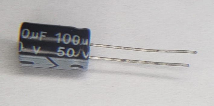
An Aluminum Electrolytic Capacitor
Due to their construction, aluminum electrolytic capacitors suffer from a problem known as leakage current. Leakage current occurs because the insulator in the capacitor is not perfect, and thus some current does flow through it. To counteract this problem, another capacitor known as the tantalum electrolytic capacitor was created which has much lower leakage current than their aluminum counterparts.
Non-polarized Capacitors
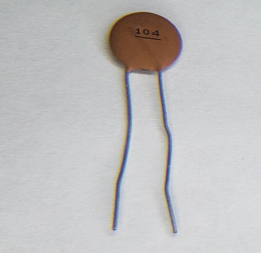
A Ceramic Capacitor
Ceramic capacitors offer higher working voltages than aluminum electrolytic capacitors, though their capacitance is much lower. Typically, you would select one or the other based on your capacitance requirements. If you need a large capacitance, then you would use electrolytic capacitors; however, if you want a small capacitance, you will tend to use ceramic capacitors.
If you look at the ceramic capacitor, you will observe three numbers printed on them. The first two digits represent the value of the capacitor, and the last digit gives us the multiplier. All we do is take the first two digits and add the number of zeros specified in the multiplier. This gives the resulting capacitance in picofarads. If you do not see any third digit, then that is the value in picofarads. So, if you see a capacitor with just “10” written, the value of the capacitor is 10 picofarads.
For example, the capacitor listed in Figure 2-17 has a marking of 104. So, the value will be 10 + 0000 which is 100 000 pF or 0.1uF.
Capacitor Schematic Symbols
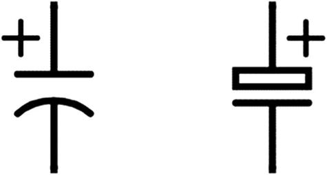
Polarized Capacitor Schematic Symbols
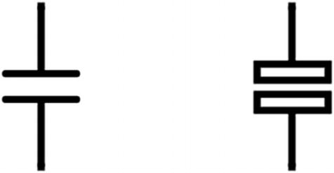
Non-polarized Capacitor Schematic Symbols
The polarized capacitor always has one lead with a plus “+” symbol next to it. Non-polarized capacitors do not have any polarization markings.
Inductors
Inductors are an especially important component that I think too many people make overcomplicated. You can learn about inductors with the use of calculus and other advanced mathematics, or you can look at inductors from the standpoint of what they are, just another component to use. Do not worry; we will cover inductors and their uses in the most practical way possible throughout this book.
Before we get more into inductors, we must understand electromagnetism. At one point or another in our life, we would have encountered magnets.
Magnets are materials that exhibit magnetism. This is to say magnets are materials that exhibit the properties of having a magnetic field. When we have the flow of a current through a conductor, we have a magnetic field that is generated. If we have a piece of wire with current flowing through it, the magnetic field will be very weak. If that wire is wrapped into a coil, a stronger magnetic field is created, and this forms the basis for an electromagnet.
A coil of wire would produce a magnetic field. However, this would still be a very weak field. We can increase the strength of the magnetic field by increasing the number of turns of wire on the coil.
To cause a large increase in the strength of the magnetic field, we introduce a material that is magnetically permeable into the core of the coil. This material is usually iron. When we do this, we now get a strong magnet that can be controlled electronically. A coil with a magnetically permeable core is called a solenoid.
We just learned about capacitors and that they can store electric charge, and we also learned that electromagnetism is the process whereby a conductor when it has an electric field running through it causes that conductor to form a magnetic field.
Inductors are devices which store electric charge. That coiled up wire we were talking about is an inductor, and for that reason, you may sometimes hear persons refer to inductors as coils.
The difference between inductors and capacitors is that inductors store their electric charge as a magnetic field. As far as the operation of the inductor goes, you can design a lot of circuits by treating the inductor as just that, a black box that stores electric charge in a magnetic field.
Inductance abbreviated (L) is measured in henries (H).
Inductors come in a vast array of packages that have different purposes. These inductors may be either shielded or unshielded. Remember we spoke about electromagnetism? Well, an inductor due to its design generates a magnetic field. This magnetic field can have undesirable effects on surrounding electronic circuits. We can design the inductor in a way that is shielded so that it will minimize the effects of interference on the environment.
Inductors are used for blocking high-frequency noise on power lines; for this reason, we call inductors used like this chokes. These are commonly found in power circuits such as inverters and motor control circuits. These chokes can be built to handle rather high current. They are also used in designing electronic filters similar to the capacitor.
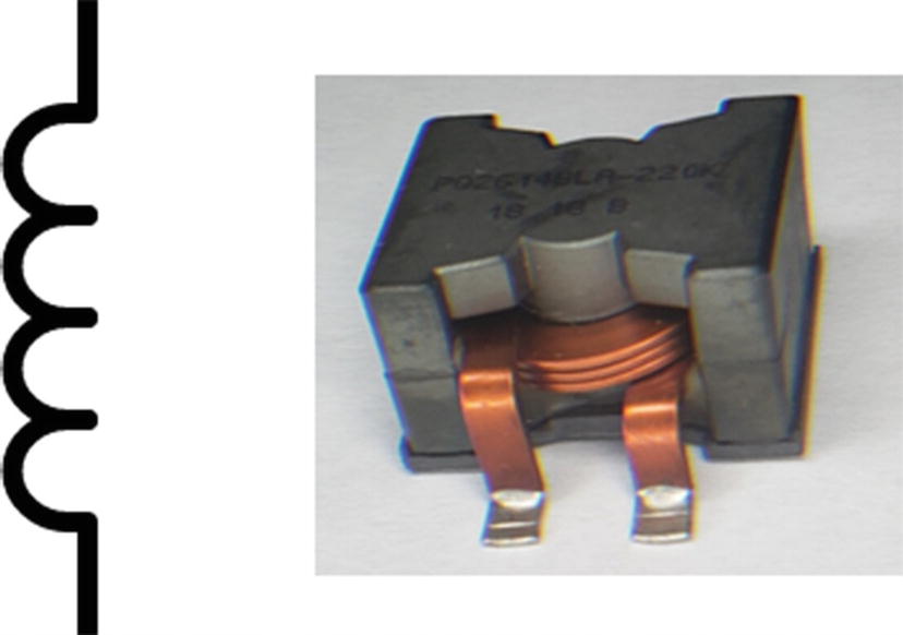
An Inductor and Its Schematic Symbol
Technology has so much advanced that a compact class of inductors called planar inductors exists. These have a remarkably high current handling capability considering their small size.
Semiconductors
In the last section, the resistors, capacitors, and inductors we looked at are known as passive analog circuit components. There are also a class of circuit components that are known as active circuit components. We will begin our discussion on active analog circuit components with a little discussion on semiconductors. I mentioned semiconductors earlier and told you we would cover them later. This section is the fulfilment of that promise.
We learned that while some substances such as silver and copper are good conductors, others such as rubber and glass are insulators. However, there is a special class of materials that are known as semiconductors.
In electronics, the two most used semiconductor materials in components are germanium (Ge) and silicon (Si). Though in recent years some other semiconductive components you will see on the market are constructed of gallium nitride (GaN) and silicon carbide (SiC).
Semiconductors conduct better than insulators but conduct more poorly than conductors. Another way of thinking about semiconductors is that they have less resistance than insulators, but more resistance than conductors. These devices however only exhibit these properties under special conditions such as with temperature or addition of other materials.
Semiconductors as mentioned earlier are not the best conductors. The conductivity of these semiconductors can be increased by adding certain impurities to them so that they become either n-type semiconductors or p-type semiconductors. The adding of these impurities is a process known as doping. When these p-type and n-type semiconductors are joined, they form what is known as a pn junction.
When you apply DC voltage between two points in a circuit for a certain operation, it is known as biasing. When you apply voltage in such a way that it can flow through a pn junction, this is known as forward bias. You can achieve forward bias by connecting a power supply to a pn junction so that the positive side of the power source is connected to the positive end of the pn junction, and the negative side is connected to the negative end of the pn junction.
However, if you apply voltage in such a way that the positive terminal is connected to the negative end of a pn junction and the negative end of the terminal is connected to the positive end of the junction, you create what is known as a reverse bias. When you reverse bias a pn junction, it has a large resistance and does not allow voltage to flow.
However, you should know a tiny amount of current flows when you reverse bias a pn junction. Also, when you apply a voltage to a pn junction, it will take a voltage above a certain amount; for silicon, it is 0.7 volts, known as a voltage drop for current to start to flow in a circuit. This voltage which causes a rapid increase in current flow is known as a knee voltage. If you apply a large reverse voltage to the pn junction, it breaks down. The voltage at which the junction breaks down is known as the reverse voltage. The peak inverse voltage is a term people use to refer to the maximum amount of reverse voltage you can apply to a pn junction before it is damaged.
Diode

A Diode
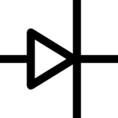
The Diode Schematic Symbol
Diodes have a negligible resistance when connected in the forward direction and a very high resistance when connected in the reverse direction. There are signal diodes, which are used for small current circuits, and power diodes, which can handle higher voltage and currents.
Light-Emitting Diode

An LED

LED Schematic Symbol
LEDs , like all diodes, have a voltage drop. This voltage drop is dependent on the type of material the LED is manufactured from.
There are two leads on an LED. The longer of these leads is called the anode. This is where you connect the positive voltage. The shorter lead is called the cathode. This is where you put your ground connection. If we look at the LED inside the plastic case, you will see that one of the leads looks larger and flat inside the case. This can also be used to identify the cathode. Additionally, on round LEDs, the plastic casing itself has a flat edge; this is yet another way you can use to identify the LED. The reason for all these markers is the LEDs do not like to be connected the wrong way. We will discuss this later when we learn how to use the LED.
Transistor
The transistor is one of the most important devices ever created. It was central to allowing the computer revolution to take place.
A transistor is formed by putting either a p-type or n-type material between a pair of opposite types. Thus, when you have two n-type semiconductors with a p-type semiconductor in between, you get an N-P-N transistor. If you have two p-type semiconductors with an n-type semiconductor in between, you will get a P-N-P transistor. This NPN or PNP junction can be thought of as two diodes connected back to back, one forward biased and the other reverse biased. A transistor’s name comes from the fact that it transfers the signal given to it from the low resistance diode to the high resistance one. In fact, the transistor is short for “transfer resistor.”

Transistor Diagram

Physical Transistor
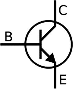
NPN Transistor Diagram
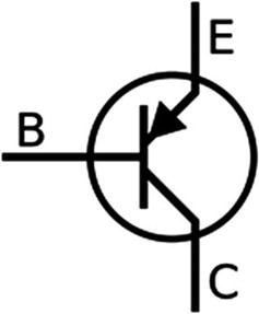
PNP Transistor Diagram
The point where a p-type and n-type conductor meet is called a junction. The junction where the emitter and base meet is called the emitter diode. Remember that a transistor can be thought of as two back-to-back diodes. The junction where the collector and base meet is called the collector diode. The emitter diode is forward biased which allows current to flow, and the collector diode is reverse biased as it does not allow current to flow. Keep this in mind as we move forward. The types of transistors discussed here due to this method of constructing them are known as bipolar junction transistors or BJTs.
Metal-Oxide-Semiconductor Field-Effect Transistors
A metal-oxide-semiconductor field-effect transistor (MOSFET) operates like a voltage-controlled resistor (VCR) . These VCRs have one input port and two output ports; the input port voltage controls the resistance between the output ports. The resistance varies nonlinearly with the voltage that is input to the device. This property allows the input port to effectively turn the MOSFET on or off. When a MOSFET is on, it has a low resistance, which is in the order of a fraction of an ohm. When you look at the datasheet of a MOSFET, you will see its RDS(On) value, which is the drain to source resistance when the device is in saturation. A MOSFET is said to be in saturation when the maximum amount of gate voltage is applied to the device, which makes the RDS(On) being very small, allowing maximum drain current to flow through the MOSFET. A lower RDS(On) value means the device will run cooler and more efficiently.

A MOSFET
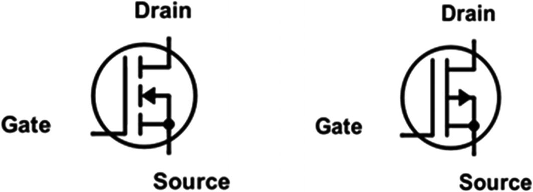
The Schematic Symbols for N-Channel and P-Channel MOSFETs
An important factor to consider is the gate threshold voltage which indicates the minimum voltage that is required to conduct current into the drain. Divert your attention to Figure 2-31.
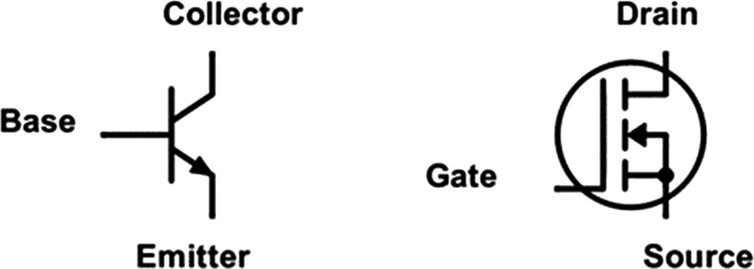
Transistor and MOSFET Side by Side
Some precautions for using MOSFETs are make sure to never exceed the gate to source voltage as you will damage the MOSFET. Also, when you are switching inductive loads (names we give to devices that are inductors), then ensure you are using a flyback diode (a diode connected across the device) to protect the MOSFET. This is something we will discuss in more detail later when we look at using motors with our device; for now just keep in mind that when you do use MOSFETs, if you are using a device which acts as an inductor such as a relay or motor, you will need to use a diode to protect the device.
Integrated Circuits
The devices we’ve looked at so far are called discrete components because each one only has one function. By contrast, an integrated circuit (IC) is a component that takes several discrete components and puts them into one device. An IC provides a lot of useful features in a compact package. By combining components we have looked at before into different circuit configurations, then we can get a desirable function for that circuit. Instead of using discrete components to achieve this function, we can make the discrete devices miniaturized and make the IC. A microcontroller, for example, as we learned in the last chapter, is a type of IC that combines many different circuit functions into one package. We will learn about different types of ICs further in the book.

Integrated Circuit Package
The type of IC shown in Figure 2-32 is a dual inline package (DIP) IC. These ICs typically range from 4 to 40 pins and usually have the pins distributed equally on the sides of the plastic case that houses everything. The pins are usually spaced 0.1 inches apart which makes DIP ICs ideal for insertion into a breadboard.
Though DIP technology is great for prototyping, today you would find that most ICs are manufactured as surface mount technology (SMT) devices, which are made for machine assembly and allow electronics to be made easier at lower cost. SMT devices are hard to work with as a beginner, though there are adapters you can use to make them fit in a breadboard.
Digital Logic
Now that we have covered basic analog electronics, we can look at digital electronics. Analog circuit components such as transistors and diodes can be combined in different ways to make digital logic circuits. The basic building blocks of all digital electronics are the logic gates; thus, our discussion on digital logic begins with a discussion on logic gates. A logic gate is a circuit configuration that takes in inputs and delivers an output state of either high or low. These high and low states correspond to voltage levels. In traditional digital electronics, we consider a high to be typically 1.8, 3.3, or 5 volts and a low to be 0 volts. These high and low voltages can vary, though for most applications these are the voltage levels we will consider. Essentially, a high is what we call a logical level “1” and the low voltage we call a logical “0”. This is known as a binary system. Binary systems use only two digits 0 and 1 to represent all their information. Digital logic circuits use these logic levels on their input and produce a binary output. For the digital logic circuits we look at in this section, this output is usually a single binary digit, which we call a bit.
A logic gate typically has two inputs and one output. Though it is possible to construct gates with any number of inputs, we will stick with two inputs to make things simple. Logic gates are available as discrete components that you can connect to your microcontroller (we will look at one such type in the next section), and when used like this, they are called glue logic, since they allow different logic circuits to be connected to work together by acting as a bridging interface to them. They are also encountered as larger parts of circuits, which we will see in later chapters in this book. In this section, we will look at some common logic gates.
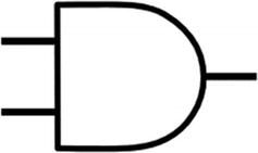
An AND Gate
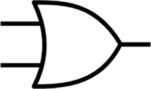
An OR Gate
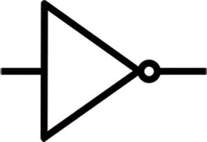
A NOT Gate
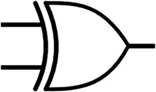
An XOR Gate

A Buffer
All these logic gates have their applications as we will see going forward.
Logic Level Conversion
When working with digital logic, it is sometimes necessary to convert from one logic level (like 1.8 volts, 3.3 volts, or 5 volts) to another. This is because different devices run at different voltages. In the early days of digital circuits, it was common to have systems run at 5 volts. Since 5 volts was the standard when intelligent devices such as microprocessors came along, they also used 5-volt logic for their operation. As such, many peripherals (special circuits on the microcontroller we will learn about later) and modules are designed to work with 5-volt systems.

Logic Level Converter
Flip-Flop
Now that we have examined discrete logic gates, we can turn to the flip-flop, which forms part of a computer’s memory. The flip-flop is the smallest unit of memory. A flip-flop can store a single bit of data in the form of either a high or low logic state. In digital electronics, there are combinational logic circuits and sequential logic circuits. Combinational logic circuits have their outputs changed as soon as their input is modified; take the AND gate, for example, as soon as the inputs of the gates are changed; the output will change immediately in response to that input. The reason the flip-flop can be used as computer memory is that it falls into the category of a sequential logic circuit. Such circuits only change their output state if you do so intentionally, regardless of what you do on the input. This output is usually changed in response to not only the current inputs but also on the previous inputs to the device. The flip-flop is the basic building block of sequential logic circuits.
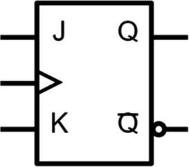
A JK Flip-Flop
The pin we see with the triangle on the flip-flop in between the J and K pins, which are input pins, is the clock pin; the clock pin takes a clock input. A clock can be thought of as a logic level signal that alternates between a high and low logic level state. The state when the clock transitions from low to high is called the rising edge of the clock, and the state when the clock transitions from high to low is called the falling edge of the clock. We also have output pins which are Q and !Q (not Q). If J and K are in a logical HIGH state and we apply a clock signal, then the outputs at Q and !Q will change state. If both J and K are in a LOW logical level state and we apply a clock pulse, then there will be no change on the output.
JK flip-flops are known as universal flip-flops, and they are used in devices like shift registers, pulse-width modulation (PWM) circuits, and counters, among other types of circuits we will learn about in this book.
Registers and the Shift Register
The flip-flop forms the foundation of the basic unit of computing memory. Another term we use to refer to a basic unit of computer memory is the register. Registers are used to store and manipulate data within the computer. Registers utilize flip-flops for data storage, and thanks to this, we can read and write from them easily. For ease of understanding, you can think of a register as a black box that stores a bit of data, and internally this black box uses a flip-flop to accomplish this task.
One type of register that you will encounter is the shift register . A shift register can store a sequence of either 4 or 8 bits. The shift register has a sequence of flip-flops that are connected in such a way that when a pulse of a clock is applied to the device, bits are moved from one flip-flop to the next.
To accomplish this, a shift register usually has a chain of D flip-flops. A D flip-flop can be thought of as a JK flip-flop with only one input, which makes the flip-flop easier to use; however, it requires more logic circuits to realize its implementation. Within a shift register, we call each D flip-flop a latch. The difference between a latch and a flip-flop in the strictest sense is that a latch is level triggered, whereas a flip-flop is edge triggered. What this means is that the latch is asynchronous, changing the inputs as soon as the inputs change the logic level, whereas the flip-flop depends on the state of the clock signal (using either the rising or falling edge of the clock) to change its input.
We say something is level triggered when it responds to a transition of a voltage level on the input of the device, which can be a high or low logic level. An edge-triggered device on the other hand responds to the edges of the clock signal, and it may be triggered by the rising edge or falling edge of the clock signal.
Within a shift register containing the latches, the output of one latch is connected to the input of another latch, and data can be fed into the shift register serially (one bit at a time), or it can be fed in parallel (all the bits at the same time).
Serial In Serial Out (SISO)
Serial In Parallel Out (SIPO)
Parallel In Parallel Out (PIPO)
Parallel In Serial Out (PISO)
Bidirectional shift register
Each type of shift register has its own application. Today, many shift registers are integrated within ICs, so they are not frequently used as discrete components.
Multiplexers and Demultiplexers
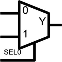
A Multiplexer
The multiplexer has two inputs labeled 0 and 1 or A and B, and another input line called SEL0, as well as an output line Y. According to the value of the input lines, the multiplexer assigns a value to the output. If the selector line is low, then line 1 will be on the output. If the selector line is high, the output will reflect the value on the line 0.
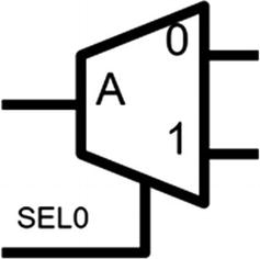
A Demultiplexer
The demultiplexer has an input A or F and two outputs 0 and 1 or A and B, as well as a selector line, SEL0. The binary pattern on the input line will be converted to values on the output lines. When the select line is low, then the input at A will be on the line 0, and when the select line is high, then the multiplexer will assign the input at A to line 1.
Conclusion
In this chapter, we covered basic electronics, with a focus on some of the actual components that are commonly used. We looked at passive analog devices, as well as semiconductors, diodes, transistors, and MOSFETs. We also looked at some of the components of digital electronics. Armed with the basics of digital electronics, you will better understand microcontrollers when you work with them later. I hope in this chapter you will have learned that electronics concepts build upon one another. Diodes and transistors, though they are analog components, can be combined to form digital building blocks of which microcontrollers are comprised; the knowledge learned here will seem to be abstract for now, but I assure you as we learn about the various peripherals on the microcontroller, then we will understand how useful this information is. The information here will serve you on your microcontroller journey.