One of the main strengths of microcontrollers is their ability to digitize the analog information we’re so familiar with working with, like temperature, humidity, and light intensity. We can take these analog sensor readings and convert them into digital form as signals that we can analyze and manipulate. Converting analog signals into digital signals is a hallmark for microcontroller devices, as many applications of the smart devices that utilize microcontrollers will monitor sensors and then perform some action based on that data. Analog to digital conversion is an essential topic for anyone interested in microcontrollers.
In this chapter, we look at analog to digital conversion, then look at some sensors we can get data from using this method. The sensors we will use include a potentiometer, a photoresistor, and a temperature sensor.
Analog to Digital Conversion
Any decent microcontroller will be outfitted with analog to digital conversion modules. Analog to digital conversion (ADC) modules convert the information presented to them into a binary representation that the microcontroller can manipulate.
Our physical world is analog in nature. Take your phone’s recording system: you speak into your phone’s microphone, and the signal received is analog. The microphone must then convert this analog information from your voice into a digital signal representation that can be interpreted by your microcontroller. One application of this would be in voice recognition systems where a microcontroller in your device needs to listen for a “wake-up word.” A “wake-up word” is a word or phrase you can use to get the attention of your computing device. The microcontroller would need to convert your voice into a digital form so that it can search for the word, which would wake up the device from sleep. Most smartphones also incorporate features that filter out background noise or amplify voice signals. Using the ADC module of a microcontroller, you can easily filter out noise from the audio coming into the microphone. This type of filter though is not like the hardware filters we learned about in Chapter 2 but is in fact a digital one which operates in software. Their function however is similar to the filters you learned about previously.
As we learned in Chapter 2, analog circuits are known as continuous circuits; thus, the signals produced by them are continuous in nature. When we say a signal is continuous, we mean that it is characterized by smooth transitions between points in the signal with a variation in time. A digital signal, being produced by digital circuits, as we learned has a discrete nature. For our purpose, these can be thought of as a digital representation of a continuous signal.
Let’s first take a closer look at what’s meant by a signal. A signal can be thought of as energy that we can use to extract information. Within the context of microcontroller electronics, signals take the form of a voltage or current that is produced by a sensor. The signal that is produced by a sensor is usually not in a form we can directly get information from, as we lack the faculties to process sensor information. The microcontroller would need to read the sensor for us, then via a display of some sorts relay the information in a way we can understand. The microcontroller can also take this information and perform some action. For example, a digitally controlled oven may have a thermocouple sensor to read the temperature inside the oven. The microcontroller would need to switch off a heater when the temperature inside the oven reaches a preset temperature. This is just one application where an ADC module may be utilized.
ADC Hardware
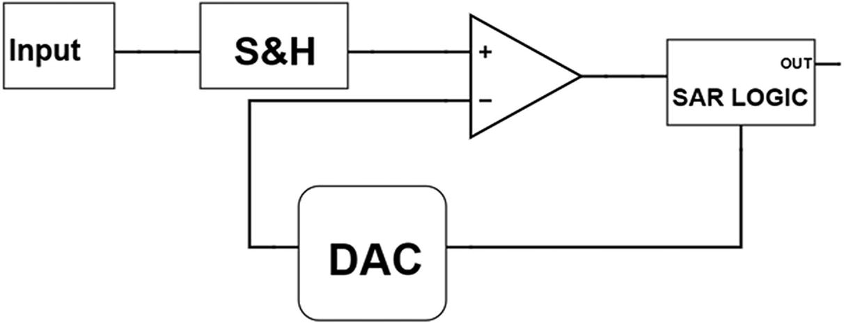
Successive Approximation Circuit
The circuit operates by first taking an input from the microcontroller pin. Since there is only one ADC module on a typical microcontroller, using a multiplexer circuit, we can route the voltage from several pins to the ADC module within the microcontroller. This is because one module can only read one pin at a time, and many times, we may need our microcontroller to read several sensors.
To ensure that the ADC functions correctly, a snapshot of the voltage of the microcontroller pin is taken. This snapshot is needed to be taken since the sensor would keep continuously outputting data, and the ADC circuit would need time to perform the conversion. This snapshot is taken at that point in time the ADC module is invoked to perform the conversion by the microcontroller. To take the snapshot, a capacitor is used because, as we learned before, a capacitor can store voltage. The capacitor will be charged up to the same voltage value as the pin we want to read the voltage of. For example, if a sensor outputs 3.7 volts, then quickly outputs 3.9 volts, then 4.0 volts, we need some sequence to effectively digitize all these readings. This is because a lone ADC module lacks the ability to perform parallel conversion. The ADC module would first need to take the 3.7 volts, convert it to digital form, then the 3.9 volts, and so forth.
This voltage that the capacitor is charged to will be what we will use to perform the successive approximation procedure on the microcontroller. We call this front end on the ADC module with the capacitor a sample and hold (S&H) circuit.
Once there is a voltage on the S&H circuit, the comparator working together with the ADC circuit comes into action. The combination of these two circuits will keep cutting the voltage at the input in half. When we say the voltage at the input, we are really talking about the snapshot voltage. The process will continue until we reach as close to the input value as the combination of these circuits will allow.
When discussing ADC, a word that comes up frequently is resolution. Let’s take a closer look about what is meant by resolution. The ADC module has a range of values that it can use to represent the converted signal. This value is represented as a number of binary bits which is output by the module. Essentially, the smallest voltage which causes a bit change is what we refer to as the resolution. According to the resolution of the ADC, the ADC module will have a certain number of voltage steps that it can use to represent the voltage measured. The greater the number of voltage steps, the greater the resolution of the ADC module.
To output the information, the ADC circuit will manipulate the most significant bit (MSB) down to the least significant bit (LSB) of the binary number which is to be output by the module using the conversion value from the comparator and DAC. This is to try to match the voltage value read on the input as closely as possible and represent it in binary form. This output value is of course limited by the resolution of the DAC within the ADC module. This is because the amount of times the voltage can be cut is dependent on the DAC resolution. This value is then output from the ADC module so that it can be read and manipulated by the CPU.
When selecting a microcontroller for your application, sometimes the resolution of the ADC can be a deciding factor in selection of your device. The resolution required to read a temperature or light sensor, for example, may not be as important. However, if we need to build a circuit for voice recognition, you will need high resolution to have a functional circuit. ADC circuits onboard the microcontroller typically have a resolution of about 8 to 16 bits. For most sensor reading applications, this is sufficient, and if greater resolution is required, for example, in specialized medical applications, an external ADC IC is used.
Going Deeper into ADC
At this point, we will look at some additional terms you are likely to encounter when discussing ADC. The first thing we need to talk about when discussing ADC is sampling. As we explained in the previous section, in order for the ADC module to have time to process the read value, a snapshot of the voltage must be taken. Sampling is the name given to the number of snapshots we can take over a period of time. When we talk about sampling in analog to digital conversion, what we are talking about is the ability of the ADC module to replicate the signal it is analyzing and create a digital equivalent as close to the original as possible. The more samples a digital to analog converter can capture, the more accurate the digital representation of the original signal will be.
A dilemma you may arrive at is trying to determine the optimal amount of samples we need to take to have a decent representation of the signal we are sampling. If we take a lot of signals, then our module will be slow and may not have the response time we need for our application. On the other hand, if we take too few samples, we will have a fast conversion; however, we may not have an accurate representation of the original signal. A special sampling rate known as the Nyquist sampling rate is the benchmark that is used to determine the minimum sampling time.
The Nyquist sampling rate is stated as having the minimum sampling rate being at least twice the highest frequency of the signal we are trying to sample. For example, if a signal is expected to have a maximum frequency of 10 kHz, then we must have a minimum sampling rate of 20 kHz. Another way of saying it is that the sample and hold circuit must take 20,000 snapshots a second to adequately measure the signal.
ADC modules also have a data sampling rate that is usually measured in the number of samples per second (SPS) the ADC module is capable of measuring. Typically, we would see the manufacturer specifying the sampling rate in kilo samples per second (kSPS) or mega samples per second (MSPS).
Another facet we can look at within ADC conversion is that of quantization. Quantization is the name given to the process of mapping the value of input voltage to the ADC to an output value that the ADC is capable of producing. A 10-bit ADC module, for example, will have steps from 0 to 1023. We call this value from 0 to 1023 the quantization level of the ADC. An 8-bit ADC will have quantization levels from 0 to 255. This quantization is the name given to the rounding of values that are equal to the voltage we tried to measure on the pin. What this means is that in the strictest sense we can redefine resolution to mean the measure distance between two adjacent quantization levels.
The Potentiometer
The Potentiometer
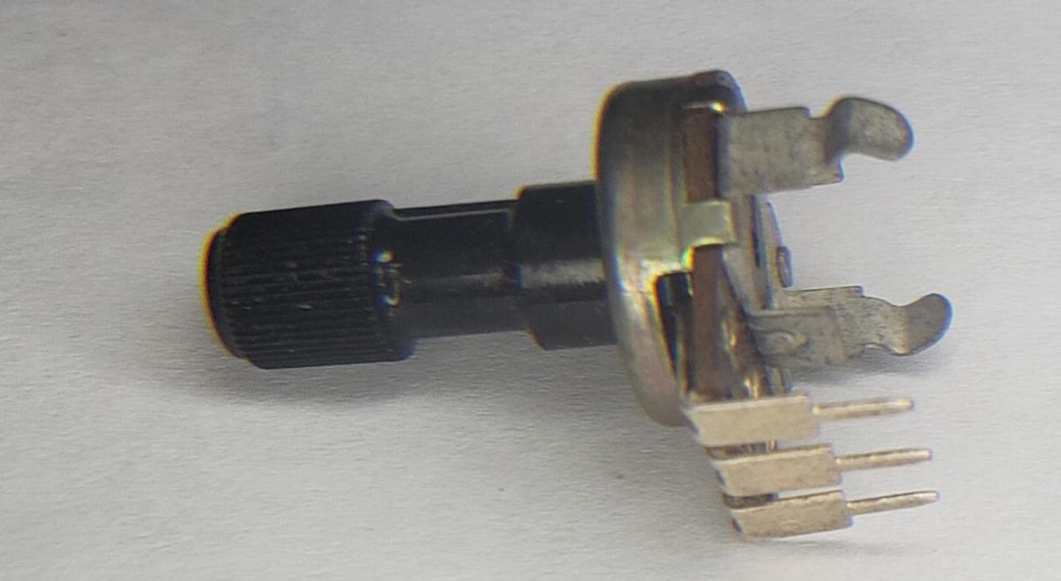
The potentiometer may come in varying form factors; however, if we look at its mechanical construction, we will observe that they are all three-pin devices with a turning mechanism at the top to allow for adjustment. Sometimes, you may see a device looking like a potentiometer with five or more pins protruding from it. This is not a potentiometer but is a rotary encoder and functions differently.
Of the three pins on the potentiometer, one pin is connected to the supply rail, the other pin is connected to the ground supply, and the third pin is connected to the input pin of the microcontroller. When you adjust the knob on the potentiometer, what you are doing is varying the voltage on the analog input from 0 volts to VDD. This can typically range from 0 volts to 3.3 or 5 volts.

The Voltage Divider
The voltage divider as shown in Figure 6-3 will output approximately half of the voltage that is present on VCC. So if VCC is 5 volts, then the output of the voltage divider will be 2.5 volts. The output of the voltage divider is determined to be the voltage measured at the center point of both resistors. This is what voltage dividers do; they output a fraction of the input voltage that is present on the input. The output of the voltage divider is not arbitrary but is determined based on the values of the resistors that make up the divider circuit. Once we know the value of the resistors, we can use what is known as the voltage divider formula to calculate the output. This formula is useful when we need to get a specific voltage output using resistors.
To calculate the output of the voltage divider, we use the formula which is given as
Vout = Vin(R2/(R1 + R2)
We know that the divider circuit in Figure 6-3 would give half the input voltage; however, if we wanted to calculate the same mathematically, we can use our voltage divider formula. If we wanted to calculate our Vout, we could use the formula and input the values of our Vin, R1, and R2. When performing our calculation, we take R1 to be the top resistor and R2 to be the resistor on the bottom, and we get
Vout = 5v (1 / (1 + 1) = 5v x 0.5 = 2.5
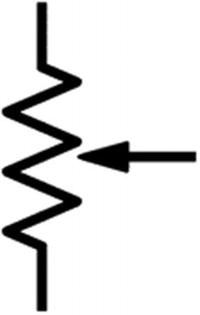
The Potentiometer Schematic Symbol
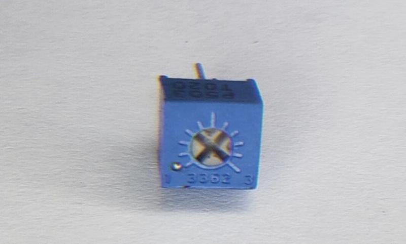
The Trimmer Potentiometer
This version of the potentiometer is called a trimmer potentiometer or a trim pot. The function is the same as the regular potentiometer; however, it is designed to be hidden in the end product and adjusted by the manufacturer or service personnel, not by the end user of the product. These are easy to identify because whereas a regular potentiometer has the adjustment knob extended out from the device, these must be adjusted by a screwdriver in order to change their values.
Analog to Digital Conversion in CircuitPython
board – The board module contains the pin constants for the board we are using.
analogio – This is the module that contains all the classes that provides access to both analog input and output functions we are using. This is the module that allows us to read analog data from our analog capable pins.
time – The time library contains functions that will allow the microcontroller to use time-related functions. The sleep method is the one we will utilize to aid with timing for our microcontroller.
Some boards may not support some functionality such as analog input functionality particularly if their firmware is in beta; for that reason, it is best to check the release notes for the board you are using.
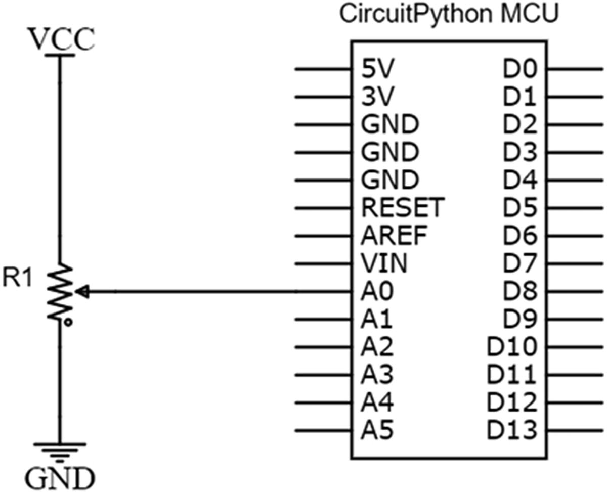
ADC with MCU Schematic
MCU with Potentiometer
ADC Circuit Connection Tips
- 1.
Connect a jumper wire from the A0 pin on your microcontroller to a socket on the prototyping area of your breadboard.
- 2.
Connect the center lead of the resistor to another socket in the same row of the breadboard used in step 1.
- 3.
Take a jumper wire and connect it from one lead of the potentiometer to VCC.
- 4.
Connect the last lead of the potentiometer to the ground with a jumper wire.

MCU with Potentiometer Breadboard
Once you have your circuit setup, we run the program as shown in Listing 6-1. Remember to check your connections and ensure they are in accordance with your schematic, or else you risk damaging your board circuit components. For that reason, I always recommend you connect your circuits with the power off, then power it on before writing your program to test it.
CircuitPython with Potentiometer Program
MCU with Potentiometer Program
The first thing we do is import the CircuitPython libraries we need to control the board. These are our usual imports of our time and board libraries. At (1) we import the AnalogIn object from the analogio module. This is the library that allows us to perform analog functions. The next step in our program at (2) is to create a pin object that will allow us to read the specific analog pin we are working with. In this case, we are working with pin A0 on the board, and we name it analog_in.

MCU with Potentiometer Output
When we adjust the input of the potentiometer, we see that the output goes from 0 volts to around 3.3 volts, and this value is printed to the serial terminal.
Photoresistor
One sensor that we will now be able to use thanks to this ability to read analog sensors is the photoresistor. A photoresistor is a type of resistor that changes resistance based on the amount of light that is falling on them. When there is no light falling on the photoresistor, it has an extremely high resistance in the order of hundreds of kiloohms. However, when light falls on the photoresistor, the resistance drops to a few hundred ohms. To create a program to read the photoresistor, we will need to create a voltage divider circuit. This voltage divider circuit will consist of the photoresistor with a regular resistor. The output of the circuit will then be read by the microcontroller to determine change in the light levels of the photoresistor.
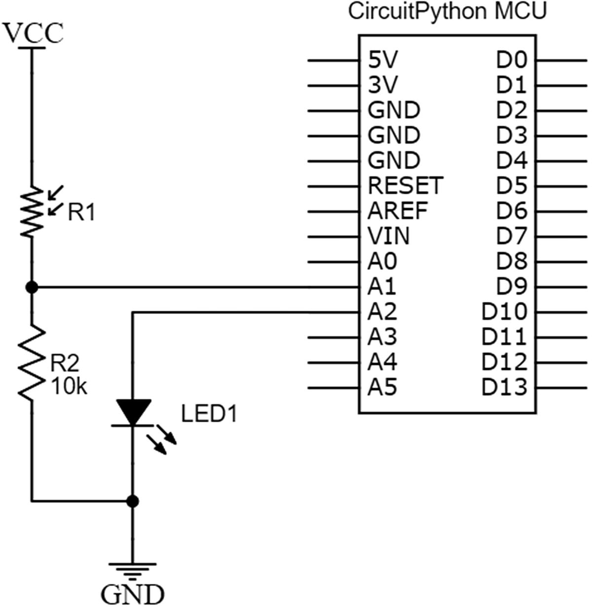
Photoresistor with MCU Schematic
MCU with Photoresistor
Photoresistor Circuit Connection Tips
- 1.
Connect a jumper wire from the A2 pin on your microcontroller to a socket on the prototyping area of your breadboard to one lead of the LED.
- 2.
Connect the other lead of the LED to the ground with a jumper wire.
- 3.
Take a jumper wire and connect one lead of the photoresistor to VCC.
- 4.
Connect the other lead of the photoresistor to one lead of the 10k resistor.
- 5.
Take a jumper wire and connect the other lead of the 10k resistor to the ground.
- 6.
Run a jumper wire from the intersection of the resistor and photoresistor to pin A1 on your microcontroller.

MCU with Photoresistor Breadboard
Now that we have our circuit setup, we can write some code!
Photoresistor with CircuitPython Program
MCU with Photoresistor Program
This program does a lot of things. Let’s look at them to see what happens. At the top of the program, we import our board, time, analogio, and digitalio libraries. At (1) we create an adjustValue variable that is used to aid in the reading of the photoresistor. Our next step is to create an object that represents our real-world LED at (2) and set it to an output at (3). We then create an object to represent our photoresistor at (4). At (5) we then take a single reading from the photocell and store that value. This is the value of the ambient light that currently exists.
Note that after taking our reading, we must use the deinit method at (6) to allow our pin to be used in other parts of the program. If we don’t do this, then we won’t be able to use the pin in our super loop.
Inside our super loop at (7), we continually read the photoresistor value. There is a conditional that checks to see if there is darkness on the LED. If there is darkness, the LED will be turned on, and when there is light, we will turn the LED off.
Save the program and run it. You will observe that when you cover the photoresistor with your hand, the LED turns on; however, when the LED is at ambient brightness or brighter, the LED will not be lit.
Temperature Sensor
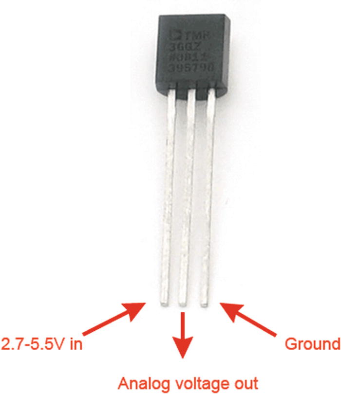
TMP36 Temperature Sensor Credit: Adafruit, adafruit.com
The TMP36 temperature sensor device has three pins. One is the VCC pin which we connect to our positive supply. There is also a GND pin which we connect to our ground and an analog voltage out pin which is read by the microcontroller. Depending on the value of the voltage at VCC, the microcontroller can then do some calculations to determine the temperature we are reading.
The sensor works from 2.7 to 5.5v, making it a very versatile sensor as it works with all common microcontrollers equipped with an ADC module. It is capable of being used with CircuitPython-based MCUs that are 3.3-volt devices, which fall within the voltage range of the device. The temperature sensor can take measurements from –50 degrees Celsius to 125 degrees Celsius which is a good range for most projects you will undertake.
Temperature Sensor with MCU Schematic
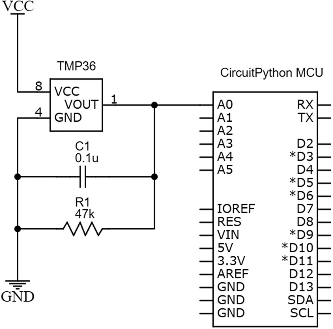
Temperature Sensor with MCU Schematic
Temperature Sensor Circuit Connection Tips
- 1.
Connect a jumper wire from the VCC pin of your TMP36 temperature sensor to the positive rail of your breadboard.
- 2.
Take a jumper wire and connect the ground pin of your sensor to the ground rail of your breadboard.
- 3.
Connect one lead of the 47k resistor to the output pin of the TMP36 sensor and connect the other lead of the resistor to the ground pin of the sensor.
- 4.
Connect one lead of the capacitor to the ground pin and the other lead to the output pin of the TMP36 sensor.
- 5.
Run a jumper wire from the output pin of the temperature sensor to pin A0 on the MCU running CircuitPython.
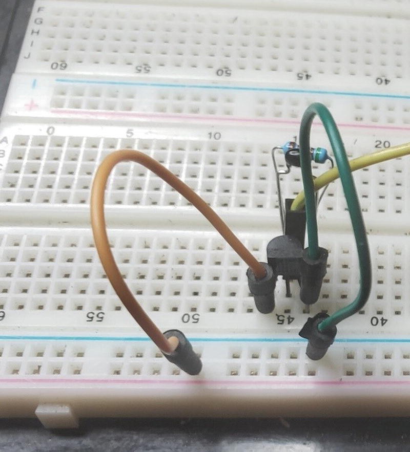
Temperature Sensor with MCU on Breadboard
Temperature Sensor with CircuitPython Program
MCU with Temperature Sensor Program
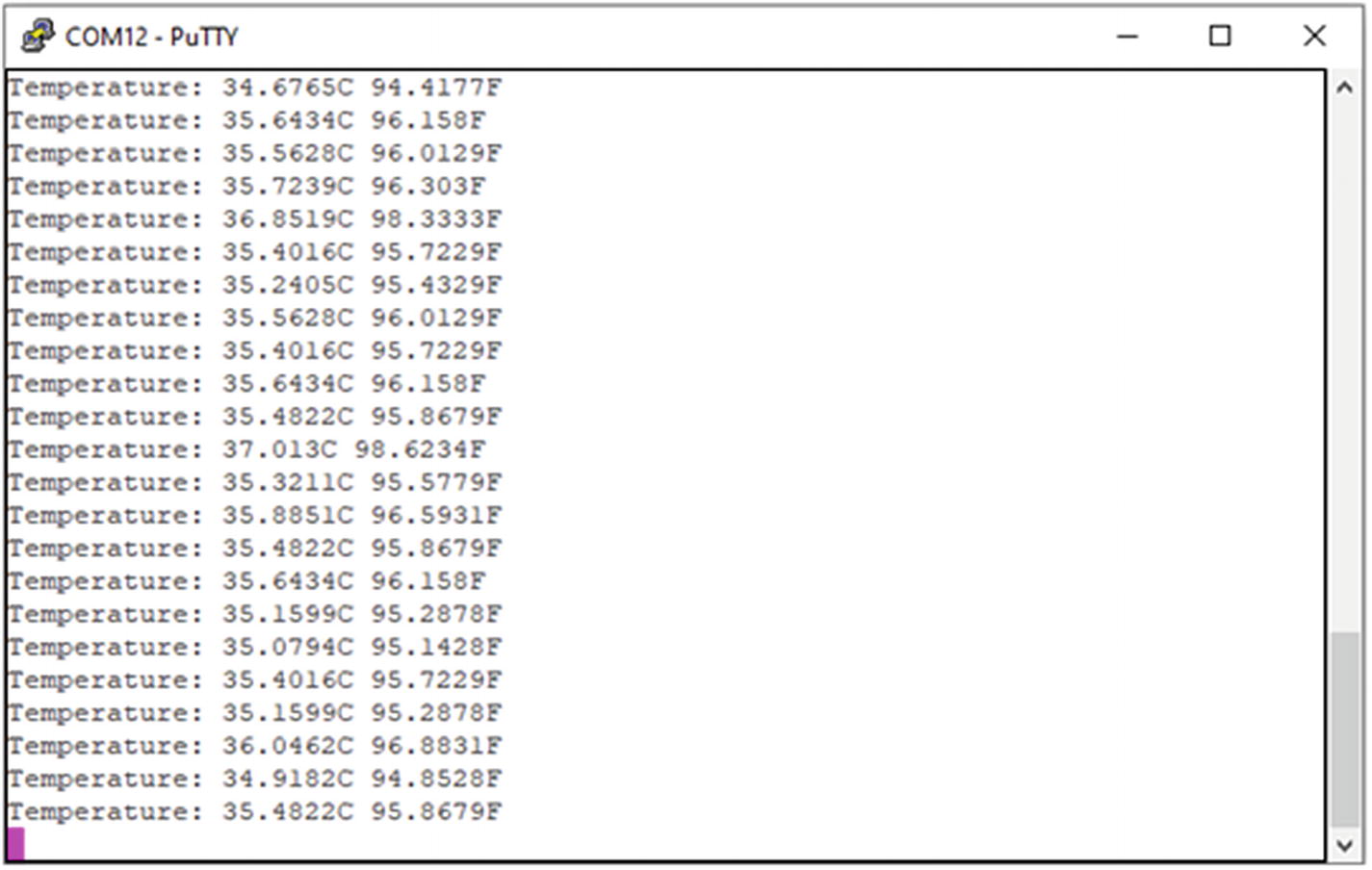
Temperature Sensor Output
Conclusion
In this chapter, we covered the basics of analog to digital conversion. We looked at how microcontroller ADC circuits work in hardware, and along the way of learning how these circuis function we discovered how potentiometers, photoresistors and voltage dividers work. We also learned how to use CircuitPython with analog inputs. Using this information, we were able to read a temperature sensor and output the information to a serial terminal. With the knowledge gained here, hundreds of sensors are now at your disposal.