10
LED Fader Project
This is the first of three projects designed to make use of Python and the GPIO pins to control the color of light coming from an RGB LED. The project combines the use of the guizero library to create a user interface and the gpiozero libraries’ PWM feature to control the brightness of the three channels of the LED (red, green, and blue).
Figure 10-1 shows the LED hardware built onto breadboard and Figure 10-2 shows the user interface used to control it on your Raspberry Pi.
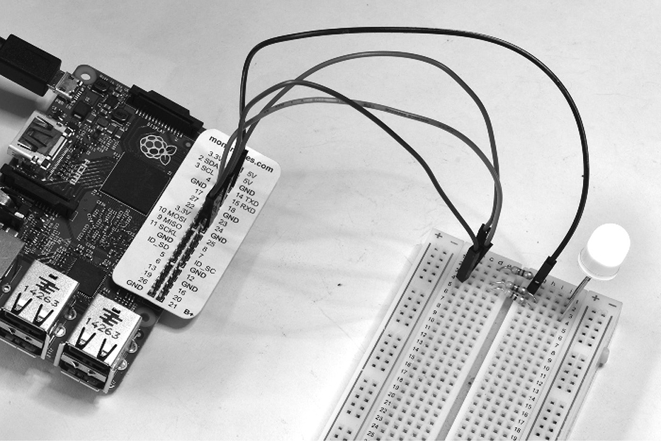
Figure 10-1 An RGB LED connected to a Raspberry Pi.
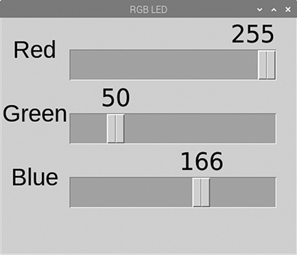
Figure 10-2 A guizero user interface for controlling the LED.
What You Need
To build this project, you will need the following parts. Suggested part suppliers are listed, but you can also find these parts elsewhere on the Internet.
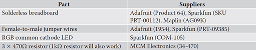
The Project Box 1 for Raspberry Pi from MonkMakes includes all these parts. You can also use a Raspberry Squid, an RGB LED with built-in resistors that can be plugged directly into the GPIO pins of the Raspberry Pi. You can find instructions on making your own Raspberry Squid here: https://github.com/simonmonk/squid.
Hardware Assembly
The breadboard layout for the project is shown in Figure 10-3.

Figure 10-3 The breadboard layout for an RGB LED.
It will keep things neater and prevent any accidental connections between the leads if you shorten the resistor leads so that they lie flat against the surface of the breadboard.
The RGB LED will have one leg that is longer than the others. This is the “common” lead. When you buy your RGB LED, make sure that it is specified as being “common cathode.” This means that the negative terminals of each of the red, green, and blue LED elements are all connected together.
Software
The software for this project has some similarity with the experiment in Chapter 9, where you controlled the brightness of a single red LED by typing in a value between 0 and 100. However, in this project, instead of entering a number, guizero is used to create a user interface that has three sliders in a window. Each slider controls the brightness of a different channel, allowing you to mix red, green, and blue light to make any color.
Run the program and after a few moments the window shown in Figure 10-2 will appear. Try adjusting the sliders and notice how the LED color changes. LEDs with a diffuse body mix the colors much better than those with a clear body.
You can find the program in the book examples as the file 10_01_RGB_LED.py. Rather than list the whole program here, open it up in Mu while I go through the code in sections.
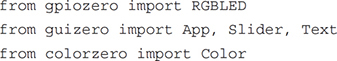
The program starts with the usual imports.
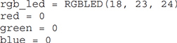
The gpiozero class RGBLED is used to associate pins 18, 23, and 24 with the red, green, and blue LED channels, respectively, and three variables red, green, and blue defined and given initial values of 0.
Next, we have three functions, red_changed, green_changed, and blue_changed. Each will be called when their respective slider is moved. Here’s the code for the red channel:
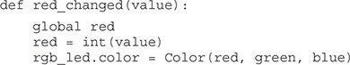
This first sets the value of the global variable red to be the parameter passed to it after first converting it to a number. The RGBLED’s (rgb_led) color is then set to a new Color created from the current red, green, and blue constituents. These are standard color values specified as red, between and blue components, each between 0 and 255.
Here is the code for the user interface itself, which is arranged in a grid:
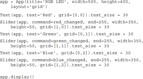
Note how the method text_size is used to make the text bigger. The command parameter of the Sliders links to the appropriate color change function.
Summary
This is a simple project to get you started with some GPIO programming. In the next chapter, you will use a display module that uses a I2C serial interface to connect to the Raspberry Pi and make a digital clock.