3
2D Shapes

You’re now familiar with a good collection of basic OpenSCAD instructions for modeling simple 3D shapes, and you’ve seen operations that can transform those basic shapes into more complex designs. This chapter will teach you how to create and combine 2D shapes in order to build even more sophisticated 3D designs.
We’ll start by showing you how to draw basic 2D shapes, and then we’ll describe how to build on those basic 2D shapes to create elaborate 3D designs. Using 2D shapes will allow you to create designs that are not possible to build with the 3D shapes and operations you’ve learned so far. In addition, knowing how to create 2D shapes is useful when you’re designing for other digital fabrication techniques, such as laser cutting, though that’s beyond the scope of this book.
Drawing Basic 2D Shapes
As with 3D shapes, you can build complex 2D shapes based on a few built-in 2D primitives, called circle, square, and polygon.
Drawing Circles with circle
The circle command allows you to draw a 2D circle by specifying its radius, like the sphere command from Chapter 1. For example, the following statement draws a circle with a radius of 20 units (Figure 3-1):
circle(20);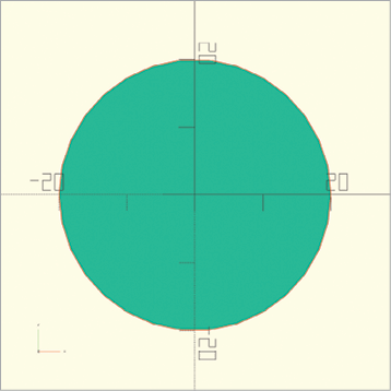
Figure 3-1: A rendered circle with a radius of 20 units
Clicking the Preview button renders your circle with a slight depth (Figure 3-2).
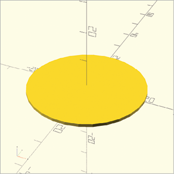
Figure 3-2: A previewed circle with a radius of 20 units
However, 2D shapes have no depth. They exist only in the xy-plane. To see 2D shapes in their true form, without depth, use the Render button. (Note that it’s not possible to mix 2D and 3D shapes in Render mode.) Because 2D shapes have no depth, it’s often easiest to create 2D designs by using the Top-view icon on the toolbar (Figure 3-3).
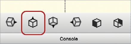
Figure 3-3: Top-view icon
Drawing Rectangles with square
The 2D square command, which draws rectangles, specifies x and y dimensions as a single vector parameter. The following statement draws a rectangle that extends 25 units along the x-axis and 10 units along the y-axis (Figure 3-4):
square([25, 10]);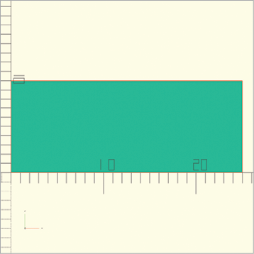
Figure 3-4: A rectangle with a width of 25 and height of 10 units
Use the square command to indicate that you want to draw a rectangle, followed by a set of parentheses. Within the parentheses, put square brackets, and then within those, enter the dimensions of the square, separated by a comma. This 2D vector requires only x and y dimensions, as opposed to the 3D vector (x, y, and z) required by the 3D cube shape. The first number in the vector represents the width of the square along the x-axis. The second number in the vector represents the length of the square along the y-axis.
Remember that you’ll need to click the Render button to see the rectangle as a 2D shape.
Drawing Polygons with polygon
If you want to create a 2D shape that isn’t built into OpenSCAD, you can create your own 2D shapes with the polygon command.
The following statement uses the polygon command to draw a triangle with vertices at [0, 0], [10, 0], and [10, 10] (Figure 3-5):
polygon([ [0, 0], [10, 0], [10, 10] ]);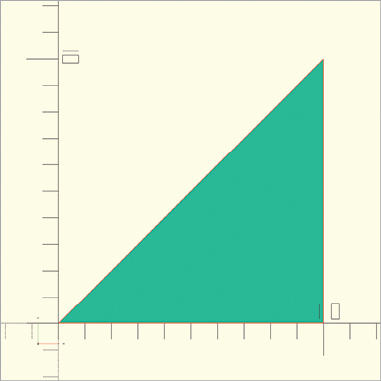
Figure 3-5: A triangle with three vertices
A polygon is defined by a list of the shape’s corners, called vertices. Each vertex in this list is a vector containing the coordinates of a corner point in the polygon. Group each vertex as a vector within square brackets, then add an extra set of brackets around the entire list of vertices to organize the collection as a vector of vectors.
Be sure to list the vertices in order, as though you were walking around the edge of the polygon (in either direction). Also, you don’t need to specify the starting point twice; OpenSCAD will finish the polygon for you automatically.
Since polygons can have any number of vertices, you can create increasingly complex shapes, like this one with eight vertices drawn with the following statement (Figure 3-6):
polygon([
  [ 0,  0], [20,  0],
  [20,  5], [ 5,  5],
  [ 5, 10], [20, 10],
  [20, 15], [ 0, 15]
]);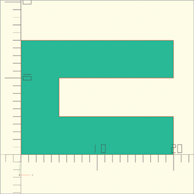
Figure 3-6: A more complex polygon with eight vertices
Drawing Words with text
Another way to use 2D shapes in your designs is to create symbolic patterns, such as words. Using textual elements in your designs can be useful for personalization. You may also want to use emoji fonts to access pre-drawn symbols or simply stamp a version or serial number onto your design.
Use the text command to draw text shapes in OpenSCAD. Text in OpenSCAD (as in other programming languages) is considered a string of characters. Since a string of characters can be arbitrarily long, quotation marks (" ") are used to indicate the beginning and end of the text string. Text strings can contain letters, punctuation, numbers, and (if the font used supports Unicode) emoji characters.
This statement creates the string "Hello, OpenSCAD" (Figure 3-7):
text("Hello, OpenSCAD", size=10);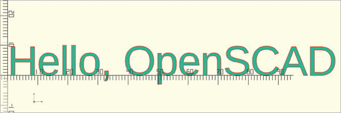
Figure 3-7: Creating a 2D text shape
Follow the text command with parentheses containing a string of characters. The strings should start and stop with double quotes (" "). The parentheses can also contain an optional size parameter, which sets the text size to 10 in this case. Notice in Figure 3-7 that the tallest letters in the string reach the first tick mark (which represents 10 units) on the y-axis.
The size parameter is optional for text shapes. If you leave off the size parameter, the default text size is 10. Another optional parameter for drawing text shapes is font. You can also use the optional font parameter to draw text in any font installed on your computer. The following statement draws a string of text in Courier font (Figure 3-8):
text("Hello, OpenSCAD", font="Courier");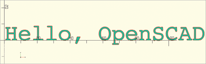
Figure 3-8: Changing the text shape’s font to Courier
Fonts that support Unicode characters will often contain emoji. You can draw any character supported by the font, including emoji shapes (Figure 3-9):
text("♕", font="Arial Unicode MS");
Figure 3-9: Using text to draw a crown emoji
It’s also possible to draw numeric values with the text command. If you want to create a shape with a numeric value (Figure 3-10), be sure to convert the value to a string with the str function:
text(str(123), size=20);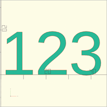
Figure 3-10: Drawing a text shape with numbers
Rather than putting the number between quotation marks, apply the str function to a numeric value in order to turn it into a string. This is particularly helpful when the numeric value is stored in a variable, as we’ll see in Chapter 4.
Applying Transformation and Boolean Operations on 2D Shapes
You can apply the same transformation and Boolean operations you learned in Chapters 1 and 2 to 2D shapes—and it’s done pretty much the same way as when you apply them to 3D shapes. The only difference is that instead of requiring 3D vectors, the translate, mirror, and resize operations require 2D vectors containing x- and y-coordinates, and the rotate operation requires only a single angle of rotation (for the z-axis).
For example, the following design uses translate, difference, and rotate to draw an askew rectangle with three circles cut out of it (Figure 3-11):
rotate(30) {
    difference() {
        square([120, 40]);
        translate([20, 20]) circle(15);
        translate([60, 20]) circle(15);
        translate([100, 20]) circle(15);
    }
}
Figure 3-11: Transformation and Boolean operations on 2D shapes
Just as with the 3D shapes, the order in which you apply transformations and Boolean operations on a 2D shape will affect the arrangement and placement of the resulting shape. Consider the difference between subtracting a circle from a square versus subtracting a square from a circle. The following difference operation subtracts a circle from a square (Figure 3-12):
difference() {
    square([5, 5]);
    circle(5, $fn=50);
}
Figure 3-12: Subtracting a circle from a square
And this difference operation subtracts a square from a circle (Figure 3-13):
difference() {
    circle(5, $fn=50);
    square([5, 5]);
}
Figure 3-13: Subtracting a square from a circle
Extruding Shapes Vertically with linear_extrude
You can’t 3D-print 2D shapes directly, but you can use them as building blocks for creating 3D shapes (which can then be 3D-printed as physical objects). This section describes two of OpenSCAD’s powerful operations for creating 3D shapes from 2D shapes.
The linear_extrude operation takes a flat shape and “lifts” it up along the z-axis while building walls corresponding to the shape’s initial boundary. The following statement extrudes the letter A into a 3D shape with a height of 5 units (Figure 3-14):
linear_extrude(5) text("A");The linear_extrude operation takes a single parameter, the height of the 3D shape you’re creating, followed by the 2D shape you’d like to stretch into 3D. As with the transformation operations you already know, end the entire statement with a semicolon.
You could also provide the linear_extrude operation the optional parameters of twist, slices, and scale to build more complex 3D shapes. The twist parameter specifies an angle at which to twist the 2D shape during extrusion. The slices parameter controls how smooth a twist will be—specifically, how many segments will be used to complete the twist. Since extrusion extends a shape upward, each of these segments will turn into a horizontal “slice,” which is why the parameter is named slices. If you don’t specify it, OpenSCAD will choose a relatively coarse value. The scale parameter changes the size of the 2D shape during extrusion.
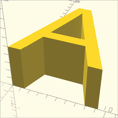
Figure 3-14: Linear extrusion of a 2D shape into a 3D shape
Use all of these parameters to transform a rectangle into the 3D shape drawn in Figure 3-15:
linear_extrude(100, twist=30, slices=25, scale=1/3) {
  square(100, center=true);
}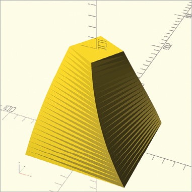
Figure 3-15: Twisting, scaling, and extending a 2D shape into a 3D shape with 25 horizontal slices
The parameters twist, slices, and scale are optional. Although this example shows all three parameters used at once, you can use any variation, such as only scale or only twist.
Extruding Shapes Along a Circle with rotate_extrude
Rather than extruding a 2D shape along a linear path, use the rotate_extrude operation to move the 2D shape along a circular path, which creates a donut-like shape called a torus (Figure 3-16):
rotate_extrude() {
  translate([100, 0]) circle(40);
}
Figure 3-16: The rotate_extrude operation of a 2D circle into a 3D torus
The rotate_extrude operation is a two-step process that first rotates the 2D shape by 90 degrees around the x-axis, then moves the 2D shape in a circle around the z-axis. If you were to cut out a slice of the resulting donut, the shape of that slice would look like the original 2D shape.
When using rotate_extrude, take care to ensure that the shape doesn’t rotate into itself. In the code that draws Figure 3-16, you do this by first translating the shape away from the z-axis so that no parts of the 2D shape are touching the z-axis.
The rotate_extrude operation also takes an optional angle parameter that allows you to specify the angle of rotation. Figure 3-17 demonstrates a circle that has been extruded along a 135-degree rotation around the z-axis.
rotate_extrude(angle=135) {
  translate([100, 0]) circle(40);
}
Figure 3-17: The rotate_extrude with a 135-degree angle parameter
Growing and Shrinking a Shape with offset
Imagine you want to build a fancy cross-shaped cookie cutter. You now know how to create a cross shape by performing a union of two rectangles, and you know how to extrude it by using linear_extrude to make it 3D. But to specify the wall thickness, you need the offset operation, which allows you either to grow or shrink a shape by a specific amount. Use offset to hollow out your cookie cutter by shrinking one cross, and then subtract the small cross from the larger one.
In the following design, pass offset a negative value to shrink your 2D cross (Figure 3-18):
offset(-2) {
  union() {
    square([100, 30], center=true);
    square([30, 100], center=true);
  }
}
Place the code for the 2D shapes to offset in curly brackets following the offset operation. In parentheses, specify the amount (in millimeters) to offset. A positive value will grow a shape, and a negative value will shrink a shape.

Figure 3-18: Shrinking an object by passing offset a negative value
Now you can reuse that code to build the walls of your cross-shaped cookie cutter (Figure 3-19):
linear_extrude(30) {
1 difference() {
  2 union() {
      square([100, 30], center=true);
      square([30, 100], center=true);
    }
  3 offset(-2) {
      square([100, 30], center=true);
      square([30, 100], center=true);
    }
  }
}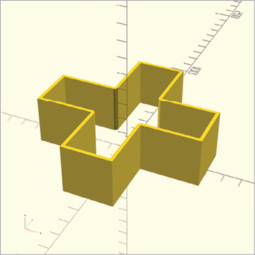
Figure 3-19: Cross-shaped cookie cutter
Define two squares to create the outer cross with a union operation 2. Next, define two more squares to create the inner cross 3, shrink that cross with offset, and then subtract it from the outer cross 1. This leaves you with a hollowed-out cross shape.
Importing 2D Shapes with import
Just as with 3D shapes, you can import 2D shapes from files created in other 2D design programs. OpenSCAD supports importing the .dxf and .svg 2D file formats. These formats are commonly used with popular 2D vector graphic design tools, such as Adobe Illustrator and Inkscape (an open source alternative to Adobe Illustrator). OpenSCAD only supports importing shapes that are closed polygons, containing no “open-ended” sections. Also, make sure you convert all segments in a .dxf file to straight lines.
The syntax of the import command is the same for importing both 2D and 3D shapes. You just need to pass the filename in quotation marks to import, and make sure the file is saved in the same folder/directory as your project. For example, use the following statement to import the drawing in Figure 3-20:
import("drawing.dxf");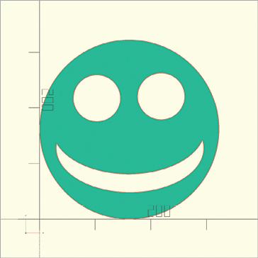
Figure 3-20: An imported .dxf vector graphic
Even though the imported file looks round, it actually consists of many short line segments, similar to the polygons you learned to create earlier in this chapter. Inkscape was used to draw this 2D smiley-face shape. An important final step in the process was to convert all of the line segments in the shape to very small straight lines.
Once you import a 2D shape, it behaves exactly like a built-in shape, and you can transform it and combine it with other shapes. The following statement first imports the smiley face shown in Figure 3-20, then extrudes it into the shape shown in Figure 3-21:
linear_extrude(height=500, scale=3) import("drawing.dxf");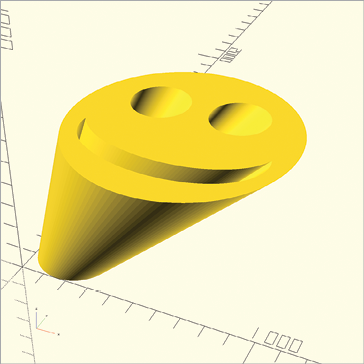
Figure 3-21: An extruded and scaled .dxf vector graphic
Now you have a 3D smiley-face shape that you can 3D-print as a stamp.
Summary
In this chapter, you learned how to design and create 3D shapes based on 2D shapes. You now should be able to create, combine, and transform simple 2D shapes like circles, rectangles, polygons, and text. You can create both internal and external outlines of 2D shapes with the offset operation, import vector graphics, and transform 2D shapes into 3D shapes.
By now you should be able to imagine a wide variety of designs that you could create with OpenSCAD 2D and 3D shapes. Sometimes it’s easier to build a complex 3D design by thinking about its 2D shadow first, and then you can stretch the 2D shadow into 3D.
Here are some important points to remember when working with 2D shapes:
- Rendering a 2D design will display the actual 2D view of the shape, while a Preview window of the design will appear to add a small amount of height along the z-axis.
- 3D shape transformation vectors require three parameters: [x, y, z]; most 2D shape transformation vectors require only two parameters: [x, y].
- 2D rotations need only a single parameter: a number to represent the angle of rotation within the xy-plane.
- The Top view will often give you the best perspective when designing your 2D shapes.
- Extruding 2D shapes and text is necessary in order to combine them with 3D shapes.
- Text strings start and stop with double quotes.
- You can use the
textshape to draw numeric values by converting the value to a string with thestrfunction. - Only fonts that support Unicode can be used to draw emoji, but think of how much fun you could have extruding emoji shapes!
- No part of a 2D shape can cross the z-axis when you use
rotate_extrudeon that shape. - Think of 2D shapes as a “cross section” of the resulting 3D shape from a
rotate_extrudeoperation.