
3Multilevel inverter topologies
Recently, the multilevel inverter technology has emerged as a very important alternative in the area of medium-voltage, high-power applications. As the name indicates, multilevel inverters can produce more than two levels at its output phases. Multilevel inverters also provide benefits such as improved output voltage spectrum. Multilevel inverters offer many benefits for higher-power applications. In particular, these include the ability to synthesize voltage waveform with lower harmonic content than two-level inverters and operation at higher dc voltages using series-connected semiconductor switches. Multilevel inverters with neutral point-clamped (NPC) or diode-clamped technology were introduced in 1980. In the 1990s, new multilevel inverter topologies were introduced. Some important multilevel inverter topologies are NPC multilevel inverter, flying-capacitor multilevel inverter, and cascaded H-bridge multilevel inverter. However, due to simple construction features and other advantages, the NPC topology is widely used.
Higher frequencies are employed in traditional pulse width modulation (PWM) methods because of the undesirable harmonics occurring at higher frequencies, which can be filtered easily and several kilohertz well above the acoustic noise level. However, the traditional PWM methods cause electromagnetic interference (EMI). The rapid change in voltage (dv/dt) is the cause of EMI. A high dv/dt produces common-mode voltages across the windings of motor and leads to damage.
In multilevel inverters, as the switching involves several small voltages, the rapid change in voltage is smaller. Further, switching at the fundamental frequency will also result in the decrease of the number of times these voltage changes occur per fundamental cycle. However, harmonic elimination is the major issue for multilevel inverters. For the following reasons, harmonic elimination in multilevel inverters has been proposed in this book.
i.Harmonics in output voltage create power losses in equipments.
ii.Harmonics are the source of EMI.
iii.Protecting devices such as snubber circuits and filters have to be incorporated in the designed circuits for the elimination of harmonics. Hence, the cost of the circuits increases.
iv.EMI can interfere with control signals used to control power electronic devices and radio signals.
v.Harmonics can create losses in power equipments. Harmonic currents in an induction motor will dissipate power in stator and motor windings.
vi.Harmonics can lower the load power factor.
As mentioned earlier, the use of multilevel inverters results in a better approximation to a sinusoidal waveform because of increased number of dc voltages. These increased number of dc voltages provides the opportunity to eliminate more harmonic contents. The remaining harmonic content can be easily eliminated by less expensive, smaller filters. Because of the large number of dc voltages used in multilevel inverters, several switches are needed to block smaller voltages. Since switch stress is reduced and lower switch ratings are used, if any component fails in the inverter, it will be still usable at reduced power level. In a multilevel inverter, there will be more than one way to generate the desired voltages due to switching redundancies [20]. This will allow for the utilization of smaller and more reliable components. One disadvantage of multilevel inverters is that they require more devices than traditional inverters. Hence, system cost may increase. The probability of system failure increases and control of the switches is also more complicated due to more devices.
There are four kinds of control methods for multilevel inverters. They are traditional PWM control method, selective harmonic elimination method, space vector control method, and SVPWM method. SVPWM is considered a better technique of PWM implementation owing to its associated advantages such as better fundamental output voltage, better harmonic performance, and easier implementation in digital signal processor and microcontrollers.
The main features of multilevel inverter are:
- Ability to reduce the voltage stress on each power device due to the utilization of multiple levels on the dc bus.
- Important when a high-dc side voltage is imposed by an application (e.g. traction systems).
- Even at low switching frequencies, a small distortion in the multilevel inverter ac side waveform can be achieved (with stepped modulation technique).
3.1Diode-clamped multilevel inverter
The diode-clamped multilevel inverter (dcMI) or NPC multilevel inverter is based on the concept of using diodes to limit power devices voltage stress. The structure and basic operating principle consists of series-connected capacitors that divide the dc bus voltage into a set of capacitor voltages.
i.A DCMI with n number of levels typically comprises (N − 1) capacitors on the dc bus.
ii.Voltage across each capacitor is Vdc/(N − 1).
iii.Output phase voltage can assume any voltage level by selecting any of the nodes.
iv.The DCMI is considered a type of multiplexer that attaches the output to one of the available nodes.
v.It consists of main power devices in series with their respective main diodes connected in parallel and clamping diodes.
vi.Main diodes conduct only when most upper or lower node is selected.
vii.Although the main diodes have the same voltage rating as main power devices, much lower current rating is allowable.
viii.In each phase leg, the forward voltage across each main power device is clamped by the connection of diodes between the main power devices and the nodes.
ix.The number of power devices in the ON state for any selection of node is always equal to (N − 1).
The three-phase six-level diode-clamped inverter is shown in Fig. 3.1. Each of the three phases of the inverter shares a common dc bus, which has been subdivided by five capacitors into six levels. The voltage across each capacitor is Vdc and the voltage stress across each switching device is limited to Vdc through the clamping diodes. Table 3.1 lists the output voltage levels possible for one phase of the inverter with the negative dc rail voltage V0 as a reference. State condition 1 means the switch is ON, and 0 means the switch is OFF. Each phase has five complementary switch pairs, such that turning on one of the switches of the pair requires that the other complementary switch be turned off. The complementary switch pairs for phase leg ‘a’ are (Sa1, Sa′1), (Sa2, Sa′2), (Sa3, Sa′3), (Sa4, Sa′4), and (Sa5, Sa′5). Table 3.1 also shows that in a diode-clamped inverter, the switches that are ON for particular phase legs are always adjacent and in series. For a six-level inverter, a set of five switches is ON at any given time.

Fig. 3.1: Three-phase six-level diode-clamped inverter.
Tab. 3.1: Switching states of the six-level diode-clamped inverter.

i.For three-phase dcMI, the capacitors need to filter only the high-order harmonics of the clamping diodes currents, low-order components intrinsically cancel each other.
ii.For dcMI employing step modulation strategy, if n is sufficiently high, filters may not be required at all due to the significantly low harmonic content.
iii.If each clamping diode has same voltage rating as power devices, for n-level dcMI.
iv.Number of clamping diodes/ phase = (N − 1) × (N − 2).
v.Each power device blocks only a capacitor voltage.
i.All of the phases share a common dc bus, which minimizes the capacitance requirements of the converter.
ii.The capacitors can be precharged as a group.
iii.Efficiency is high for fundamental frequency switching.
i.Real power flow is difficult for a single inverter because the intermediate dc levels will tend to overcharge or discharge without precise monitoring and control.
ii.The number of clamping diodes required is quadratically related to the number of levels, which can be cumbersome for units with a high number of levels.
3.2Flying capacitor multilevel inverter
Flying capacitor multilevel inverter is capable of solving capacitor voltage unbalance problem and excessive diode count requirement in diode capacitor multilevel inverter and it is also known as flying capacitor multilevel inverter (capacitors are arranged to float with respect to earth). The structure and basic operating principle of flying capacitor multilevel inverter are the following:
i.Employs separate capacitors precharged to
ii.The size of voltage increment between two capacitors defines the size of voltage steps in flying capacitor multilevel inverter output voltage waveform.
iii.N-level flying capacitor multilevel inverter has n-level output phase voltage and (2N − 1)-level output line voltage.
iv.The output voltage is produced by switching the right combinations of power devices to allow adding or subtracting of capacitor voltages.
For example, the three-phase six-level flying capacitor multilevel inverter is shown in Fig. 3.2. The structure of this inverter is similar to that of the diode-clamped inverter except that instead of using clamping diodes, the inverter uses capacitors in their place. This topology has a ladder structure of dc side capacitors, where the voltage on each capacitor differs from that of the next capacitor.
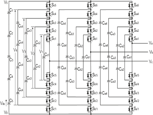
Fig. 3.2: Three-phase six-level flying capacitor inverter.
i.With step modulation strategy, with sufficiently high n, harmonic content can be low enough to avoid the need for filters.
ii.Advantage of inner voltage-level redundancies: allows preferential charging or discharging of individual capacitors and facilitates manipulation of capacitor voltages so that their proper values are maintained.
iii.Active and reactive power flow can be controlled.
iv.Additional circuit required for initial charging of capacitors.
i.Phase redundancies are available for balancing the voltage levels of the capacitors.
ii.Real and reactive power flow can be controlled.
iii.The large number of capacitors enables the inverter to ride through short-duration outages and deep voltage sags.
i.Control in tracking the voltage levels for all of the capacitors is complicated. Also, precharging all the capacitors to the same voltage level and startup are complex.
ii.Switching utilization and efficiency are poor for real power transmission. The large numbers of capacitors are both more expensive and bulky than clamping diodes in multilevel diode-clamped converters. Packaging is also more difficult in inverters with a high number of levels.
3.3Cascade H-bridge multilevel inverter
This refers to modular structured multilevel inverter (MSMI) or series-connected H-bridge inverters. The structure and basic operating principle of cascade H-bridge multilevel inverter consists of (N − 1)/2 or h number of single-phase H-bridge inverters (MSMI modules). The MSMI output phase voltage is
A single-phase structure of an m-level cascaded inverter is illustrated in Fig. 3.3. Each separate dc source (SdcS) is connected to a single-phase full-bridge or H-bridge inverter. Each inverter level can generate three different voltage outputs +Vdc, 0, and –Vdc by connecting the dc source to the ac output by different combinations of the four switches S1, S2, S3, and S4. To obtain +Vdc, switches S1 and S4 are turned ON, whereas −Vdc can be obtained by turning ON switches S2 and S3. By turning ON S1 and S2 or S3 and S 4, the output voltage is 0. The ac outputs of each of the different full-bridge inverter levels are connected in series such that the synthesized voltage waveform is the sum of the inverter outputs. The number of output-phase voltage levels m in a cascade inverter is defined by m = 2s + 1, where s is the number of separate dc sources.

Fig. 3.3: Single-phase structure of cascaded H-bridge inverter.
i.The number of possible output voltage levels is more than twice the number of dc sources (m = 2s + 1).
ii.The series of H-bridges makes for modularized layout and packaging. This will enable the manufacturing process to be done more quickly and cheaply.
i.Separate dc sources are required for each of the H-bridges. This will limit its application to products that already have multiple SdcSs readily available.
ii.As the level of the output voltage produced increases, the switch count will also increase.
In this chapter, the state of the art of different multilevel inverters, which have potential applications in the area of medium-voltage and high-power applications, has been discussed. The fundamental multilevel inverter topology, principle of operation, and its features with advantages and disadvantages have been explained in detail for the three basic topologies. The limitations of the two-level inverters in terms of switching frequency, switching losses, and dv/dt issues have been resolved with multilevel inverters. A procedure for calculating the required ratings for the active switches, clamping diodes, and dc-link capacitors for N-level has been described. The main objective of this chapter was to provide a general idea to readers interested in multilevel inverters and the pros and cons of their real-time implementation.