
Chapter 10
Bootstrapping Embedded
Capitalists are no more capable of self-sacrifice than a man is capable of lifting himself up by his own bootstraps.
—Vladimir Lenin
Bootstrapping to a computing device is the act of bringing the system up without any manual entry. It may be an antiquated term, but most operating systems are not native software on Intel® architecture (which start at 0xFFFFFFF0h) and cannot bootstrap themselves. BIOS and boot loaders have one main task to do—the bare minimum required to initialize enough hardware, and then get out of the way for the more robust operating system to take over. In some cases, the BIOS or bootloader should query the user or system for preferences, perform scans for bootable partitions, enumerate expansion buses, or run diagnostics in the case of a unit failure. These are usages where the OS seems unreachable or something seems incorrect with the hardware, but people typically just want to get to the OS to run their application or answer their email or phone or play the latest YouTube† video from the Internet; they do not want to wait for a BIOS to boot.
As a system designer, you can look at the Apple iPad† for the latest industry benchmark in bootstrapping. As with most embedded computing devices, it doesn’t boot, it turns on. While the comparison may not be fair in that the iPad isn’t actually booting most of the time, it is just coming out of a lower power state; the end user doesn’t care. Consumers will be expecting that level of responsiveness going forward. One could easily argue that mobile phones really boot once, then have a short turn on/off time similar to that of a PC’s standby sleep mode. But until the likes of Windows† and Linux decide to bootstrap themselves natively from a true OFF without the need for a BIOS or bootloader, we as system developers will have to adapt tried and true BIST and POST to a new world order, in innovative ways, or have our products stay on the shelf at the store and then get moved directly to a museum, still in the original packaging. We need to understand how to optimize the boot times for performance; this is especially true for the embedded-market space, where the system needs to effectively turn on, not boot.
But first, we need to put things in perspective.
Optimization Using BIOS and Bootloaders
Some of the typical optimizations that can be applied include:
–Platform policy rethink
–Turn off debugging
–Decrease flash size
–Cache as RAM pre-memory during PEI phase
–Intel SpeedStep® technology enabled early
–BDS optimization (boot devices)
–Platform memory speed
–Remove PS/2 keyboard/mouse
–Remove BIOS setup
–Remove video option ROM
–Remove BIOS USB functional support
–Eliminate unnecessary data table creation
–Booting to UEFI operating systems
–Using UEFI drivers instead of option ROMS
–Using UEFI services
–Removed setup menu
–Using a solid-state drive versus hard-disk drive to eliminate spin-up time and accelerate OS loading
This is not an all-inclusive list. Let’s look at each of them individually that can be applied per design and then look at a better architectural method.
Platform Policy (What Is It and Why Is It Here?)
One of the first considerations when looking at a system BIOS and the corresponding requirements is whether you can limit the number of variables associated with what the user can do with or to the system.
You’re pirates. Hang the code, and hang the rules. They’re more like guidelines anyway.
—Elizabeth to crew of the Black Pearl in Pirates of the Caribbean
For instance, it might be reasonable to presume that in a platform with no add-in slots, a user will not be able to boot from a RAID controller, since there is no integrated component for RAID in the chipset or down on the board. The user cannot expect it to be initialized.
This is where a designer enters the “platform policy zone.” These policies are dynamic; when you truly understand the “what” and the “why,” you can institute changes. You can question everything and not stand on tradition. Even though a platform may not expose an add-in slot, the platform might expose a USB connection. A conscious decision needs to be made for how and when these components are used. We need to make informed decisions in these cases.
In some cases, it is determining what you don’t need to do in the BIOS space versus the operating system space. This can be more important for boot time reductions than what you need to do during the boot flow. Example: If the OS kernel or drivers are going to repeat the bus/device enumeration of the entire PCI subsystem, for SATA, or for USB hubs/devices, then you only need to do what you must to get the OS loaded and executing and skip the rest. Too often, the standard PC BIOS handles many inane corner cases that can be found in one or two devices on the market for the sake of ultimate backward compatibility, all the way back to DOS. A standard PC BIOS fills out every line of every legacy data table in memory regardless of whether the OS or application needs the data. It has been considered a real added value that someone in the universe who buys this motherboard may install some legacy application, and we may want to make sure it is a very robust solution. Some devices will need to comprehend all the baggage because there will continue to be that part of the market. In all cases for fast boot, however, developers are encouraged to reduce, reduce, reduce.
For instance, since a user can connect anything from a record player to a RAID chassis via USB, users might think they can boot from a USB-connected device. Though this is physically possible, it is within the purview of the platform design to enable or disable this feature.
A good general performance optimization statement would be: If you can put off doing something in BIOS that the OS can do, then put it off! Look at the whole boot chain between bootloader, potential second-stage agents, the OS, and shutdown. You need to be examining the concept of moving the finish line closer to the ball, understanding there are tradeoffs between firmware and OS initialization. This is advanced because you need to have control and insight into each of the phases of the boot flows for a platform.
Ask the second part of the question: why is it here? If it is for a keyboard or mouse input during runtime, or to a USB stick to copy files locally to and from the system during runtime, then we probably will not need to fully enumerate the bus during boot time or incorporate a full USB firmware stack.
In Example 1 below, the decision was made to not support booting from USB media and to not support the user interrupting the boot process via keyboard/mouse. This means that during the DXE/BDS phase, the BIOS can avoid initializing the USB infrastructure to get keystrokes and save 0.5 seconds of boot time.
It should be noted that PCI resources were assigned to the USB controllers on the platform, but by eliminating BIOS USB enumeration we saved 0.5 seconds. Upon launching the platform OS, the OS still could interact with plugged- in USB devices without a problem because the OS drivers will normally reset the USB controllers and re-enumerate the USB bus/devices to suit its own needs. No wonder the OS takes so long to boot … what else may the OS reinitialize and re-enumerate during a cold or warm boot?
Platform policy ultimately affects how an engineer responds to the remaining questions.
Case Study Summaries
We have experimented with boot times and presented case studies in the Intel Developer’s Forum (IDF) in the past. Here are two examples.
Example 1
The overall performance numbers used in this example are measured in microseconds and the total boot time is described in seconds. Total boot time is measured as the time between the CPU coming out of reset and the handoff to the next boot agent.
The hardware used was:
–1.8 Ghz Intel® Atom™–based netbook design
–1 GB DDR2 memory
–2 MB flash
–Western Digital 80GB Scorpio Blue 5400 RPM drive
–Intel® Solid State Drive X25-E
It should also be noted that this proof of concept was intended to emulate real-world expectations of a system BIOS, meaning nothing was done to achieve results that could not reasonably be expected in a mass-market product design. The steps that were taken for this effort should be easily portable to other designs and should largely be codebase-independent.
Table 10.1 lists the performance numbers achieved while maintaining broad market requirements.
Table 10.1: Performance Measurement Results – Before/After

Example 2
Measurements were taken starting from a configuration based on the original Intel Atom processor. The performance numbers achieved are listed in Table 10.2.
–Intel Atom Processor Z530/Z10 (C0 stepping)
–Intel® SCH US15W chipset (D1 stepping)
–512 MB DDR2 memory at 400 MHz
–2 MB flash
Table 10.2: Performance Measurements for Example 2

While a different combination of techniques was used between these two teams in these examples, it should be noted that the second trial was more focused on the embedded market scenarios and striving to simply reduce boot times as much as possible without regard to the broad market. The difference, while noticeable, would not be that great.
Example 1 Details
Some of the details are listed in Table 10.3.
| Change | Boot Time (in seconds) | Incremental boot time improvement (in seconds) |
| Initial configuration | 9.65 | — |
| Eliminate SMBIOS tables | 9.25 | 0.4 |
| Booting to UEFI target | 8.75 | 0.5 |
| Using UEFI drivers instead of option ROMs | 5.75 | 3.0 |
| Using an SSD versus HDD to eliminate spin-up time | 3.65 | 2.1 |
| Using UEFI services | 3.40 | 0.25 |
| Removed setup menu | 1.99 | 1.41 |
Admittedly, broad marketing requirements are not the first thing that comes to mind when a developer sits down to optimize a firmware for performance; however, the reality is that marketing requirements form the practical limits for how the technical solution can be adjusted.
Answering some basic questions can help you make decisions that will set outer bounds and define the performance characteristics of the system. Since this section details the engineering responses to marketing requirements, it does not provide a vast array of code optimization tricks. Unless the code has a serious set of implementation bugs, the majority of boot speed improvements can be achieved from the following guidelines. There are codebase-independent tricks spelled out.
What Are the Design Goals?
How does the user need to use the platform? Is it a closed-box system? Is it more of a traditional desktop PC? Is it a server-based system with some unique add-ons? How the platform is thought of will ultimately affect what users expect. Making conscious design choices to either enable or limit some of these expectations is where the platform policies can greatly affect the resulting performance characteristics.
What Are the Supported Target Operating Systems?
Understanding the requirements of a particular platform-supported OS will greatly affect what optimization paths can be taken in the BIOS. Since many “open” platforms have a wide variety of operating systems that they support, this limits some of the choices available. In the case of the proof-of-concept platform, there were only two main operating systems that were required to be supported. This enabled the author to make a few choices that allowed the codebase to save roughly 400 ms of boot time by avoiding the reading of some of the DIMM SPD data for creating certain SMBIOS records since they weren’t used by the target operating systems.
Changes in the BIOS codebase that avoided the unnecessary creation of certain tables saved roughly 400 ms in the boot time.
Do We Have to Support Legacy Operating Systems?
Are the target operating systems UEFI-compliant or not? If all the OS targets are UEFI-compliant, then the platform can save roughly 0.5 second in initialization of the video option ROM. In this case, there were two operating systems that needed to be booted on the same motherboard. We had conflicting requirements where one was UEFI-compliant and one was not. There are a variety of tricks that could have been achieved by the platform BIOS when booting the UEFI-compliant OS but for purposes of keeping fair measurement numbers, the overall boot speed numbers reflect the overhead of supporting legacy operating systems as well (the compatibility segment module [CSM] was executed).
Do We Have to Support Legacy Option ROMs?
Whether or not to launch a legacy option ROM depends on several possible variables:
–Does the motherboard have any devices built-in that have a legacy option ROM?
–Does the platform support adding a device that requires the launch of a legacy option ROM?
–If any of the first two are true, does the platform need to initialize the device associated with that option ROM?
Trick: To save an additional 0.5 second or more of boot time when booting a UEFI-compliant OS, the BDS could analyze the target BOOT#### variable to determine if the target was associated with an OS loader—thus it is a UEFI target. The platform in this case at least has the option to avoid some of the overhead associated with the legacy compatibility support infrastructure.
One reason why launching legacy option ROMs is fraught with peril for boot performance is that there are no rules associated with what a legacy option
ROM will do while it has control of the system. In some cases, the option ROM may be rather innocuous regarding boot performance, but in other instances that is not the case. For example, the legacy option ROM could attempt to interact with the user during launch. This normally involves advertising a hot key or two for the user to press, which would delay the BIOS in finishing its job for however long the option ROM pauses waiting for a keystroke.
Trick: For this particular situation, we avoided launching all the drivers in a particular BIOS and instead opted to launch only the drivers necessary for reaching the boot target itself. Since the device we were booting from was a SATA device for which the BIOS had a native UEFI driver, there was no need to launch an option ROM. This action alone saved approximately three seconds on the platform. More details associated with this trick and others are in the Additional Details section.
Are We Required to Display an OEM Splash Screen?
This is a crucial element for many platforms, especially from a marketing point of view. The display of the splash screen itself typically does not take that much time. Usually, initializing the video device to enable such a display takes a sizable amount of time. On the proof-of-concept platform, it would typically take 300 ms. An important question is how long does marketing want the logo to be displayed? The answer to this question will focus on what is most important for the OEM delivering the platform. Sometimes speed is paramount (as it was with this proof of concept), and the splash screen can be eliminated completely. Other times, the display of the logo is deemed much more important and all things stop while the logo is displayed. An engineer’s hands are usually tied by the decisions of the marketing infrastructure.
One could leverage the UEFI event services to take advantage of the marketing-driven delay to accomplish other things, which effectively makes some of the initialization parallel.
What Type of Boot Media Is Supported?
In the proof-of-concept platform description, one element was a bit unusual. There was a performance and a standard configuration associated with the drive attached to the system. Though it may not be obvious, the choice of boot media can be a significant element in the boot time when you consider that some drives require 1 to 5 seconds (or much more) to spin up. The characteristics of the boot media are very important since, regardless of whatever else you might do to optimize the boot process, the platform still has to read from the boot media, and there are some inherent tasks associated with doing that. Spin-up delays are among those tasks that are unavoidable in today’s rotating magnetic media.
For the proof of concept, the boot media of choice was one that incurs no spin-up penalty; thus, a solid-state drive (SSD) was chosen. This saved about two seconds from the boot time.
What Is the BIOS Recovery/Update Strategy?
How a platform handles a BIOS update or recovery can affect the performance of a platform. Since this task can be accomplished in many ways, this may inevitably be one of those mechanisms with lots of platform variability. There are a few very common cases on how a BIOS update is achieved from a user’s perspective:
- A user executes an OS application, which he or she likely downloaded from the OEM’s Web site. This will eventually cause the machine to reboot.
- A user downloads a special file from an OEM’s website and puts it on a USB dongle and reboots the platform with the USB dongle connected.
- A user receives or creates a CD or flash drive with a special file and reboots the platform to launch the BIOS update utility contained within that special file.
These user scenarios usually resolve into the BIOS, during the initialization caused by the reboot, reading the update/recovery file from a particular location. Where that update/recovery file is stored and when it is processed is really what affects performance.
When Processing Things Early
Frequently during recovery, one cannot presume that the target OS is working. For a reasonable platform design, someone would need to design a means by which to update or recover the BIOS without the assistance of the OS. This would lead to user scenarios 2 or 3 listed above.
The question engineers should ask themselves is, how do you notify the BIOS that the platform is in recovery mode? Depending on what the platform policy prescribes, this method can vary greatly. One option is to always probe a given set of possible data repositories (such as USB media, a CD, or maybe even the network) for recovery content. The act of always probing is typically a time-consuming effort and not conducive to quick boot times.
There is definitely the option of having a platform-specific action that is easy and quick to probe that “turns on” the recovery mode. How to turn on the recovery mode (if such a concept exists for the platform) is very specific to the platform. Examples of this are holding down a particular key (maybe associated with a GPIO), flipping a switch (equivalent of moving a jumper) that can be probed, and so on. These methods are highly preferable since they allow a platform to run without much burden (no extensive probing for update/recovery.)
Is There a Need for Pre-OS User Interaction?
Normally the overall goal is to boot the target OS as quickly as possible and the only expected user interaction is with the OS. That being said, the main reason people today interact with the BIOS is to launch the BIOS setup. Admittedly, some settings within this environment are unique and cannot be properly configured outside of the BIOS. However, at least one major OEM (if not more) has chosen to ship millions of UEFI-based units without exposing what is considered a BIOS setup. It might be reasonable to presume for some platforms that the established factory default settings are sufficient and require no user adjustments. Most OEMs do not go this route. However, it is certainly possible for an OEM to expose applets within the OS to provide some of the configurability that would have otherwise been exposed in the pre-OS phase.
With the advent of UEFI 2.1 (and more specifically the Human Interface Infrastructure [HII] content in that specification), it became possible for configuration data in the BIOS to be exposed to the OS. In this way, many of the BIOS settings can have methods exposed and configured in what are not traditional (pre-OS) ways.
If it is deemed unnecessary to interact with the BIOS, there is very little reason (except as noted in prior sections) for the BIOS to probe for a hot key. This only takes time from a platform boot without being a useful feature of the platform.
A Note of Caution
When trying to optimize the settings for hardware and OS interaction features, such as power management flows, which are enabled and controlled via a combination of hardware and software, it is important not to oversimplify the firmware setting. Often, the tradeoffs and ramifications are going to be beyond the simple boot flow to get to the OS. For these settings, extreme care should be taken to understand the downstream usage model and workloads that are going to be exercising these features. Experiment with these settings, but do not be surprised if the resulting data does not support your original hypothesis.
Additional Details
When it comes time to address some codebase issues, the marketing requirements clearly define the problem space an engineer has to design around. With that information, there are several methods that can help that are fairly typical of a UEFI-based platform. This is not intended to indicate these are the only methods, but they are the ones most any UEFI codebase can exercise.
Adjusting the BIOS to Avoid Unnecessary Drivers
It is useful to go into and understand the details of how we avoided executing some of the extra drivers in our platform. It is also useful to reference the appropriate sections in the UEFI specification to better understand some of the underlying parts that, for conciseness, cannot be covered in this book.
The BDS phase of operations is where various decisions are made regarding what gets launched and what platform policy is enacted. That being said, this is the code (regardless of which UEFI codebase you use) that will frequently get the most attention in the optimizations. If we refer again to the boot times for our proof of concept, it should be noted that the BDS phase was where the majority of time was reduced. Most of the reduction had to do with optimizations as well as some of the design choices that were made and the phase of initialization where that activity often takes place.
At its simplest, the BDS phase is the means by which the BIOS completes any required hardware initialization so that it can launch the boot target. At its most complex, you can add a series of platform-specific, extensive, value-added hardware initialization not required for launching the boot target.
What Is a Boot Target?
The boot target is defined by something known as an EFI device path (see the UEFI specification). This device path is a binary description of where the required boot target is physically located. This gives the BIOS sufficient information to understand what components of the platform need to be initialized to launch the boot target.
Below is an example of just such a boot target:


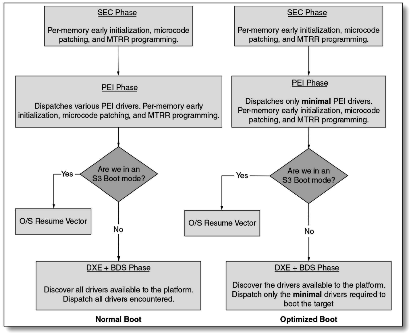
Steps Taken in a Normal and Optimized Boot
Figure 10.1 indicates that between the normal boot and an optimized boot, there are no design differences from a high level (UEFI) architecture point of view. So optimizing a platform’s boot performance does not mean that one has to violate any of the EFI platform initialization design specifications.
It does mean that you have to go through each module and ask the big questions: Can I eliminate it entirely? Can I reduce the corner cases? Are there going to be variables in this equation or bit field? (See Figure 10.2.)
Loading a Boot Target
The logic associated with the BDS optimization focuses solely on what is the minimal behavior associated with initializing the platform and launching the OS loader. When customizing the platform BDS, you can avoid calling routines that attempt to connect all drivers to all devices recursively, such as BdsConnectAll(), and instead connect only the devices directly associated with the boot target. Figure 10.3 shows an example of that logic.

Organize the Flash Effectively
In a BIOS that complies with the PI specification, there is a flash component concept known as a firmware volume (FV). This is typically an accumulation of BIOS drivers. It would be reasonably expected that these FVs are organized into several logical collections that may or may not be associated with their phase of operations or functions. There are two major actions the core initiates that are associated with drivers. The first is when a driver is dispatched (loaded into memory from flash), and the second one is when a driver is connected to a device. Platform policy could dictate that the DXE core avoids finding unnecessary drivers. For instance, if the USB device boot is not needed, the USB-related drivers could be segregated to a specific FV, and material associated with that FV would not be dispatched.
Minimize the Files Needed
Since one of the slowest I/O resources in a platform is normally the flash part on which the BIOS is stored, it is prudent to minimize the amount of space a BIOS occupies. The less space it occupies, the shorter the time for routines within the BIOS to read content into faster areas of the platform (such as memory). This can be done by minimizing the drivers required by the platform, and pruning can typically be accomplished by a proper study of the marketing requirements.
Example 2 Details
Table 10.4 depicts the results of the boot time investigation, followed by in- depth discussion of each change.
| Change | Boot time (in seconds) | Incremental boot time improvement (in seconds) |
| Initial configuration | 11.66 | - |
| Turn off debugging | 8.39 | 3.27 |
| Decrease flash size | 8.18 | 0.21 |
| Caching of PEI phase | 7.91 | 0.27 |
| Intel SpeedStep® technology enabled early | 7.82 | 0.09 |
| BDS optimization (boot devices) | 7.53 | 0.29 |
| Platform memory speed | 7.43 | 0.10 |
| Remove PS/2 keyboard/mouse | 7.36 | 0.07 |
| Remove BIOS setup | 5.43 | 1.93 |
| Remove video option ROM | 3.33 | 2.10 |
| Remove BIOS USB support | 1.65 | 1.68 |
Turn Off Debugging
Turning off debugging removes the serial debugging information and turns on C Compiler optimizations. Because framework BIOS is almost entirely written in C (unlike earlier BIOS versions, which were written in assembly language), enabling compiler optimizations is particularly useful.
EFI BIOS makes extensive use of spewing debugging information over a serial port to aid development and debug of the BIOS. While this debugging information is valuable in a development environment, it can be eliminated in a production environment. In addition to the boot time improvements realized, there are also IP considerations to shipping a BIOS developed in a higher-level language that has debugging information enabled.
Likewise, compiler optimizations must be disabled when it is desired to perform source level debug of the C language BIOS code. However, in production this can be eliminated.
Decrease Flash Size
This step represents modifying the BIOS build process to use a 1 MB flash part instead of the original 2 MB flash part. This includes decreasing the number of flash blocks used in the board process. The framework BIOS uses a flash file system to store PEI and DXE modules as well as other entities. Decreasing the number of blocks in this file system improves the access time each time a module is accessed.
Caching of PEI Phase
Many of the PEI modules in framework BIOS must be executed prior to platform memory being initialized. Once memory is initialized, the remaining portions of the BIOS are copied to system memory and executed out of memory. Because the framework BIOS uses cache-as-RAM (CAR) for pre-memory storage and stack, it runs all the PEI modules in place directly from the flash part without caching. It is possible, however, on the Intel® Atom™ processor to simultaneously enable CAR plus one 64 KB region of normally cached address space. The BIOS must be arranged in such a way to take full advantage of this one prememory cacheable region. This means having a separate flash file system used exclusively by the PEI modules that are run prior to memory initialization and placing that file system in the region that will be cached. By employing this technique to cache the portion of the flash part that includes the PEI modules executing prior to initialization of memory, performance is increased. For this effort, the 64 KB region was unable to cover all the PEI modules. Through further reduction in size of PEI, more improvement is possible.
Intel SpeedStep® Technology Enabled Early
Intel SpeedStep® technology is a power savings technology used to limit the processor speed based on current software demand on the system. When the system is in heavy use, the processor is run at full speed. At idle and near idle, the system is run at slower speed “steps.”
The BIOS role in initialization of Intel SpeedStep technology includes detection of Intel SpeedStep technology capabilities, initialization of the processor speed for all processor threads, and advertisement of Intel SpeedStep capabilities for the operating system. The above “initialization of all processor threads” is typically to the “power on” speed, which is normally equal to the lowest supported speed. This is to ensure increased stability during the boot process. The operating system will then enable the faster steps.
To increase boot speed, the BIOS, instead of enabling the “power on” feature of Intel SpeedStep® technology, can enable the highest speed setting. This not only increases the speed of the processor during a BIOS post, but also increases the speed of loading the operating system.
BDS Phase Optimization
The framework BIOS BDS phase normally looks for potential boot devices from hard drives, CD-ROM drives, floppy drives, and network. On the investigation platform, the requirements were for boot from hard disk. This optimization removes the BDS checks for boot devices on CD-ROM, floppy, and network since they are not supported on this platform. If the operating system is being loaded from flash instead of hard disk, the hard disk would be replaced with an optimized flash boot.
Platform Memory Speed
Noticeable boot time improvement was realized by using the highest memory speed supported on the platform. On platforms featuring the Intel Atom processor, this is determined by a set of jumpers on the board. On other platforms, this may be a setting in BIOS setup.
Remove PS/2 Keyboard/Mouse
Initialization of the PS/2 keyboard and mouse in the BIOS takes a considerable amount of time due to the specification of these devices. This eliminates the possibility of interacting with the BIOS during the BIOS post and operating system loader. If BIOS setup has been removed as discussed below, user input is not needed during the BIOS. On a fielded embedded device, keyboard and mouse are typically not needed and therefore do not need to be initialized. During device development and debug this feature might be better left on until the device is operational.
Remove BIOS Setup
During the boot process, the BIOS provides an opportunity for the user to hit a hot key that terminates the boot process and instead displays a menu used to modify various platform settings. This includes settings such as boot order, disabling various processor or chipset features, and modifying media parameters. On an embedded device, BIOS setup (and any similar settings provided by an operating system loader) is more of a liability since it gives the end user access to BIOS features that are potentially untested on the device. It is better to have a set of setup options that may be chosen at BIOS build time. Removal of the BIOS setup also saves significant BIOS post time.
Remove Video Option ROM
The video option ROM on platforms featuring the Intel Atom processor and many other newer platforms is quite slow due to the many different video interfaces that must be supported and the display detection algorithms that must be employed. Replacement of a highly optimized DXE video driver in place of the video option ROM saves significant boot time. The speed of this optimized DXE video driver is highly dependent on the exact display chosen and video features required by the platform prior to installation of the operating system graphics driver. On the investigation platform, a fixed splash screen was displayed. It was unchanged during the boot process until the operating system graphics driver initialized the display. To achieve this, the capability to display text was removed from the DXE graphics driver. As a result, none of the normal BIOS or operating system initialization messages is displayed. This yields additional performance and a cleaner boot appearance.
Remove BIOS USB Support
Since USB-boot and a USB input device like a keyboard/mouse were not requirements on the investigation platform, initialization of USB was completely removed from boot flow. USB is still available from the operating system once the driver is loaded but not during the BIOS or OS loader.
Divide Long Lead Pieces into Functional Blocks and Distribute Across the Boot Flow
While BIOS today is not multithreaded, there are some things that can still be done in parallel. Not waiting around for long timeouts or scans and breaking up the activities between multiple functions across the boot flow are two good ways to eliminate idle delay times. Example: command the hard drives to spin up early in the boot flow. It should be noted that even solid-state drives have a firmware readiness time minimum before data can be retrieved. This can be mitigated by warming up the drives. Similarly, newer LCD displays may have a minimum time required to turn on the backlight, or perform a costly 900 ms reset on each power cycle.
Keeping the CPU fully occupied as well as any DMA engine during OS loading or BIOS shadow is another method of running some of the longer lead activity in parallel. One can start to load the data from the storage to memory at the same time you are executing other items. Bottom line: don’t stand around whistling while you wait for hardware or timeouts when you can be doing real work.
Summary
This chapter covers several potential optimizations that can be implemented on a broad array of embedded platforms, depending on the policy decisions and requirements of the platform.
It is important to note that some latent firmware bugs were found that only became apparent when optimizations were enabled. For this reason, rigorous validation is recommended after enabling these and optimizations.
In creating new paths for optimizations, it is important to get as much data as you can from experts on a particular component or subsystem. Often the details will not be written down in specifications.
None of us got where we are solely by pulling ourselves up by our bootstraps. We got here because somebody—a parent, a teacher, an Ivy League crony or a few nuns—bent down and helped us pick up our boots.
—Thurgood Marshall