
Perform the following steps to create a small Rover-Pi robot:
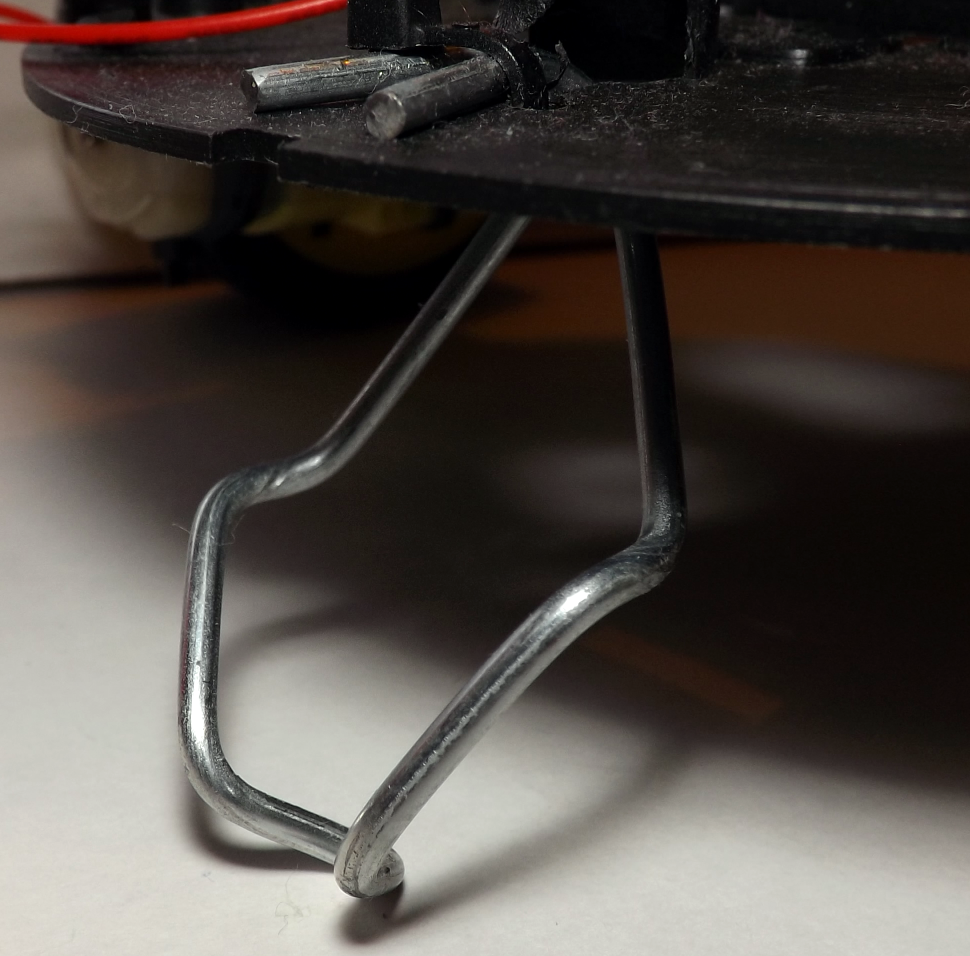
- At the front of the chassis, you will need to mount the skid by bending the
paperclip/wire into a V shape. Attach the paperclip/wire to the front of the chassis by drilling small holes on either side, threading cable ties through the holes around the wire, and pulling tightly to secure. The fitted wire skid should look similar to the one shown in the following photo:
- Before you mount the wheels, you need to work out the approximate center of gravity of the chassis (do this with the batteries fitted in the chassis, as they will affect the balance). Get a feel of where the center is by trying to balance the unit on two fingers on either side and finding out how far forward or backward the chassis tilts. For my unit, this was about 1 cm (approximately one-third of an inch) back from the center. You should aim to place the wheel axles slightly behind this so that the rover will rest slightly forward on the skid. Mark the location of the wheels on the chassis.
- Drill three holes on each side to mount the wheels using the cable ties. If the cable ties aren't long enough, you can join two together by pulling the end of one through the end of the other (only pull through far enough for the tie to grip so that it extends the tie). The following diagram shows how you can use the cable ties:

- Next, test the motors by inserting the batteries into the unit; then, disconnect the wires that originally connected to the bulb, and touch them to the motor contacts. Determine which connection on the motor should be positive and which should be negative for the motor to move the robot forward (the top of the wheel should move forward when the robot is facing forwards). Connect red and black wires to the motor (on mine, black equals negative at the top of the motor, and red equals positive at the bottom), ensuring that the wires are long enough to reach anywhere on the chassis (around 14 cm, that is, approximately 5.5 inches, is enough for the nightlight).
The Rover-Pi robot components should be wired up as shown in the following diagram:

To make the connections, perform the following steps:
- Connect the black wires of the motors to the OUT 1 (left) and OUT 2 (right) output of the Darlington module, and connect the red wires to the last pin (the COM connection).
- Next, connect the battery wires to the GND/V- and V+ connections at the bottom of the module.
- Finally, connect the GND from the GPIO connector (Pin 6) to the same GND connection.
- Test the motor control by connecting 3.3V (GPIO Pin 1) to IN1 or IN2, to simulate a GPIO output. When you're happy, connect GPIO Pin 16 to IN1 (for left) and GPIO Pin 18 to IN2 (for right).
The wiring should now match the details given in the following table:
|
Raspberry Pi GPIO |
Darlington module |
|
Pin 16: Left |
IN1 |
|
Pin 18: Right |
IN2 |
|
Pin 6: GND |
GND/V- (marked with -) |
|
Motor 4 x AA battery Darlington module |
|
|
Positive side of battery |
V+ (marked with +) |
|
Negative side of battery |
GND/V- (marked with -) |
|
Motors |
|
|
Left motor: black wire |
OUT 1 (top pin in white socket) |
|
Right motor: black wire |
OUT 2 (second pin in white socket) |
|
Both motors: red wires |
COM (last pin in white socket) |
Use the following rover_drivefwd.py script to test the control:
#!/usr/bin/env python3
#rover_drivefwd.py
#HARDWARE SETUP
# GPIO
# 2[==X====LR====]26[=======]40
# 1[=============]25[=======]39
import time
import wiringpi2
ON=1;OFF=0
IN=0;OUT=1
STEP=0.5
PINS=[16,18] # PINS=[L-motor,R-motor]
FWD=[ON,ON]
RIGHT=[ON,OFF]
LEFT=[OFF,ON]
DEBUG=True

class motor:
  # Constructor
  def __init__(self,pins=PINS,steptime=STEP):
    self.pins = pins
    self.steptime=steptime
    self.GPIOsetup()

  def GPIOsetup(self):
    wiringpi2.wiringPiSetupPhys()
    for gpio in self.pins:
      wiringpi2.pinMode(gpio,OUT)

  def off(self):
    for gpio in self.pins:
      wiringpi2.digitalWrite(gpio,OFF)

  def drive(self,drive,step=STEP):
    for idx,gpio in enumerate(self.pins):
      wiringpi2.digitalWrite(gpio,drive[idx])
      if(DEBUG):print("%s:%s"%(gpio,drive[idx]))
    time.sleep(step)
    self.off()

  def cmd(self,char,step=STEP):
    if char == 'f':
      self.drive(FWD,step)
    elif char == 'r':
      self.drive(RIGHT,step)
    elif char == 'l':
      self.drive(LEFT,step)
    elif char == '#':
      time.sleep(step)

def main():
  import os
  if "CMD" in os.environ:
    CMD=os.environ["CMD"]
    INPUT=False
    print("CMD="+CMD)
  else:
    INPUT=True
  roverPi=motor()
  if INPUT:
    print("Enter CMDs [f,r,l,#]:")
    CMD=input()
  for idx,char in enumerate(CMD.lower()):
    if(DEBUG):print("Step %s of %s: %s"%(idx+1,len(CMD),char))
    roverPi.cmd(char)

if __name__=='__main__':
  try:
    main()
  finally:
    print ("Finish")
#End
Run the previous code using the following command:
sudo python3 rover_drivefwd.py
The script will prompt you with the following message:
Enter CMDs [f,r,l,#]:
You can enter a series of commands to follow; for example:
ffrr#ff#llff
The preceding command will instruct the Rover-Pi robot to perform a series of movements: forward (f), right (r), pause (#), and left (l).