
You may have noticed that the matrix class also returns a byte when we send the data on the MOSI line. This is the data output from the MAX7219 controller on the DOUT connection. The MAX7219 controller actually passes all the DIN data through to DOUT, which is one set of instructions behind the DIN data. In this way, the MAX7219 can be daisy-chained (with each DOUT feeding into the next DIN). By keeping the CE signal low, multiple controllers can be loaded with data by being passed though one another.
The data is ignored while CE is set to low; the output will only be changed when we set it to high again. In this way, you can clock in all the data for each of the modules in the chain and then set the CE to high to update them:
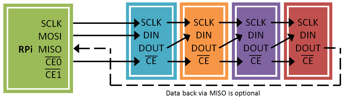
We need to do this for each row that we wish to update (or use MAX7219_NOOP if we want to keep the current row the same). This is known as a daisy-chain SPI configuration, supported by some SPI devices, where data is passed through each device on the SPI bus to the next one, which allows the use of three bus control signals for multiple devices.