
18.2 Failure Mode and Effect Analysis
As discussed in prior chapters, FMEA is a detailed document that identifies ways in which a process or product can fail to meet critical requirements. It is a living document that lists all the possible causes of failure from which a list of items can be generated to determine types of controls or where changes in the procedures should be made to reduce or mitigate risk. The FMEA also allows procedure developers to prioritize and track procedure changes (1). The process is effective because it provides a very systematic process for evaluating a system or a procedure, in this instance. It provides a means for identifying and documenting
FMEA can be used to analyze the following:
A procedure analysis will be used to demonstrate how an FMEA can be conducted. An FMEA is conducted on a step-by-step basis. Table 18.1 shows an example of an FMEA table. The following constitutes the steps of an FMEA. These steps will be illustrated by use of an example.
Table 18.1 Example of FMEA Table
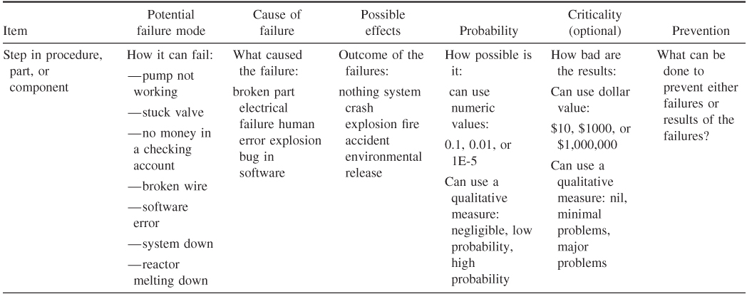
The first step is to create a flow diagram of the procedure. This is a relatively simple process in which a table or block diagram is constructed that shows the steps in the procedure. Table 18.2 shows the simple steps for checking an engine chip detector. Note that this is a simple example and not an exhaustive analysis. Table 18.3 lists the major, credible failures associated with each step in the process. Table 18.4 shows the effect of the potential failures. Table 18.5 shows the complete FMEA for the task.
Table 18.2 Process Steps for Checking a Chip Detector
| Inspecting chip detector | |
| Step number | Process steps |
| 1 | Cut and remove lock wire from oil drain Plug |
| 2 | Remove oil drain plug |
| 3 | Drain oil |
| 4 | Cut and remove lock wire from chip detector |
| 5 | Remove chip detector |
| 6 | Examine chip detector |
| 7 | Clean chip detector |
| 8 | Replace chip detector |
| 9 | Lock wire chip detector |
| 10 | Replace oil drain plug |
| 11 | Lock wire oil drain plug |
| 12 | Replace oil |
Table 18.3 Failures Associated with Each Step
| Inspecting chip detector | |
| Process steps | Major failures |
| Cut and remove lock wire from oil drain plug | No major failures that affect process outcome |
| Remove oil drain plug | No major failures that affect process outcome |
| Drain oil | No major failures that affect process outcome |
| Cut and remove lock wire from chip detector | No major failures that affect process outcome |
| Remove chip detector | Improper removal can remove debris from chip detector and cause false reading. Chip detector can be damaged if improperly removed |
| Examine chip detector | Aircraft maintenance technician (AMT) fails to notice debris on chip detector |
| Clean chip detector | AMT fails to properly clean chip detector |
| Replace chip detector | AMT fails to properly install chip detector |
| Lock wire chip detector | AMT fails to properly lock wire chip detector |
| Replace oil drain plug | AMT fails to properly install oil drain plug |
| Lock wire oil drain plug | AMT fails to properly lock oil drain plug |
| Replace oil | AMT fails to properly replace oil |
Table 18.4 Effect of Potential Failures
| Inspecting chip detector | ||
| Process steps | Potential failure modes | Potential failure effects |
| Remove chip detector | Improper removal can remove debris from chip detector and cause false reading. Chip detector can be damaged if improperly removed | Engine could fail if chips are not properly detected. Added cost to replace damaged chip detector |
| Examine chip detector | Aircraft maintenance technician (AMT) fails to notice debris on chip detector | Engine could fail if chips are not properly detected |
| Clean chip detector | AMT fails to properly clean chip detector | Debris could be placed back into engine |
| Replace chip detector | AMT fails to properly install chip detector | Oil could leak past chip detector. Threads of chip detector could be damaged |
| Lock wire chip detector | AMT fails to properly lock wire chip detector | Chip detector could become lose and fall out, leading to loss of engine oil |
| Replace oil drain plug | AMT fails to properly install oil drain plug | Engine oil could leak out. Oil drain plug could become damaged |
| Lock wire oil drain plug | AMT fails to properly lock oil drain plug | Oil drain plug could become loose and fall out Oil drain plug could become damaged |
| Replace oil | AMT fails to properly replace oil | Engine could fail |
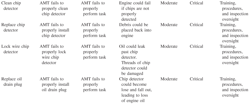
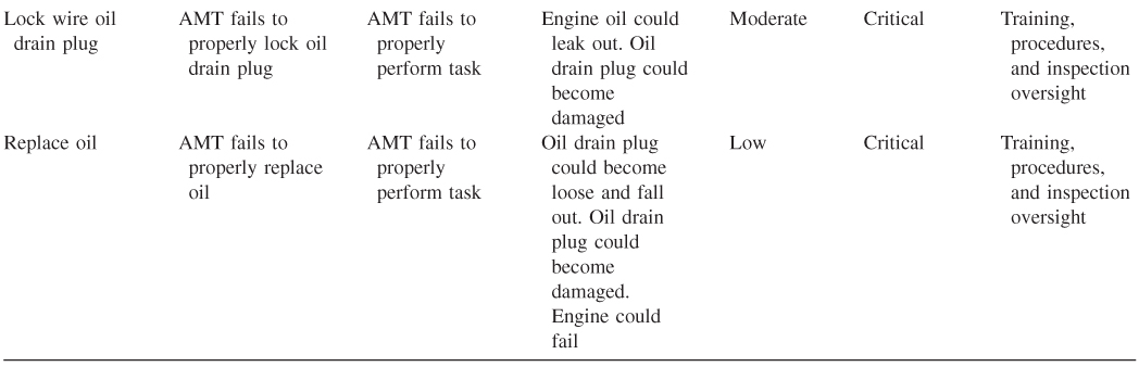
Table 18.5 Complete FMEA for Chip Detector Task
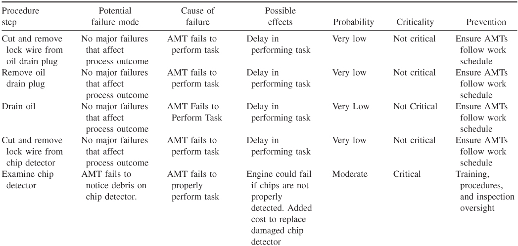
FMEA is a relatively simple but powerful tool and has a wide range of applicability for analyzing aircraft maintenance tasks.