
Network Topographies
The network topography refers to the physical layout of a network. It includes items you can touch such as cables and network devices. The primary configuration you’ll see in most networks today is star, but you may also see token ring and bus configurations. Additionally, it’s important to understand how Ethernet fits into the mix.
Network topology concepts such as bus, star, and token ring were included in an earlier version of the SSCP domain objectives and removed in the previous version. These concepts reappeared in the 2012 domain objectives, but they are listed as network topographies rather than network topologies.
Two questions came to mind for me: What’s the difference between topography and topology? Does the change imply a different focus on these concepts for a network?
Topography usually refers to maps that show physical characteristics of a land mass, such as the elevations of mountains or the physical features of an island. It can also refer to a detailed description of map features.
Topology is a study of mathematics related to spatial properties. In the context of networks, it refers to how parts of a network are interrelated with each other. It is sometimes described as the graphic description of a network, including the devices and connecting lines.
Network topology is very easy to connect to terms such as token ring, bus, star, and Ethernet. Different topologies are connected together in different ways, as shown in this section. However, it’s a little harder to connect networks with topography. For example, knowing the physical features of a router isn’t as important to administrators as knowing how a router is connected.
I’ve concluded that these are a couple of terms that are just merging for some people. In other words, in the context of the SSCP exam, there really isn’t a difference between network topology and network topography. However, if you’re a map maker or a mathematician, you should be aware of the differences.
Ethernet
The IEEE 802.3 family of standards defines Ethernet. It is the most widely used standard for local area networks (LANs). It’s been around since 1973 and includes many different modifications. For example, Gigabit Ethernet, 10 Gigabit Ethernet, and 100 Gigabit Ethernet define the standards used for sending data over a network in with higher bandwidths. IEEE 802.3 is currently being drafted and includes a revision of multiple IEEE 802.3 versions. It’s expected to be published as IEEE 802.3-2012 in March 2012.
When discussing Ethernet, it’s worth mentioning Carrier Sense Multiple Access and collisions. A collision occurs when two devices try to communicate at the same time. Since both devices are sending traffic, the data from both systems collides with each other and none of the data is readable. There are two ways of detecting and dealing with collisions if the systems are using the same wire for sending and receiving: Collisions can be detected or avoided.
CSMA/CD
Ethernet networks support Carrier Sense Multiple Access/Collision Detection (CSMA/CD). In CSMA/CD, each of the devices on the network can detect collisions. As soon as a device detects a collision, it sends a signal on the wire letting all other systems know that a collision occurred. Each device then waits a random amount of time before resending.
However, most switches and computers today use full duplex connections. In other words, the cable connecting a switch and a computer includes two sets of wires, with one set of wires used for receiving and another set of wires used for transmitting. If full duplex is used, and each device is directly connected with only one other device, collisions don’t occur.
Unfortunately, some older devices still use half-duplex. In a half-duplex connection, only a single set of wires is used for both transmitting and receiving. It’s possible for one system to transmit at the same time as another device is transmitting, resulting in a collision. Ethernet supports CSMA/CD for backward compatibility.
CSMA/CA
In Carrier Sense Multiple Access/Collision Avoidance (CSMA/CA), systems listen before transmitting data. If they sense that other systems are transmitting data, they wait a random amount of time to check again before sending traffic. Wireless networks such as 802.11 networks use CSMA/CA.
Wireless networks also support Request To Send (RTS) and Clear To Send (CTS) to negotiate traffic. When a computer wants to transmit data, it sends out the RTS signal. The destination replies with a CTS and waits for the transmission.
Bus
In a bus configuration, all of the hosts are connected together via a single shared cable connection. In other words, all systems are directly connected to each other via the bus. The bus configuration was commonly used in earlier networks since it was easy to set up. However, it is very difficult to troubleshoot, so it is rarely used to connect network computers together today.
The cable used in a bus configuration is commonly coaxial cable. This is similar to what is used for a TV cable. T connectors are used to connect each computer on the network. In other words, the cable connects to one end of the T, the T connects to the computer, and the other end of the T goes to the next computer.
Figure 3-4 shows a bus configuration. Notice that each end of the bus includes a terminator. When an electrical signal travels down a wire, it will reflect back when it reaches the end unless it is terminated. The terminator is a connector that ensures that the signal is not reflected back. However, if the terminator is not installed, the reflection will interfere with all the transmissions, essentially taking the network down.
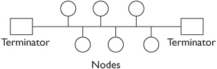
Think back to how the computers are connected with a T to the main bus. If any one of these T connections is disconnected, you no longer have a single bus with two terminators. Instead, you have two buses, and each one only has a single terminator instead of two terminators. In other words, none of the computers will be able to communicate on the network.
If you only have three or four computers on your network, you can probably locate the problem relatively easily. However, if the network includes several hundred computers, it can take quite a long time to discover the problem.
Older Ethernet standards for bus configurations include 10Base2 (ThinNet) and 10Base5 (ThickNet). These are thin and thick coaxial type cables used with bus configurations.

EXAM TIP Bus networks are expensive to maintain, reducing availability. A single break in the cable takes down the entire network.
Star
In a star configuration, all the devices are connected to a central device such as a hub, switch, or router, as shown in Figure 3-5. When drawn this way, it is reminiscent of a star, which is how it gets its name.


NOTE Many network diagrams are drawn similar to a bus configuration diagram but are actually configured in a star. In other words, network diagrams usually don’t indicate whether the network is configured as a bus, star, or token ring. Instead, they show the relevant components, such as the computers and servers.
This configuration is much more common in typical computer networks today. Additionally, the devices typically connect with unshielded twisted pair cable (UTP) or shielded twisted pair (STP). UTP and STP cable uses RJ-45 connectors and is usually Category (CAT) 5, 5E, 6, or 6a. Cat 6 and 6a cable can be used with 10GBase-T supporting 10 GB bandwidths.
A typical star configuration uses a switch as the central component, and computers connect to the switch as nodes in the star. Each of the computers is connected to the switch using UTP or STP cables, and each of these computers can communicate to other computers via the switch. Terminators are not required in a star configuration as they are in a bus configuration.
Networks configured in a star are much easier to troubleshoot. If a cable is disconnected from a single computer, only that computer is affected. All the other computers will still work. However, compared to the bus configuration, you need much more cable. Each device uses a separate cable from it to the device.
The central device in a star configuration could be a hub, but most organizations replace hubs with switches. When a hub is used, all traffic that goes in one port goes out all the other ports of the hub. However, a switch directs unicast traffic to only one other port based on the destination computer’s Media Access Control (MAC) address. This improves network efficiency by limiting traffic to computers, but it also reduces the potential of sniffing attacks.
If a hub is used as a central device, an attacker can install a protocol analyzer (sniffer) on any computer connected to the hub. If a switch is used, the only traffic that will reach this attacker is traffic that is directly addressed to or from the attacker’s computer.
Switches do have monitoring ports, though, and the monitoring port can be used to view all traffic to or from a switch. If an attacker has physical access to the switch, the attacker can connect to the monitoring port and sniff all the traffic. Because of this, switches are commonly kept in secure areas, such as in a locked wiring closet or a locked server room.
Securing a switch in a wiring closet or server room provides security, but also increases the cost of the cable. Each device needs to have longer cables to connect to the switch.
Ethernet standards for star configurations using twisted pair include 10BaseT, 100Base-TX, and 1000Base-T, supporting bandwidths of 10 MB bit/s, 100 MB bit/s, and 1 GB bit/s, respectively.
Token Ring
In a token ring network, each device is connected together in a ring. Additionally, the ring includes a logical token that controls when computers can communicate. Computers can send traffic on the network only when they have the token.
For example, consider a group of five people in a room sitting in a circle. Each person can talk, but only while holding a piece of paper identified as a token. Each person takes turns talking, and after talking they pass the token to the next person in the ring.
Figure 3-6 shows two diagrams of a token ring. The diagram on the left shows what the original typical token ring networks looked like. Each computer is connected to one other computer in the ring and they pass the token around the network. If a computer has the token, it can send traffic on the network. However, if any of the computers fails or is disconnected from the network, it breaks the ring. No other computers will be able to communicate.

Figure 3-6 Token ring configuration
The configuration on the right includes a multistation access unit (MSAU), which is sometimes called a media access unit (MAU). The traffic still flows logically in a circle, but it goes through the MSAU. For example, Computer B isn’t connected directly to Computer A or Computer C, but instead to the MSAU. Traffic passes from Computer A to the MSAU, then to Computer B, back to the MSAU, and then to Computer C. If a computer fails, or a connection between the MSAU and a computer breaks, the MSAU senses the failure and bypasses the computer. In other words, a single failure does not take down the entire network.
Token ring networks don’t scale well. In other words, adding more computers significantly reduces performance. If a token ring has five computers, each computer has the token about 20 percent of the time. However, if the token ring has 100 computers, each computer has the token for only about 1 percent of the time. Traffic can slow to a crawl.
An extension of token ring networks is the Fiber Distributed Data Interface (FDDI) standard. It uses fiber-optic connections instead of copper connections and thus supports much higher bandwidth. It also uses dual rings for fault tolerance. Conventional token ring networks support speeds up to 16 MB/s. However, FDDI token rings support speeds up to 100 MB/s over distances as far away as 124 miles.