
Day 11. Object-Oriented Analysis and Design
It is easy to become focused on the syntax of C++ and to lose sight of how and why you use these techniques to build programs.
Today, you will learn
• How to use object-oriented analysis to understand the problem you are trying to solve
• How to use object-oriented design to create a robust, extensible, and reliable solution
• How to use the Unified Modeling Language (UML) to document your analysis and design
Building Models
If complexity is to be managed, a model of the universe must be created. The goal of the model is to create a meaningful abstraction of the real world. Such an abstraction should be simpler than the real world but should also accurately reflect the real world so that the model can be used to predict the behavior of things in the real world.
A child’s globe is a classic model. The model isn’t the thing itself; a child’s globe would never be confused with the Earth, but one maps the other well enough that you can learn about the Earth by studying the globe.
There are, of course, significant simplifications. My daughter’s globe never has rain, floods, globe-quakes, and so forth, but I can use her globe to predict how long it will take me to fly from my home to Indianapolis should I ever need to come in and explain myself to the Sams senior management when they ask me why my manuscript was late (“you see, I was doing great, but then I got lost in a metaphor and it took me hours to get out”).
A model that is not simpler than the thing being modeled is not much use. The comedian Steve Wright quips: “I have a map on which one inch equals one inch. I live at E5.”
Object-oriented software design is about building good models. It consists of two significant pieces: a modeling language and a process.
Software Design: The Modeling Language
The modeling language is the least important aspect of object-oriented analysis and design; unfortunately, it tends to get the most attention. A modeling language is nothing more than a convention for representing a model in some other medium such as paper or a computer system, and in some format such as graphics, text, or symbols. For example, you can easily decide to draw your classes as triangles and draw the inheritance relationship as a dotted line. If so, you might model a geranium as shown in Figure 11.1.
Figure 11.1. Generalization/specialization.
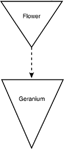
In the figure, you see that a Geranium is a special kind of Flower. If you and I agree to draw our inheritance (generalization/specialization) diagrams like this, we’ll understand each other perfectly. Over time, we’ll probably want to model lots of complex relationships, and so we’ll develop our own complicated set of diagramming conventions and rules.
Of course, we’ll need to explain our conventions to everyone else with whom we work, and each new employee or collaborator will have to learn our conventions. We might interact with other companies that have their own conventions, and we’ll need to allow time to negotiate a common convention and to compensate for the inevitable misunderstandings.
It would be more convenient if everyone in the industry agreed on a common modeling language. (For that matter, it would be convenient if everyone in the world agreed on a single spoken language, but one thing at a time.)
The lingua franca of software analysis and design is UML—the Unified Modeling Language. The job of the UML specification is to answer questions such as, “How should we draw an inheritance relationship?” The geranium drawing shown in Figure 11.1 would be drawn in UML as shown in Figure 11.2.
Figure 11.2. UML drawing of specialization.
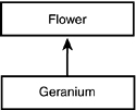
In UML, classes are drawn as rectangles, and inheritance is drawn as a line with an arrowhead. Interestingly, the arrowhead points from the more specialized class to the more general class. The direction of the arrow can be counterintuitive, but it doesn’t matter; as long as we all agree, then after we learn the representation, we can communicate.
The details of the UML are rather straightforward. The diagrams generally are not hard to use or to understand, and you’ll learn about them as they are presented. Although it is possible to write a whole book on the UML, the truth is that 90 percent of the time, you use only a small subset of the UML notation, and that subset is easily learned.
Software Design: The Process
The process of object-oriented analysis and design is much more complex and important than the modeling language. So, of course, it is ironic that you hear much less about it.
That is because the debate about modeling languages is pretty much settled; as an industry, it has been decided that UML is the primary standard to be used. The debate about process, however, rages on.
A method is a modeling language and a process. Method is often incorrectly referred to as “methodology,” but “methodology” is the study of methods.
A methodologist is someone who develops or studies one or more methods. Typically, methodologists develop and publish their own methods. Three of the leading methodologists and their methods are Grady Booch, who developed the Booch method, Ivar Jacobson, who developed object-oriented software engineering, and James Rumbaugh, who developed Object Modeling Technology (OMT). Together, these three men have created what is now called the Rational Unified Process (formerly known as Objectory), a method and a commercial product from Rational Software, Inc. All three men have been employed at IBM’s Rational Software division, where they are affectionately known as the Three Amigos.
Today’s lesson loosely follows their process rather than slavishly adhering to academic theory—it is much more important to ship a product than to adhere to a method. Other methods have something to offer, and so you will learn the bits and pieces that are valuable to use when stitching together a workable framework. Not every practitioner agrees with this approach, and you are encouraged to read the extensive literature on software engineering practice to determine what you think is the best practice. If you work for a company that follows a specific method as their official practice, you need to be prepared to follow that method to the level of compliance they require.
The process of software design can be iterative. In that case, as software is developed, you can go through the entire process repeatedly as you strive to enhance your understanding of the requirements. The design directs the implementation, but the details uncovered during implementation feed back into the design. In this approach, you should not try to develop any sizable project in a single, orderly, straight line; rather, you should iterate over pieces of the project, constantly improving your design and refining your implementation.
Waterfall Versus Iterative Development
Iterative development can be distinguished from waterfall development. In waterfall development, the output from one stage becomes the input to the next. Just like you can’t easily go up a waterfall, with this method of development, there is no going back to previous stages (see Figure 11.3).
Figure 11.3. The waterfall method.
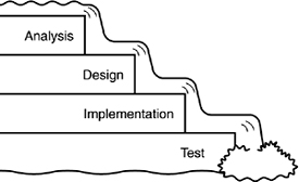
In a waterfall development process, the requirements are detailed, and the clients sign off (“Yes, this is what I want”); the requirements are then passed on to the designer, set in stone. The designer creates the design (and a wonder to behold it is), and passes it off to the programmer who implements the design. The programmer, in turn, hands the code to a QA person who tests the code and then releases it to the customer. Great in theory, however, this is potentially disastrous in practice.
The Process of Iterative Development
In iterative development, you start with a concept; an idea of what you might want to build. As the details are examined, the vision might grow and evolve.
When you have a good start on the requirements, you begin the design, knowing full well that the questions that arise during design might cause modifications back in the requirements. As you work on design, you can also begin prototyping and then implementing the product. The issues that arise in development feed back into design and might even influence your understanding of the requirements. Most important, you design and implement only pieces of the full product, iterating over the design and implementation phases repeatedly.
Although the steps of the process are repeated iteratively, it is nearly impossible to describe them in such a cyclical manner. Therefore, the following list describes them in sequence.
The following are the steps of the iterative development process you’ll use for this:
Step 1: Conceptualization
Conceptualization is the “vision thing.” It is the single sentence that describes the great idea.
Step 2: Analysis
Analysis is the process of understanding the requirements.
Design is the process of creating the model of your classes, from which you will generate your code.
Step 4: Implementation
Implementation is writing it in code (for example, in C++).
Step 5: Testing
Testing is making sure that you did it right.
Step 6: Rollout
Rollout is getting it to your customers.
Note
These are not the same as the phases of the Rational Unified Process, which are
• Inception
• Elaboration
• Construction
• Transition
Or the workflows of the Rational Unified Process, which are
• Business Modeling
• Requirements
• Analysis and Design
• Implementation
• Test
• Deployment
• Configuration and Change Management
• Project Management
• Environment
Don’t misunderstand—in reality, you run through each of these steps many times during the course of the development of a single product. The iterative development process is just hard to present and understand if you cycle through each step.
This process should sound easy. All the rest of today’s lesson is simply the details.
Step 1: The Conceptualization Phase: Starting with The Vision
All great software starts with a vision. One individual has an insight into a product he thinks would be good to build. In a business, someone envisions a product or service he wants the business to create or offer. Rarely do committees create compelling visions.
The very first phase of object-oriented analysis and design is to capture this vision in a single sentence (or at most, a short paragraph). The vision becomes the guiding principle of development, and the team that comes together to implement the vision ought to refer back to it—and update it if necessary—as it goes forward.
Even if the vision statement comes out of a committee in the marketing department, one person should be designated as the “visionary.” It is her job to be the keeper of the sacred light. As you progress, the requirements will evolve. Scheduling and time-to-market demands might (and should) modify what you try to accomplish in the first iteration of the program, but the visionary must keep an eye on the essential idea, to ensure that whatever is produced reflects the core vision with high fidelity. It is this ruthless dedication—this passionate commitment—that sees the project through to completion. If you lose sight of the vision, your product is doomed.
The conceptualization phase, in which the vision is articulated, is very brief. It might be no longer than a flash of insight followed by the time it takes to write down what the visionary has in mind. In other projects, the vision requires a complex and sometimes challenging “scoping” phase, in which agreement on the components of the vision must be generated between the people or groups involved. In such a process, what’s in and what’s out can be a key determinant of the success of the project, especially because this effort is usually when initial estimates of costs are set forth.
Often, as the object-oriented expert, you join the project after the vision has been articulated.
Step 2: The Analysis Phase: Gathering Requirements
Some companies confuse the vision statement with the requirements. A strong vision is necessary, but it is not sufficient. To move on to design, you must understand how the product will be used and how it must perform. The goal of the analysis phase is to articulate and capture these requirements. The outcome of the analysis phase is the production of a requirements document. The first section in the requirements document is the use-case analysis.
Use Cases
The driving force in analysis, design, and implementation is the use cases. A use case is nothing more than a high-level description of how the product will be used. Use cases drive not only the analysis, but they also drive the design, they help you determine the classes, and they are especially important in testing the product.
Creating a robust and comprehensive set of use cases might be the single most important task in analysis. It is here that you depend most heavily on your domain experts—those experts having the most information about the business requirements you are trying to capture.
Use cases pay little attention to the details of the user interface, and they pay no attention to the internals of the system you are building. Rather, they should be focused on the interactions that need to occur and those people and systems (called actors) that will need to be working together to produce the desired results.
To summarize, the following are some definitions:
• Use case—A description of how the software will be used
• Domain experts—People with expertise in the domain (area) of business for which you are creating the product
• Actor—Any person or system that interacts with the system you are developing
A use case is a description of the interaction between an actor and the system itself. For purposes of use-case analysis, the system is treated as a “black box.” An actor “sends a message” to the system, and something happens: Information is returned; the state of the system is changed; the spaceship changes direction; whatever.
Use cases are not sufficient to capture all of the requirements, but they are a key component and often receive the most attention. Other items might include business rules, data elements, and technical requirements for performance, security, and so on.
Identifying the Actors
It is important to note that not all actors are people. Systems that interact with the system you are building are also actors. Thus, if you are building an automated teller machine (ATM), the customer and the bank clerk can both be actors—as can other systems with which the new system interacts, such as a mortgage-tracking or student-loan system. The essential characteristics of actors are as follows:
• They are external to the system.
• They interact with the system.
Tip
Getting started is often the hardest part of use-case analysis. Often, the best way to get going is with a “brainstorming” session. Simply write down the list of people and systems that will interact with your new system. Remember that people really means roles—the bank clerk, the manager, the customer, and so forth. One person can have more than one role.
For the ATM example just mentioned, the list of roles would include the following:
• The customer
• The bank personnel
• A back-office system
• The person who fills the ATM with money and supplies
No need exists to go beyond the obvious list at first. Generating even three or four actors might be enough to get you started on generating use cases. Each of these actors interacts with the system in different ways. You need to capture these interactions in the use cases.
Determining the First Use Cases
You have to start somewhere. For the ATM example, start with the customer role. What are the actions for the customer role? Brainstorming could lead to the following use cases for a customer:
• Customer checks his balances.
• Customer deposits money to his account.
• Customer withdraws money from his account.
• Customer transfers money between accounts.
• Customer opens an account.
• Customer closes an account.
Should you distinguish between “Customer deposits money in his checking account” and “Customer deposits money in his savings account,” or should these actions be combined (as they are in the preceding list) into “Customer deposits money to his account?” The answer to this question lies in whether this distinction is meaningful in the domain (the domain is the real-world environment being modeled—in this case, banking).
To determine whether these actions are one use case or two, you must ask whether the mechanisms are different (does the customer do something significantly different with these deposits) and whether the outcomes are different (does the system reply in a different way). The answer to both questions for the deposit issue is “no”: The customer deposits money to either account in essentially the same way, and the outcome is pretty much the same; the ATM responds by incrementing the balance in the appropriate account.
Given that the actor and the system behave and respond more or less identically, regardless of whether the deposit is made to the checking or to the savings account, these two use cases are actually a single use case. Later, when the use-case scenarios are fleshed out, you can try the two variations to see whether they make any difference at all.
As you think about each actor, you might discover additional use cases by asking these questions:
• Why is the actor using this system?
The customer is using the system to get cash, to make a deposit, or to check an account balance.
• What outcome does the actor want or expect from each request?
Add cash to an account or get cash to make a purchase.
• What happened to cause the actor to use this system now?
She might recently have been paid or might be on the way to make a purchase.
• What must the actor do to use the system?
Identify herself by putting an ATM card into the slot in the machine.
Aha! We need a use case for the customer logging in to the system.
• What information must the actor provide to the system?
Enter a Personal ID number.
Aha! We need use cases for obtaining and editing the Personal ID number.
• What information does the actor hope to get from the system?
Balances, and so on.
You can often find additional use cases by focusing on the attributes of the objects in the domain. The customer has a name, a PIN, and an account number; do you have use cases to manage these objects? An account has an account number, a balance, and a transaction history; have these elements been captured in the use cases?
After the customer use cases have been explored in detail, the next step in fleshing out the list of use cases is to develop the use cases for each of the other actors. The following list shows a reasonable first set of use cases for the ATM example:
• Customer checks his balances.
• Customer deposits money to his account.
• Customer withdraws money from his account.
• Customer transfers money between accounts.
• Customer opens an account.
• Customer closes an account.
• Customer logs in to his account.
• Customer checks recent transactions.
• Bank clerk logs in to special management account.
• Bank clerk makes an adjustment to a customer’s account.
• A back-office system updates a user’s account based on external activity.
• Changes in a user’s account are reflected in a back-office system.
• The ATM signals it is out of cash to dispense.
• The bank technician fills the ATM with cash and supplies.
Creating the Domain Model
After you have a first cut at your use cases, the requirements document can be fleshed out with a detailed domain model. The domain model is a document that captures all you know about the domain (the field of business you are working in). As part of your domain model, you create domain objects that describe all the objects mentioned in your use cases. So far, the ATM example includes these objects: customer, bank personnel, back-office systems, checking account, savings account, and so forth.
For each of these domain objects, you need to capture essential data, such as the name of the object (for example, customer, account, and so on), whether the object is an actor, the object’s principal attributes and behavior, and so forth. Many modeling tools support capturing this information in “class” descriptions. Figure 11.4 shows how this information is captured with the Rational Rose modeling tool.
Figure 11.4. Rational Rose.
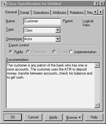
It is important to realize that what is being described here is not the class that will be used in the design (even though there will probably be similar classes used in the design), but rather classes of objects in the requirements domain. This is documentation of what the requirements will demand of the system, not documentation of how the system will meet those requirements.
You can diagram the relationship among the objects in the domain of the ATM example using the UML—with the same diagramming conventions that will be used later to describe the relationships among classes in the design. This is one of the great strengths of the UML: You can use the similar representations at every stage of the project.
For example, you can capture that checking accounts and savings accounts are both specializations of the more general concept of bank account by using the UML conventions for classes and generalization relationships, as shown in Figure 11.5.
Figure 11.5. Specialization.
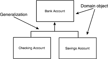
In the diagram in Figure 11.5, the boxes represent the various domain objects, and the line with an arrowhead indicates generalization. The UML specifies that this line is drawn from the specialized class to the more general “base” class. Thus, both Checking Account and Savings Account point up to Bank Account, indicating that each is a specialized form of Bank Account.
Again, it is important to note that what is being shown at this time are the relationships among classes in the requirements domain. Later, you might decide to have a CheckingAccount object in your design as well as a BankAccount object, and you can implement this relationship using inheritance; but these are design-time decisions. At analysis time, all you are documenting is your understanding of these requirements domain.
The UML is a rich modeling language, and you can capture any number of relationships. The principal relationships captured in analysis, however, are as follows:
• Generalization (or specialization)
• Containment
• Association
Generalization
Generalization is often equated with “inheritance,” but a sharp and meaningful distinction exists between the two. Generalization describes the relationship; inheritance is the programming implementation of generalization. Inheritance is how generalization is manifested in code. The other side of the generalization coin is specialization. A cat is a specialized form of animal; animal is a generalized concept that unifies cat and dog.
Specialization implies that the derived object is a subtype of the base object. Thus, a checking account is a bank account. The relationship is symmetrical: Bank account generalizes the common behavior and attributes of checking and savings accounts.
During domain analysis, you should seek to capture these relationships as they exist in the real world.
Containment
Often, one object is composed of many subobjects. For example, a car is composed of a steering wheel, tires, doors, radio, and so forth. A checking account is composed of a balance, a transaction history, a customer ID, and so on. The checking account has these items; containment models the “has a” relationship. The UML illustrates the containment relationship by drawing a line with a diamond from the containing object to the contained object, as shown in Figure 11.6.
Figure 11.6. Containment.
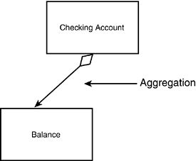
The diagram in Figure 11.6 suggests that the Checking Account has a Balance. You can combine these diagrams to show a fairly complex set of relationships (see Figure 11.7).
Figure 11.7. Object relationships.
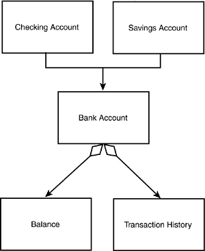
The diagram in Figure 11.7 states that a Checking Account and a Savings Account are both Bank Accounts, and that all Bank Accounts have both a Balance and a Transaction History.
Association
The third relationship commonly captured in the domain analysis is a simple association. An association suggests that two objects interact in some way, without being terribly precise about what that way actually might be. This definition will become much more precise in the design stage, but for analysis, it is only being suggested that Object A and Object B interact, but that neither contains the other and neither is a specialization of the other. This association is shown in the UML with a simple straight line between the objects, as shown in Figure 11.8.
Figure 11.8. Association.

The diagram in Figure 11.8 indicates that Object A associates in some way with Object B.
Establishing Scenarios
Now that you have a preliminary set of use cases and the tools with which to diagram the relationship among the objects in the domain, you are ready to formalize the use cases and give them more depth.
Each use case can be broken into a series of scenarios. A scenario is a description of a specific set of circumstances that distinguish among the various elements of the use case. For example, the use case “Customer withdraws money from his account” might have the following scenarios:
• Customer requests a $300 withdrawal from checking, takes the cash from the cash slot, and the system prints a receipt.
• Customer requests a $300 withdrawal from checking, but his balance is $200. Customer is informed that not enough cash is in the checking account to accomplish the withdrawal.
• Customer requests a $300 withdrawal from checking, but he has already withdrawn $100 today and the limit is $300 per day. Customer is informed of the problem, and he chooses to withdraw only $200.
• Customer requests a $300 withdrawal from checking, but the receipt roll is out of paper. Customer is informed of the problem, and he chooses to proceed without a receipt.
And so forth. Each scenario explores a variation on the original use case. Often, these variations are exception conditions (not enough money in account, not enough money in machine, and so on). Sometimes, the variations explore nuances of decisions in the use case itself. (For example, did the customer want to transfer money before making the withdrawal?)
Not every possible scenario must be explored. Rather, you are looking for those scenarios that tease out requirements of the system or details of the interaction with the actor.
Establishing Guidelines
As part of your method, you need to create guidelines for documenting each scenario. You capture these guidelines in your requirements document. Typically, you need to ensure that each scenario includes the following:
• Preconditions—What must be true for the scenario to begin
• Triggers—What event causes the scenario to begin
• What actions the actors take
• What results or changes are caused by the system
• What feedback the actors receive
• Whether repeating activities occur, and what causes them to conclude
• A description of the logical flow of the scenario
• What causes the scenario to end
• Postconditions—What must be true when the scenario is complete
In addition, you need to name each use case and each scenario. Thus, you might have the following situation:
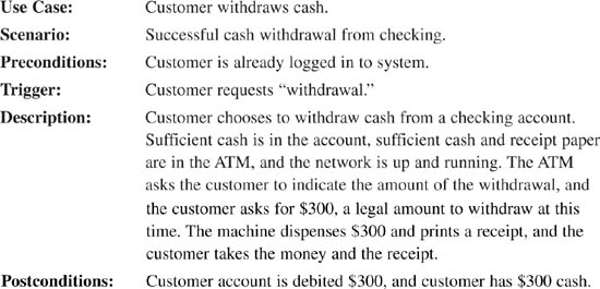
This use case can be shown with the incredibly simple diagram given in Figure 11.9.
Figure 11.9. Use-case diagram.
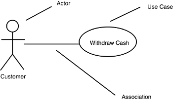
Little information is captured here except a high-level abstraction of an interaction between an actor (the customer) and the system. This diagram becomes slightly more useful when you show the interaction among use cases. I say only slightly more useful because only two interactions are possible: <<uses>> and <<extends>>. The <<uses>> stereotype indicates that one use case is a superset of another. For example, it isn’t possible to withdraw cash without first logging in. This relationship can be shown with the diagram in Figure 11.10.
Figure 11.10. The <<uses>> stereotype.
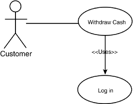
Figure 11.10 indicates that the Withdraw Cash use case “uses” the Log In use case, and, thus, Log In is a part of Withdraw Cash.
The <<extends>> use case was intended to indicate conditional relationships and something akin to inheritance, but so much confusion exists in the object-modeling community about the distinction between <<uses>> and <<extends>> that many developers have simply set aside <<extends>>, feeling that its meaning is not sufficiently well understood. Personally, I use <<uses>> when I would otherwise copy and paste the entire use case in place, and I use <<extends>> when I only use the use case under certain definable conditions.
Interaction Diagrams
Although the diagram of the use case itself might be of limited value, you can associate diagrams with the use case that can dramatically improve the documentation and understanding of the interactions. For example, you know that the Withdraw Cash scenario represents the interactions among the following domain objects: customer, checking account, and the user interface. You can document this interaction with an interaction diagram (also called a collaboration diagram), as shown in Figure 11.11.
Figure 11.11. UML interaction diagram.
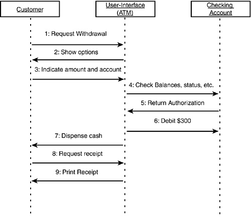
The interaction diagram in Figure 11.11 captures details of the scenario that might not be evident by reading the text. The objects that are interacting are domain objects, and the entire ATM/UI is treated as a single object, with only the specific bank account called out in any detail.
This rather simple ATM example shows only a fanciful set of interactions, but nailing down the specifics of these interactions can be a powerful tool in understanding both the problem domain and the requirements of your new system.
Creating Packages
Because you generate many use cases for any problem of significant complexity, the UML enables you to group your use cases in packages.
A package is like a directory or a folder—it is a collection of modeling objects (classes, actors, and so forth). To manage the complexity of use cases, you can create packages aggregated by whatever characteristics make sense for your problem. Thus, you can aggregate your use cases by account type (everything affecting checking or savings), by credit or debit, by customer type, or by whatever characteristics make sense to you. More important, a single use case can appear in different packages, allowing you great flexibility.
Application Analysis
In addition to creating use cases, the requirements document must capture your customer’s assumptions, and any constraints or requirements concerning hardware and operating systems, security, performance, and so forth. These requirements are your particular customer’s prerequisites—those things that you would normally determine during design and implementation but that your client has decided for you.
The application requirements (sometimes called “technical requirements”) are often driven by the need to interface with existing systems. In this case, understanding what the existing systems do and how they work is an essential component of your analysis.
Ideally, you analyze the problem, design the solution, and then decide which platform and operating system best fits your design. That scenario is as ideal as it is rare. More often, the client has a standing investment in a particular operating system or hardware platform. The client’s business plan depends on your software running on the existing system, and you must capture these requirements early and design accordingly.
Systems Analysis
Some software is written to stand alone, interacting only with the end user. Often, however, you will be called on to interface to an existing system. Systems analysis is the process of collecting all the details of the systems with which you will interact. Will your new system be a server, providing services to the existing system, or will it be a client? Will you be able to negotiate an interface between the systems, or must you adapt to an existing standard? Will the other system be stable, or must you continually hit a moving target?
These and related questions must be answered in the analysis phase, before you begin to design your new system. In addition, you need to try to capture the constraints and limitations implicit in interacting with the other systems. Will they slow down the responsiveness of your system? Will they put high demands on your new system, consuming resources and computing time?
Planning Documents
After you understand what your system must do and how it must behave, it is time to take a first stab at creating a time and budget document. Often, the client dictates the timeline: “You have 18 months to get this done.” Ideally, you examine the requirements and estimate the time it will take to design and implement the solution. That is the ideal; the practical reality is that most systems come with an imposed time limit and cost limit, and the real trick is to figure out how much of the required functionality you can build in the allotted time—and at the allotted cost.
Here are a couple guidelines to keep in mind when you are creating a project budget and timeline:
• If you are given a range, the outer number is probably optimistic.
• Liberty’s Law states that everything takes longer than you expect—even if you take into account Liberty’s Law.
Given these realities, it is imperative that you prioritize your work so that the most important tasks are done first. You should not expect to have time to finish—it is that simple. It is important that when you run out of time, what you have works and is adequate for a first release. If you are building a bridge and run out of time, if you didn’t get a chance to put in the bicycle path, that is too bad; but you can still open the bridge and start collecting tolls. If you run out of time and you’re only halfway across the river, that is not as good.
An essential thing to know about planning documents is that they are generally wrong. This early in the process, it is virtually impossible to offer a reliable estimate of the duration of the project. After you have the requirements, you can get a good handle on how long the design will take, a fair estimate of how long the implementation will take, and a reasonable guesstimate of the testing time. Then, you must allow yourself at least 20 to 25 percent “wiggle room,” which you can tighten as you move forward through the iterations and learn more.
The inclusion of “wiggle room” in your planning document is not an excuse to avoid planning documents. It is merely a warning not to rely on them too much early on. As the project goes forward, you’ll strengthen your understanding of how the system works, and your estimates will become increasingly precise.
Visualizations
The final piece of the requirements document is the visualization. The visualization is a fancy name for the diagrams, pictures, screen shots, prototypes, and any other visual representations created to help you think through and design the graphical user interface of your product.
For many large projects, you can develop a full prototype to help you (and your customers) understand how the system will behave. On some teams, the prototype becomes the living requirements document; the “real” system is designed to implement the functionality demonstrated in the prototype.
Artifacts
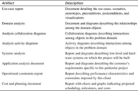
At the end of each phase of analysis and design, you will create a series of documents (often called “artifacts” or “deliverables”). Table 11.1 shows some of the artifacts of the analysis phase. Several groups use these documents. The customer will use the documents to be certain that you understand what they need. End users will use them to give feedback and guidance to the project. The project team will use them to design and implement the code. Many of these documents also provide material crucial both to your documentation team and to Quality Assurance to tell them how the system ought to behave.
Table 11.1. Artifacts Created During the Analysis Stage of Project Development
Step 3: The Design Phase
Analysis focuses on understanding the problem domain, whereas the next step of the processes, design, focuses on creating the solution. Design is the process of transforming your understanding of the requirements into a model that can be implemented in software. The result of this process is the production of a design document.
A design document can be divided into two sections: Class Design and Architectural Mechanisms. The Class Design section, in turn, is divided into static design (which details the various classes and their relationships and characteristics) and dynamic design (which details how the classes interact).
The Architectural Mechanisms section of the design document provides details about how you will implement object persistence, concurrency, a distributed object system, and so forth. The rest of today’s lesson focuses on the class design aspect of the design document; other lessons in the rest of this book explain elements of how to implement various architectural mechanisms.
What Are the Classes?
As a C++ programmer, you are now used to creating classes. Formal design methods require you to separate the concept of the C++ class from the concept of the design class, although they are intimately related. The C++ class you write in code is the implementation of the class you designed. There is a one-to-one relationship: Each class in your design corresponds to a class in your code, but don’t confuse one for the other. It is certainly possible to implement your design classes in another language, and the syntax of the class definitions might be changed.
That said, most of the time these classes are discussed without distinguishing them because the differences are highly abstract. When you say that in your model the Cat class will have a Meow() method, understand that this means that you will put a Meow() method into your C++ class as well.
You capture the design model’s classes in UML diagrams, and you capture the implementation’s C++ classes in code that can be compiled. The distinction is meaningful, yet subtle.
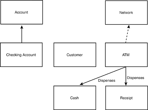
In any case, the biggest stumbling block for many novices is finding the initial set of classes and understanding what makes a well-designed class. One simplistic technique suggests writing out the use-case scenarios and then creating a class for every noun. Consider the following use-case scenario:
Customer chooses to withdraw cash from checking. Sufficient cash is in the account, sufficient cash and receipts are in the ATM, and the network is up and running. The ATM asks the customer to indicate an amount for the withdrawal, and the customer asks for $300, a legal amount to withdraw at this time. The machine dispenses $300 and prints a receipt, and the customer takes the money and the receipt.
You might pull out of this scenario the following classes:
• Customer
• Cash
• Checking
• Account
• Receipts
• ATM
• Network
• Amount
• Withdrawal
• Machine
• Money
You might then aggregate the synonyms to create this list, and then create classes for each of these nouns:
• Customer
• Cash (money, amount, withdrawal)
• Checking
• Receipts
• ATM (machine)
• Network
This is not a bad way to start, as far as it goes. You might then go on to diagram the obvious relationships among some of these classes, as shown in Figure 11.12.
Figure 11.12. Preliminary classes.
Transformations
What you began to do in the preceding section was not so much extract the nouns from the scenario as to begin transforming objects from the domain analysis into objects in the design. That is a fine first step. Often, many of the objects in the domain have surrogates in the design. An object is called a surrogate to distinguish between the actual physical receipt dispensed by an ATM and the object in your design that is merely an intellectual abstraction implemented in code.
You will likely find that most of the domain objects have a representation in the design—that is, a one-to-one correspondence exists between the domain object and the design object. Other times, however, a single domain object is represented in the design by an entire series of design objects. And at times, a series of domain objects might be represented by a single design object.
Note that in Figure 11.12, CheckingAccount has already been captured as a specialization of Account. You didn’t set out to find the generalization relationship, but this one was self-evident, so it has been captured. Similarly, from the domain analysis, you know that the ATM dispenses both Cash and Receipts, so that information has been captured immediately into the design.
The relationship between Customer and CheckingAccount is less obvious. Such a relationship exists, but the details are not obvious, so you should hold off.
Other Transformations
After you have transformed the domain objects, you can begin to look for other useful design-time objects. Often, each actor has a class. A good starting place is with the interface between your new system and any existing systems—this should be encapsulated in an interface class. However, be careful when considering databases and other external storage media. It is generally better to make it a responsibility of each class to manage its own “persistence”—that is, how it is stored and retrieved between user sessions. Those design classes, of course, can use common classes for accessing files or databases, but most commonly, the operating system or the database vendor provides these to you.
These interface classes allow you to encapsulate your system’s interactions with the other system, and, thus, shield your code from changes in the other system. Interface classes allow you to change your own design, or to accommodate changes in the design of other systems, without breaking the rest of the code. As long as the two systems continue to support the agreed-on interface, they can change independently of one another.
Data Manipulation
Similarly, you might need to create classes for data manipulation. If you have to transform data from one format into another format (for example, from Fahrenheit to Celsius or from English to Metric), you might want to encapsulate these transformations behind a special class. You can use this technique when converting data into required formats for other systems or for transmission over the Internet—in short, any time you must manipulate data into a specified format, you encapsulate the protocol behind a data manipulation class.
Views and Reports
Every “view” or “report” your system generates (or, if you generate many reports, every set of reports) is a candidate for a class. The rules behind the report—both how the information is gathered and how it is to be displayed—can be productively encapsulated inside a view class.
Devices
If your system interacts with or manipulates devices (such as printers, cameras, modems, scanners, and so forth), the specifics of the device protocol ought to be encapsulated in a class. Again, by creating classes for the interface to the device, you can plug in new devices with new protocols and not break any of the rest of your code; just create a new interface class that supports the same interface (or a derived interface), and off you go.
Building the Static Model
When you have established your preliminary set of classes, it is time to begin modeling their relationships and interactions. For purposes of clarity, the static model is explained first, and then the dynamic model. In the actual design process, you will move freely between the static and dynamic models, filling in details of both—and, in fact, adding new classes and sketching them in as you learn from each.
The static model focuses on three areas of concern: responsibilities, attributes, and relationships. The most important of these—and the one you focus on first—is the set of responsibilities for each class. The most important guiding principle is this: Each class should be responsible for one thing.
That is not to say that each class has only one method. Far from it; many classes will have dozens of methods. But all these methods must be coherent and cohesive; that is, they must all relate to one another and contribute to the class’s capability to accomplish a single area of responsibility.
In a well-designed system, each object is an instance of a well-defined and well-understood class that is responsible for one area of concern. Classes typically delegate extraneous responsibilities to other, related classes. By creating classes that have only a single area of concern, you promote the creation of highly maintainable code.
To get a handle on the responsibilities of your classes, you might find it beneficial to begin your design work with the use of CRC cards.
Using CRC Cards
CRC stands for Class, Responsibility, and Collaboration. A CRC card is nothing more than a 4×6 index card. This simple, low-tech device enables you to work with other people in understanding the primary responsibilities of your initial set of classes. You assemble a stack of blank 4×6 index cards and meet around a conference table for a series of CRC card sessions.
How to Conduct a CRC Session
For a large project or component, each CRC session should be attended, ideally, by a group of three to six people; any more becomes unwieldy. You should have a facilitator, whose job it is to keep the session on track and to help the participants capture what they learn. At least one senior software architect should be present, ideally someone with significant experience in object-oriented analysis and design. In addition, you need to include at least one or two “domain experts” who understand the system requirements and who can provide expert advice in how things ought to work.
The most essential ingredient in a CRC session is the conspicuous absence of managers. This is a creative, free-wheeling session that must be unencumbered by the need to impress one’s boss. The goal here is to explore, to take risks, to tease out the responsibilities of the classes, and to understand how they might interact with one another.
You begin the CRC session by assembling your group around a conference table, with a small stack of 4×6 index cards. At the top of each CRC card, you write the name of a single class. Draw a line down the center of the card and write Responsibilities on the left and Collaborations on the right.
Begin by filling out cards for the most important classes you’ve identified. For each card, write a one-sentence or two-sentence definition on the back. You can also capture what other class this class specializes if that is obvious at the time you’re working with the CRC card. Just write Superclass: below the class name and fill in the name of the class from which this class derives.
Focusing on Responsibilities
The point of the CRC session is to identify the responsibilities of each class. Pay little attention to the attributes, capturing only the most essential and obvious attributes as you go. The important work is to identify the responsibilities. If, in fulfilling a responsibility, the class must delegate work to another class, you capture that information under collaborations.
As you progress, keep an eye on your list of responsibilities. If you run out of room on your 4×6 card, it might make sense to wonder whether you’re asking this class to do too much. Remember, each class should be responsible for one general area of work, and the various responsibilities listed should be cohesive and coherent—that is, they should work together to accomplish the overall responsibility of the class.
At this point, you do not want to focus on relationships, nor do you want to worry about the class interface or which methods will be public and which will be private. The focus is only on understanding what each class does.
Anthropomorphic and Use-Case Driven
The key feature of CRC cards is to make them anthropomorphic—that is, you attribute humanlike qualities to each class. Here’s how it works: After you have a preliminary set of classes, return to your CRC scenarios. Divide the cards around the table arbitrarily, and walk through the scenario together. For example, return to the following scenario:
Customer chooses to withdraw cash from checking. Sufficient cash is in the account, sufficient cash and receipts are in the ATM, and the network is up and running. The ATM asks the customer to indicate an amount for the withdrawal, and the customer asks for $300, a legal amount to withdraw at this time. The machine dispenses $300 and prints a receipt, and the customer takes the money and the receipt.
Assume there are five participants in the CRC session: Amy, the facilitator and object-oriented designer; Barry, the lead programmer; Charlie, the client; Dorris, the domain expert; and Ed, a programmer.
Amy holds up a CRC card representing CheckingAccount and says “I tell the customer how much money is available. He asks me to give him $300. I send a message to the dispenser telling him to give out $300 cash.” Barry holds up his card and says “I’m the dispenser; I spit out $300 and send Amy a message telling her to decrement her balance by $300. Who do I tell that the machine now has $300 less? Do I keep track of that?” Charlie says, “I think we need an object to keep track of cash in the machine.” Ed says, “No, the dispenser should know how much cash it has; that’s part of being a dispenser.” Amy disagrees: “No, someone has to coordinate the dispensing of cash. The dispenser needs to know whether cash is available and whether the customer has enough in the account, and it has to count out the money and know when to close the drawer. It should delegate responsibility for keeping track of cash on hand—some kind of internal account. Whoever knows about cash on hand can also notify the back office when it is time to be refilled. Otherwise, that’s asking the dispenser to do too much.”
The discussion continues. By holding up cards and interacting with one another, the requirements and opportunities to delegate are teased out; each class comes alive, and its responsibilities are clarified. When the group becomes bogged down in design questions, the facilitator can make a decision and help the group move on.
Limitations of CRC Cards
Although CRC cards can be a powerful tool for getting started with design, they have inherent limitations. The first problem is that they don’t scale well. In a very complex project, you can be overwhelmed with CRC cards; just keeping track of them all can be difficult.
CRC cards also don’t capture the interrelationship among classes. Although it is true that collaborations are noted, the nature of the collaboration is not modeled well. Looking at the CRC cards, you can’t tell whether classes aggregate one another, who creates whom, and so forth. CRC cards also don’t capture attributes, so it is difficult to go from CRC cards to code. Most important, CRC cards are static; although you can act out the interactions among the classes, the CRC cards themselves do not capture this information.
In short, CRC cards are a good start, but you need to move the classes into the UML if you are to build a robust and complete model of your design. Although the transition into the UML is not terribly difficult, it is a one-way street. After you move your classes into UML diagrams, there is no turning back; you set aside the CRC cards and don’t come back to them. It is simply too difficult to keep the two models synchronized with one another.
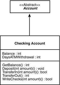
Transforming CRC Cards to UML
Each CRC card can be translated directly into a class modeled with the UML. Responsibilities are translated into class methods, and whatever attributes you have captured are added as well. The class definition from the back of the card is put into the class documentation. Figure 11.13 shows the relationship between the CheckingAccount CRC card and the UML class created from that card.
Class:CheckingAccount
SuperClass:Account
Responsibilities:
Track current balance
Accept deposits and transfers in
Write checks
Transfer cash out
Keep current day’s ATM withdrawal balance
Collaborations:
Other accounts
Back-office systems
Cash dispenser
Figure 11.13. CRC card.
Class Relationships
After the classes are in the UML, you can begin to turn your attention to the relationships among the various classes. The principal relationships you’ll model are the following:
• Generalization
• Association
• Aggregation
• Composition
The generalization relationship is implemented in C++ through public inheritance. From a design perspective, however, you focus less on the mechanism and more on the semantics: what it is that this relationship implies.
You examined the generalization relationship in the analysis phase, but now turn your attention to the objects in your design rather than to just the objects in the domain. Your efforts should now be to “factor out” common functionality in related classes into base classes that can encapsulate the shared responsibilities.
When you “factor out” common functionality, you move that functionality out of the specialized classes and up into the more general class. Thus, if you notice that both your checking and your savings account need methods for transferring money in and out, you’ll move the TransferFunds() method up into the account base class. The more you factor out of the derived classes, the more polymorphic your design will be.
One of the capabilities available in C++, which is not available in Java, is multiple inheritance (although Java has a similar, if limited, capability with its multiple interfaces). Multiple inheritance allows a class to inherit from more than one base class, bringing in the members and methods of two or more classes.
Experience has shown that you should use multiple inheritance judiciously because it can complicate both your design and the implementation. Many problems initially solved with multiple inheritance are today solved using aggregation. That said, multiple inheritance is a powerful tool, and your design might require that a single class specializes the behavior of two or more other classes.
Multiple Inheritance Versus Containment
Is an object the sum of its parts? Does it make sense to model a Car object as a specialization of SteeringWheel, Door, and Tire, as shown in Figure 11.14?
Figure 11.14. False inheritance.
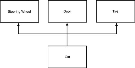
It is important to come back to the fundamentals: Public inheritance should always model generalization. The common expression for this is that inheritance should model is-a relationships. If you want to model the has-a relationship (for example, a car has-a steering wheel), you do so with aggregation, as shown in Figure 11.15.
Figure 11.15. Aggregation.
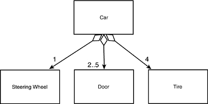
The diagram in Figure 11.15 indicates that a car has a steering wheel, four wheels, and two to five doors. This is a more accurate model of the relationship among a car and its parts. Notice that the diamond in the diagram is not filled in; this is so because this relationship is being modeled as an aggregation, not as a composition. Composition implies control for the lifetime of the object. Although the car has tires and a door, the tires and door can exist before they are part of the car and can continue to exist after they are no longer part of the car.
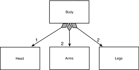
Figure 11.16 models composition. This model says that the body is not only an aggregation of a head, two arms, and two legs, but that these objects (head, arms, legs) are created when the body is created and disappear when the body disappears. That is, they have no independent existence; the body is composed of these things and their lifetimes are intertwined.
Figure 11.16. Composition.
Discriminators and Powertypes
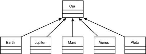
How might you design the classes required to reflect the various model lines of a typical car manufacturer? Suppose that you’ve been hired to design a system for Acme Motors, which currently manufactures five cars: the Pluto (a slow, compact car with a small engine), the Venus (a four-door sedan with a middle-sized engine), the Mars (a sport coupe with the company’s biggest engine, engineered for maximum performance), the Jupiter (a minivan with the same engine as the sports coupe but designed to shift at a lower RPM and to use its power to move its greater weight), and the Earth (a station wagon with a small engine but high RPM).
You might start by creating subtypes of car that reflect the various models, and then create instances of each model as it rolls off the assembly line, as shown in Figure 11.17.
Figure 11.17. Modeling subtypes.
How are these models differentiated? As was stated, they are differentiated by the engine size, body type, and performance characteristics. These various discriminating characteristics can be mixed and matched to create various models. This can be modeled in the UML with the discriminator stereotype, as shown in Figure 11.18.
Figure 11.18. Modeling the discriminator.
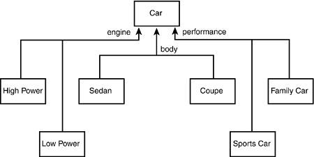
The diagram in Figure 11.18 indicates that classes can be derived from Car based on mixing and matching three discriminating attributes. The size of the engine dictates how powerful the car is, and the performance characteristics indicate how sporty the car is. Thus, you can have a powerful and sporty station wagon, a low-power family sedan, and so forth.
Each attribute can be implemented with a simple enumerator. Thus, in code, the body type might be implemented with the following statement:
enum BodyType = { sedan, coupe, minivan, stationwagon };
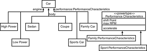
It might turn out, however, that a simple value is insufficient to model a particular discriminator. For example, the performance characteristic might be rather complex. In this case, the discriminator can be modeled as a class, and the discrimination can be encapsulated in an instance of that type.
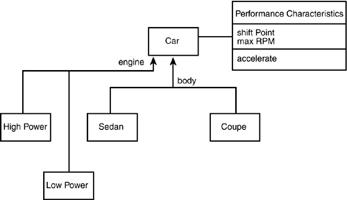
Thus, the car might model the performance characteristics in a performance type, which contains information about where the engine shifts and how fast it can turn. The UML stereotype for a class that encapsulates a discriminator, and that can be used to create instances of a class (Car) that are logically of different types (for example, SportsCar versus LuxuryCar) is <<powertype>>. In this case, the Performance class is a powertype for Car. When you instantiate Car, you also instantiate a Performance object, and you associate a given Performance object with a given Car, as shown in Figure 11.19.
Figure 11.19. A discriminator as a powertype.
Powertypes enable you to create a variety of logical types without using inheritance. You can thus manage a large and complex set of types without the combinatorial explosion you might encounter with inheritance.
Typically, you implement the powertype in C++ with pointers. In this case, the Car class holds a pointer to an instance of PerformanceCharacteristics class (see Figure 11.20). I’ll leave it as an exercise to the ambitious reader to convert the body and engine discriminators into powertypes.
Figure 11.20. The relationship between a Car object and its powertype.
Caution
Keep in mind that the practice of creating new types in this way at runtime can reduce the benefits of C++ strong typing, in which the compiler can enforce the correctness of interclass relationships. Therefore, use it carefully.
Class Car : public Vehicle
{
public:
Car();
~Car();
// other public methods elided
private:
PerformanceCharacteristics * pPerformance;
};
As a final note, powertypes enable you to create new types (not just instances) at runtime. Because each logical type is differentiated only by the attributes of the associated powertype, these attributes can be parameters to the powertype’s constructor. This means that you can, at runtime, create new types of cars on the fly. That is, by passing different engine sizes and shift points to the powertype, you can effectively create new performance characteristics. By assigning those characteristics to various cars, you can effectively enlarge the set of types of cars at runtime.
Dynamic Model
In addition to modeling the relationships among the classes, it is critical to model how they interact. For example, the CheckingAccount, ATM, and Receipt classes can interact with the Customer in fulfilling the “Withdraw Cash” use case. You now return to the kinds of sequence diagrams first used in analysis, but now flesh out the details based on the methods developed in the classes, as shown in Figure 11.21.
Figure 11.21. Sequence diagram.
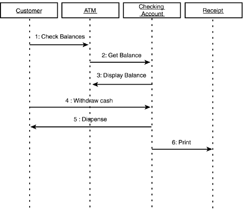
This simple interaction diagram shows the interaction among a number of design classes over time. It suggests that the ATM class delegates to the CheckingAccount class all responsibility for managing the balance, while the CheckingAccount calls on the ATM to manage display to the user.
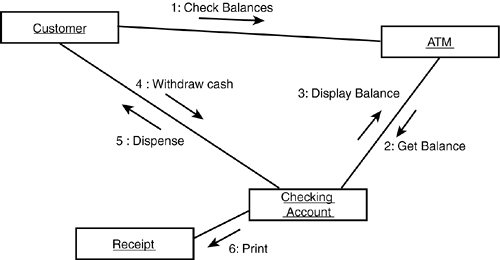
Interaction diagrams comes in two flavors. The one in Figure 11.21 is called a sequence diagram. Another view on the same information is provided by the collaboration diagram. The sequence diagram emphasizes the sequence of events over time; the collaboration diagram emphasizes the “timeless” interactions among the classes. You can generate a collaboration diagram directly from a sequence diagram; tools such as Rational Rose automate this task at the click of a button (see Figure 11.22).
Figure 11.22. Collaboration diagram.
State Transition Diagrams
As you come to understand the interactions among the objects, you also have to understand the various possible states of each individual object. You can model the transitions among the various states in a state diagram (or state transition diagram). Figure 11.23 shows the various states of the CustomerAccount class as the customer logs in to the system.
Figure 11.23. Customer account state.
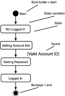
Every state diagram begins with a single start state and ends with zero or more end states. The individual states are named, and the transitions might be labeled. The guard indicates a condition that must be satisfied for an object to move from one state to another.
Super States
The customer can change her mind at any time and decide not to log in. She can do this after she swipes her card to identify her account or after she enters her password. In either case, the system must accept her request to cancel and return to the “not logged in state” (see Figure 11.24).
Figure 11.24. User can cancel.
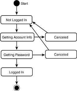
As you can see, in a more complicated diagram, the Canceled state quickly becomes a distraction. This is particularly annoying because canceling is an exceptional condition that should not be given prominence in the diagram. You can simplify this diagram by using a super state, as shown in Figure 11.25.
Figure 11.25. Super state.
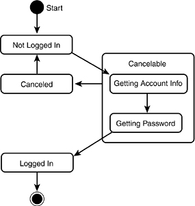
The diagram in Figure 11.25 provides the same information in Figure 11.24 but is much cleaner and easier to read. From the time you start logging in until the system finalizes your login, you can cancel the process. If you do cancel, you return to the state “not logged in.”
Steps 4–6: Implementation, Testing, and Rollout?
The remaining three stages of the processes are important, but not covered here. In regard to implementation, if you are using C++, the rest of this book covers the details. Testing and rollout are each their own complex discipline with their own demands; however, detailed coverage of them is beyond the scope of this book. Nevertheless, don’t forget that carefully testing your classes in isolation and together is key to determining that you have successfully implemented the design.
Iterations
In the Rational Unified Process, the activities listed previously are “workflows” that proceed at different levels across the phases of inception, elaboration, construction, and transition. For instance, business modeling peaks during inception but can still be occurring during construction as the review of the developed system fleshes out the requirements, whereas implementation peaks during construction, but can be occurring when prototypes are created for the elaboration phase.
Within each phase, such as construction, there can be several iterations. In the first iteration of construction, for instance, the core functions of the system can be developed; in the second iteration, those capabilities can be deepened and others added, In the third iteration, yet more deepening and addition might occur, until an iteration is reached in which the system is complete.
Summary
Today’s lesson provided an introduction to the issues involved in object-oriented analysis and design. The essence of this approach is to analyze how your system will be used (use cases) and how it must perform, and then to design the classes and model their relationships and interactions.
In the old days, ideas for what should be accomplished were sketched out and the writing of the code began quickly. The problem is that complex projects are never finished; and if they are, they are unreliable and brittle. By investing up front in understanding the requirements and modeling the design, you ensure a finished product that is correct (that is, it meets the design) and that is robust, reliable, and extensible.
Much of the rest of this book focuses on the details of implementation. Issues relating to testing and rollout are beyond the scope of this book, except to mention that you want to plan your unit testing as you implement, and that you will use your requirements document as the foundation of your test plan prior to rollout.
Q&A
Q I didn’t learn any C++ programming in today’s lesson. Why was this lesson included?
A To be effective in writing C++ programs, you have to know how to structure them. By planning and designing before you start coding, you will build better, more effective C++ programs.
Q In what way is object-oriented analysis and design fundamentally different from other approaches?
A Prior to the development of these object-oriented techniques, analysts and programmers tended to think of programs as groups of functions that acted on data. Object-oriented programming focuses on the integrated data and functionality as discrete units that have both knowledge (data) and capabilities (functions). Procedural programs, on the other hand, focus on functions and how they act on data. It has been said that Pascal and C programs are collections of procedures, and C++ programs are collections of classes.
Q Is object-oriented programming finally the silver bullet that will solve all programming problems?
A No, it was never intended to be. For large, complex problems, however, object-oriented analysis, design, and programming can provide the programmer with tools to manage enormous complexity in ways that were previously impossible.
Q Is C++ the perfect object-oriented language?
A C++ has a number of advantages and disadvantages when compared with alternative object-oriented programming languages, but it has one killer advantage above and beyond all others: It is the single most popular object-oriented programming language for writing fully executable applications. This book exists—and I’d wager you are reading it—because C++ is the development language of choice at so many corporations.
Workshop
The Workshop provides quiz questions to help you solidify your understanding of the material covered and exercises to provide you with experience in using what you’ve learned. Try to answer the quiz and exercise questions before checking the answers in Appendix D, and be certain you understand the answers before continuing to tomorrow’s lesson.
Quiz
1. What is the difference between object-oriented programming and procedural programming?
2. What are the phases of object-oriented analysis and design?
3. What is encapsulation?
4. In regard to analysis, what is a domain?
5. In regard to analysis, what is an actor?
6. What is a use case?
7. Which of the following is true?
a. A cat is a specialized form of animal.
b. Animal is a specialized form of cat and dog.
Exercises
1. A computer system is made up of a number of pieces. These include a keyboard, a mouse, a monitor, and a CPU. Draw a composition diagram to illustrate the relationship between the computer and its pieces. Hint: This is an aggregation.
2. Suppose you had to simulate the intersection of Massachusetts Avenue and Vassar Street—two typical two-lane roads, with traffic lights and crosswalks. The purpose of the simulation is to determine whether the timing of the traffic signal allows for a smooth flow of traffic.
What kinds of objects should be modeled in the simulation? What would the classes be for the simulation?
3. You are asked to design a group scheduler. The software enables you to arrange meetings among individuals or groups and to reserve a limited number of conference rooms. Identify the principal subsystems.
4. Design and show the interfaces to the classes in the room reservation portion of the program discussed in Exercise 3.