3D is one of the really cool features of WPF. It’s something that we all get very excited about. Unlike most of the other features in WPF, though, learning how to make use of 3D can be somewhat challenging. In the 3D world, you will encounter terms and concepts that are likely to be unfamiliar to many developers. Things like diffusion, materials, meshes, normals, field of view, and orthographic project.
Even so, you can do a lot given the proper tools. One such tool is ZAM 3D from Electric Rain. Although everything that we produce in this tutorial could be written by hand directly in XAML, we have found that it is very impractical. (This is coming from someone who often prefers to hand write XAML.)
Unfortunately, a trial edition of ZAM 3D isn’t available at the time of this writing. However, you can still follow along using a trial of ZAM 3D’s sister product, Swift 3D. The trial edition can be found at www.erain.com/downloads/Trials/.
(There is a 30-day money back guarantee for ZAM 3D as well.)
You can also use Blender and the XAML Exporter for Blender, both of which are free. However, there is a very steep learning curve for Blender, especially if you have no prior experience in creating 3D content.
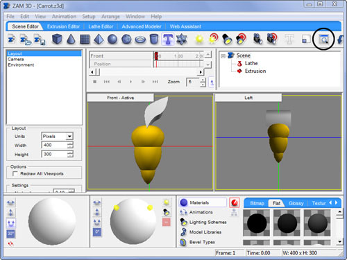
Let’s very quickly examine the interface for ZAM 3D. When you open the application for the first time, it will look like Figure B.1.
Our description here is by no means exhaustive. The documentation that comes with ZAM 3D covers this in much more detail.
Viewports—. Here we can examine the 3D scene that we are creating.
Hierarchy Toolbar—. Displays all of the models in our scene.
Animation Toolbar—. Contains the timeline and key frames for any animations.
Rotation Trackball—. Displays the currently selected model and allows us to rotate it.
Gallery Toolbar—. Allows us to easily apply animations and textures to the models in our scene.
Property Toolbar—. Various properties for adjusting your scene or selected item.
Editor Tabs—. Used for switching to the various editors ZAM 3D has available.
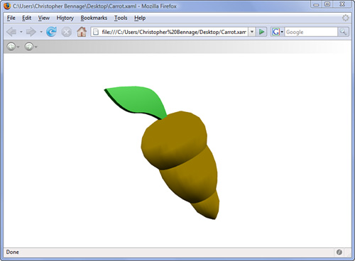
In this sweeping overview of ZAM 3D, we’re going to create a cartoonish carrot like the one shown in Figure B.2.
We’ll be able to export the 3D scene and the animation as XAML, and then place it into a real WPF application:
Open ZAM 3D. By default, you should have a brand new project.
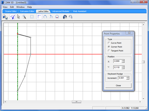
Select the Lathe Editor tab at the top. We’ll use this editor to create the main body of our carrot. The idea behind a lathe is that you create a 2D path that can be spun on an axis to produce the surface of your 3D model. I like to think of this 2D path as half of a silhouette. This technique is very useful for modeling objects such as wine glasses, candlesticks, and lamps.
By default, the Add Point Tool is selected. This is the second icon on the toolbar, and can be selected by pressing
A. Notice that we can see the X and Y position of our cursor in the status bar.Using this tool create five points, as shown in Figure B.3. Don’t worry about being precise. Just for reference, my points were located at (0,–0.2), (0.04,–0.12), (0.07,0), (0.07,0.09), and (0,0.11).
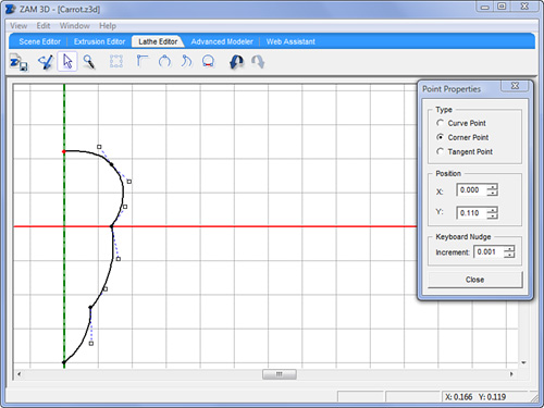
The path we drew will rotate around the Y axis. Select the Scene Editor tab at the top, and you’ll see that our “carrot” looks very angular at the moment. Switch back to the Lathe Editor.
Our carrot needs some curve. Choose the Shape Tool by pressing
Son the keyboard. The third icon on the toolbar is now selected.Drag a selection around the three middle points on the point. You can tell that a point is selected when the circle representing it is filled in.
With those three points selected, press
Ton the keyboard. This converts the selected points from corner points to tangent points. Each tangent point now has two handles that we can use to adjust the curvature of the path.Still using the Shape Tool, adjust the handles by clicking and dragging them until the path looks something like Figure B.4. You can use
Ctrl+Zto undo any adjustments, and remember that you don’t need to worry about being precise.Switch back to the Scene Editor. Our carrot is visible in the viewports. We are viewing it from the front and the left. Notice an item called “Lathe” in the Hierarchy Toolbar. This is the carrot model we just created.
Examine the Gallery Toolbar in the lower right. Select the tab labeled Flat. You’ll see a series of spheres displaying the available flat materials. Flat means “not shiny.”
Scroll down through the materials until you find a color that is sufficiently orange. If you hover your mouse over a material, a ToolTip appears, displaying its name. I chose “ER – Flat 68.”
Click and drag your selected material and drop it onto the carrot in the viewport. The material will be immediately applied to the model.
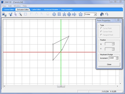
Now let’s create the leafy bit to go on top of our carrot. Select the Extrusion Editor tab from the top.
Using the Add Point tool (
A), create a shape similar to the one in Figure B.5. After adding the four points, click the first point again to close the shape. The cursor displays a+when you are over the first point. For reference, my points are located at (–0.05,0.05), (0.05,0.1), (0.06,0.015), and (–0.05,–0.05).Select the upper-left and the lower-right points using the Shape tool (
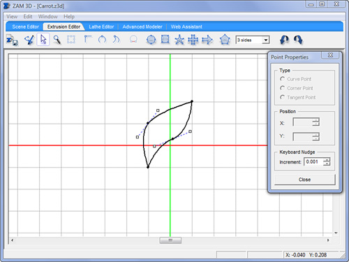
S). You can hold down Shift and drag+select them individually, but don’t hold Shift and click them.With the two points selected, press
Uto convert the corner points to curve points. Adjust the handles until the path resembles Figure B.6.Switch back the Scene Editor. In the Front viewport, you can see that the leaf is too low. We need to move it upward. In the Left viewport, you can see that the leaf is wider than the carrot. Also notice that the new model is now in the Hierarchy Toolbar under the name Extrusion.
Click the leaf in the Front viewport and drag it toward the top. The movement is restricted to the X and Y axes. If the top of your carrot is outside the viewport, click the third from the last icon on the main toolbar. Its ToolTip reads Frame All Objects. The icon is circled in Figure B.7.
With the leaf still selected, click Sizing in the Properties Toolbar. Underneath the Properties Toolbar, controls appear for adjusting the size.
Change the Depth from 0.2 to 0.02.
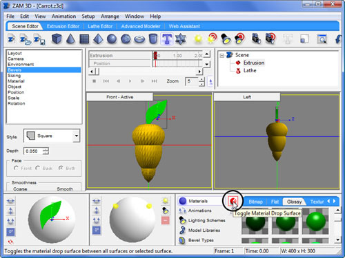
Let’s make our leaf a glossy, shiny green. Go to the Gallery Toolbar and click the icon between the word Materials and the tabs. Its ToolTip reads Toggle Material Drop Surface. If we don’t toggle it, we have to drop a material on each of the four sides of the leaf.
The icon is circled in Figure B.8.
Locate a nice glossy green; I used “ER – Glossy 21.” Drag it onto the leaf model in one of the viewports.
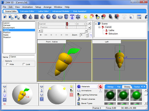
Hold down Shift and select both the leaf and the carrot. When they are both selected, you will see Group of 2 Objects appear in the Hierarchy Toolbar. On the left, just under the Properties Toolbar, change the name of the group to
Carrot.Now we can treat the two models as a single object. We’re going to tilt the carrot so that the animation will be more pronounced. In the Rotation Toolbar, click the icon labeled 0°, then select 30°. This means that we can rotate the selection only in 30° increments.
Click the icon just above 30°. Its ToolTip reads Lock Spin. This restricts the rotation to just the X,Y plane.
Click and drag the carrot in the Rotation Toolbar until it resembles Figure B.9.
Back in the Gallery Toolbar, select Animations.
Underneath the first tab, Common Spins, you will see a number of readymade spin animations. Click and drag the first one, Horizontal Left, onto the carrot in one of the viewports.
Examine the Animation Toolbar and you will see that timeline controls are now available. Click the play icon to preview the animation.
Now we are ready to move our animated 3D carrot into a WPF application! From the menu select File, Export Scene to XAML.
There are lots of options here. For simplicity, we’ll accept the default options. This will create a single, standalone XAML file that will begin playing our animation as soon as it loads.
Open the XAML file we just exported in a text editor, such as Notepad. You can now copy and paste the XAML directly into a Visual Studio project. Some of the namespace declarations are redundant, but it won’t hurt anything if you create a Button and paste this markup inside of it!