
7
–––––––––––––––––––––––
A Performance Analysis Methodology for MultiCore, Multithreaded Processors
Miao Ju, Hun Jung, and Hao Che
7.1 INTRODUCTION
As chip multiprocessors (CMPs) become the mainstream processor technology, challenges arise as to how to design and program CMPs to achieve the desired performance for applications of diverse nature. There are two scalability barriers that the existing CMP analysis approaches (e.g., simulation and benchmark testing) find difficult to overcome. The first barrier is the difficulty for the existing approaches to effectively analyze CMP performance as the number of cores and threads of execution becomes large. The second barrier is the difficulty for the existing approaches to perform comprehensive comparative studies of different architectures as CMPs proliferate. In addition to these barriers, how to analyze the performance of various possible design/programming choices during the initial CMP design/programming phase is particularly challenging, when the actual instruction-level program is not available.
To overcome the above scalability barriers, approaches that work at much coarser granularities (e.g., overlooking microarchitectural details) than the existing ones must be sought to keep up with the ever-growing design space. Such an approach should be able to characterize the general performance properties for a wide variety of CMP architectures and a large workload space at coarse granularity. Moreover, such an approach cannot assume the availability of the instruction-level programs as input for performance analysis. The aim is to narrow down the design space of interest at coarse granularity in the initial design/programming phase, in which an existing approach can work efficiently to further pin down the optimal points at finer granularities in a later design/programming phase. To this end, we believe that an overarching new approach, encompassing both existing and future design and workload spaces, should be sought. In this chapter, we discuss a new methodology in an attempt to achieve such a design objective.
The proposed methodology aims at exploring a large design space at coarse granularity. More specifically, it works at the thread level, overlooking instruction-level and microarchitectural details, except those having significant impact on thread-level performance, such as an instruction for memory access or instructions that cause serialization effects. The methodology works in a large design space, covering various processor organizations, pipelined/parallel core configurations, thread-scheduling disciplines, and memory access mechanisms. This methodology leads to the successful development of a queuing network modeling technique with closed-form solutions, making it possible to study the general performance properties of CMPs over a large design space. Moreover, it also leads to the development of a lightweight simulation tool (ST) with extremely low time and space complexities, also viable for large design space exploration. In this chapter, we introduce the methodology, the ST, and the modeling technique focusing on the following performance measures: throughput, delay, and loss. Other performance measures, such as power and memory consumptions, will be incorporated in the future. The results in this chapter are partially presented in References 1 and 2.
The rest of this chapter is organized as follows. Section 7.2 describes the methodology. Section 7.3 and 7.4 present the ST and the analytic modeling technique developed based on this methodology, respectively. Section 7.5 provides test results for the queuing modeling technique against the simulated ones. Section 7.6 discusses the related work. Finally, Section 7.7 presents the conclusions and future work.
7.2 METHODOLOGY
The main idea of our methodology is to capture only activities that have a major impact on the thread-level performance. In other words, the instruction level and microarchitectual details are overlooked unless they trigger events that may have significant effects at the thread level, such as an instruction for memory access that causes the thread to stall or instructions corresponding to a critical region that cause serialization effect at the thread level. Correspondingly, all the components including CPU, cache/memory, and interconnection network are modeled at a highly abstract level, overlooking microarchitectual details, just enough to capture the thread-level activities. For example, for a CPU running a coarse-grained thread-scheduling discipline and a memory with a FIFO queue, they are modeled simply as queuing servers running a coarse-grained thread-scheduling algorithm and FIFO discipline, respectively. The following sections describe, at the thread level, the modeling of the CMP organization, the workload, and the design space, separately. Since in the CMP family communication processors (CPs) are particularly difficult to model due to their workload dependence on packet arrival processes, which are stochastic in nature, in the rest of this chapter and without loss of generality, we discuss CMP in the context of CP. All we need to note is that, for a CP, program tasks mapped to a thread in a core, which determine the workload characteristics, come from packets, rather than a program or program tasks loaded in that core.
7.2.1 CMP Organization
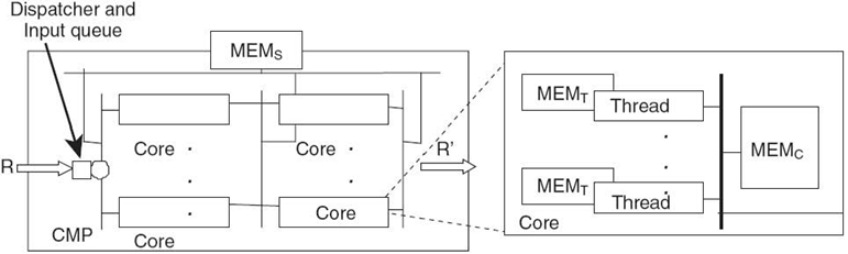
We consider a generic CP organization depicted in Figure. 7.1. This organization focuses on the characterization of multicore and multithread features common to most of the CMP architectures, leaving all other components being summarized in highly abstract forms. More specifically, in this organization, a CP is viewed generically as composed of a set of cores and a set of on-chip and/or off-chip supporting components, such as I/O interfaces, memory, level one and level two caches, special processing units, scratch pads, embedded general-purpose CPUs, and coprocessors. These supporting components may appear at three different levels, that is, the thread, core, and system (including core cluster) levels, collectively denoted as MEMT, MEMC, and MEMS, respectively. Each core may run more than one thread and the threads are scheduled based on a given thread-scheduling discipline.
Cores may be configured in parallel and/or multistage pipelining (a two-stage configuration is shown in Fig. 7.1), and there is a packet stream coming in from one side and going out through the other side. Packet processing tasks may be partitioned and mapped to different cores at different pipeline stages or different cores at a given stage. A dispatcher distributes the incoming packets to different core pipelines based on any given policies. Backlogged packets are temporarily stored in an input buffer. A small buffer may also present between any two consecutive pipeline stages to hold backlogged packets temporarily. Packet loss may occur when any of these buffers overflow.
Clearly, the above organization also applies to non-CP-based CMPs. The only difference is that, in this case, there is no packet arrival, or departure processes and tasks mapped to different cores are generated by one or multiple applications mapped to those cores. This chapter is concerned with the CP throughput, latency, and loss performance only, and the power and memory resource constraints are assumed to be met. This implies that we do not have to keep track of memory or program store resource availabilities or power budget.
7.2.2 Workload
At the core of our methodology is the modeling of the workload, defined as a mapping of program tasks to threads in different cores, known as code paths. For tasks mapped to a given thread, a piece of pseudocode for those tasks can be written. Then a unique branch from the root to a given leaf in the pseudocode is defined as a code path associated with that thread. A specific packet processing or instantiation of program execution is associated with a specific code path, or a sequence of events that the thread needs to execute to fulfill the tasks. For a CP, the program tasks mapped to a thread may be on and off, which is a function of the packet arrival process. Moreover, what code path a thread may need to handle in a given time period is dependent on the actual mixture of packets of different types arriving in that time period, each being associated with some distinct program tasks to be fulfilled, known as a mixture of code paths. For example, while an IP packet may be subject to the entire cycle of both layer 2 and layer 3 processing, resulting in a long code path, a packet carrying IS‒IS routing information is forwarded to the control plane immediately after it is identified at layer 2, which leads to a very short code path.
In this chapter, a code path is defined at the thread level, which is composed of a sequence of segments corresponding to different events that have a significant impact on the thread-level performance. For each segment, we are only concerned with the segment length in terms of the number of core cycles. It can be formally defined as follows:
Tk(Mk;m1, k, t1, k, τ1, k, ⋯, mMk, k, tMk, kτMk, k): Code path k with event mi, k occurred at the ti, k-th core clock cycle and with event duration τi, k, where k = 1,…, Kand i = 1, 2,…, Mk;K is the total number of code paths in the pseudocode; and Mk is the total number of events in the code path k.
A graphic representation of such a code path is given in Figure 7.2.
We note that a code path thus defined is simply a sequence of events with event interarrival times ti + 1, k − ti, k = τi, k for i = 1, 2,…, Mk − 1. The events mi, k ∈ CPU are represented by the white segments, and the corresponding τi, k is the number of core cycles the CPU spends on this thread in this segment. All other events are separated by the CPU events. For an event mi, k ∈ MEMT, MEMC, or MEMS, τi, k represents the unloaded resource-access latency. An event can be introduced to account for the serialization effect caused by, for example, a critical region. Hence, the length of the code path Tk, denoted as |Tk|, is the total duration of code path k handled by a thread in the absence of resource contention, that is, without waiting times due to contention with other threads for CPU, memory, and any other resource accesses. An event is defined as one that is expected to have a significant impact on the thread-level activities. Currently, we have defined the following four types of events:
(1) CPU events; (2) resource-access events, which may cause significant delay and thread-level interactions (i.e., context switching), that is, mi, k ∈ MEMT, MEMC, or MEMS; and (3) events that cause serialization effects, for example, a critical region. More types of events can be incorporated if they are expected to contribute significantly to the thread-level activities.
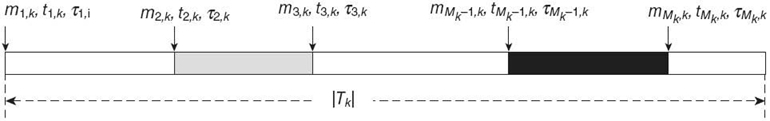
FIGURE 7.2. Tk(Mk;m1, k, t1, k, τ1, k, ⋯, mMk, k, tMk, kτMk, k).
7.2.3 Design Space
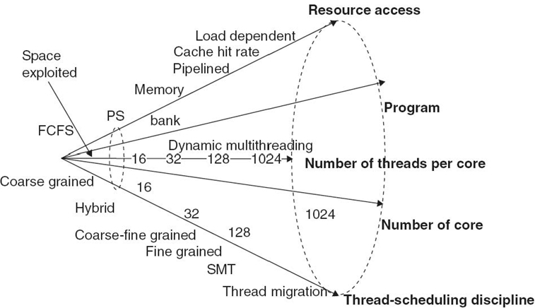
We want the design space to be as large as possible to encompass as many CMP architectures and workloads as possible. Figure 7.3 depicts such a design space. It is a five-dimensional space, including resource-access dimension, thread scheduling-discipline dimension, program dimension, number-of-thread-per-core dimension, and number-of-core dimension. Figure 7.3 also shows the part (i.e., the small cone on the left) that has been (incompletely) explored by the existing work using queuing network modeling techniques (see Section 7.6 for more details). Clearly, the existing work only covers a tiny part of the entire design space.
The thread scheduling-discipline dimension determines what CPU or core type is in use. The existing commercial processors use fine-grained, coarse-grained, simultaneous multithreading (SMT), and hybrid coarse-and-fine-grained thread-scheduling disciplines. Some systems may also allow a thread to be migrated from one core to another.
The resource-access dimension determines the thread access mechanisms to CMP resources other than CPU. It may include memory, cache, interconnection network, and even a critical region. The typical resource-access mechanisms include first come, first served (FCFS), process sharing (parallel access), parallel resources (e.g., memory bank), and pipelined access. For cache access, a cache hit model may have to be incorporated, which may be load dependent. The program dimension includes all possible programs. This dimension is mapped to a workload space, involving all possible code path mixtures, for a given type of processor organization. The number-of-core and number-of-thread-per-core dimensions determine the size of the CMP in terms of the numbers of cores and threads. The number-of-thread-per-core dimension also needs to deal with dynamic multithreading, where the number of threads used for a program task may change over time due to on-and-off packet arrivals or the variation of the level of parallelism in a program.
In summary, this section described a methodology that provides a coarse-granular, thread-level view of a CMP in general and a CP in particular in terms of its organization and design space. Based on this methodology, the following two sections demonstrate how an analytic modeling technique and a framework for fast program-task-to-core mapping can be developed to allow much of the design space in Figure.7.3. to be explored.
7.3 SIMULATION TOOL (ST)
7.3.1 Basic Idea
Our ST [2] focuses on three performance measures: throughput, delay, and loss. All three measures can be obtained at runtime as long as the latency Lk for a packet with code path k in each core can be simulated, which can be expressed as
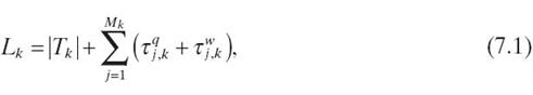
where τqj, k is the thread queuing time for the event mj, k and τwj, k is the waiting time in the ready state after the event mj, k finishes. For an event mj, k ∈ MEMT, MEMC, or MEMS, τi, k, which contributes to |Tk| (see Fig. 7.4), is dependent on the nature of mj, k access (number of memory reads or writes) and the access speed (bus speed and memory speed), which is assumed to be provided by the user as a plug-in.τqj, k and τwj, k are dominated by multithreading effects, dependent on the thread scheduling and queuing mechanism for resource mj, k access, which is the core parameter to be simulated at runtime.
Hence, for throughput, delay, and loss performance analysis, all that is needed from the user is a set of plug-ins that estimate τj, k for mj, k ∈MEMT, MEMC, or MEMS (note that τj, k for an event corresponding to a critical region can be estimated from the pseudocode itself). Note that, although modeling CMP-specific features in general is a nontrivial task, it should not be difficult to come up with empirical memory access latency models, for example, in the form of charts or tables for a given CMP. For example, by loading a given memory with different types of requests and measuring the corresponding unloaded latencies using a cycle-accurate simulator or test board, one can build empirical charts or tables offline to be used to quickly estimate τj, k at runtime. There is no need to emulate the microscopic process for memory access at runtime, saving significant amounts of simulation time. As demonstrated in Reference 2, with the unloaded memory access latencies provided by Intel, as well as a memory access waiting time estimated based on a simple FIFO queuing model (QM), our ST accurately characterizes IXP1200/2400 performance without further information about IXP1200/2400-specific features.
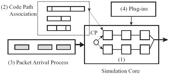
FIGURE 7.4. Proposed simulation model.
7.3.2 Simulation Model
With the above preparation, we now describe our simulation model, which focuses on emulating common features pertaining to all CMP architectures, including core topology, multithreading, code path, code path mixtures, and packet arrival processes, with a limited number of plug-ins to account for CMP-specific features. The plug-ins are predeveloped and plugged into the simulation model. Figure.7.4. gives a logic diagram for the proposed simulation model, which is composed of four major components: (1) a simulation core based on the generic CP organization described in Figure. 7.1, (2) code path association with a packet in a core, (3) a packet arrival process, and (4) a set of plug-ins to the simulation core.
Based on the generic CP architecture in Figure. 7.1, the simulation model focuses on emulating multithreaded cores, which can be configured in any pipeline/parallel topology. Each core is modeled at a highly abstract level, running any number of threads based on a given thread-scheduling discipline. No further details of the core are modeled. A thread in a core that receives a packet will be assigned a code path. The way to assign code paths to threads in a core determines the mixture of code paths in that core. The packet arrival process can be generated from real traces (which also determine the code path mixture in each core), stochastic models, or deterministic models. Traditionally, the code path assignment and packet arrival process generation are not part of the ST design but are user-provided inputs. Since all four components can be designed independent of one another, the design of components (1) and (4) combined constitutes a fast performance analysis tool in the traditional sense. In other words, as in traditional approaches, our tool allows any user-provided packet arrival processes and/or mixtures of code paths to be simulated. In Reference 2, we also designed components (2) and (3) such that for any given program-task-to-core mapping, the tool can quickly return the maximal line rate a CP can sustain. However, due to the page limitation, here we shall not discuss the design of these two components. The ST is event driven, and it processes a linked list of events corresponding to the segment boundaries in the execution sequence rather than instruction by instruction. A code path generally involves only a few to a few dozen events, which makes the tool extremely fast (see Section 7.5 for case studies). Moreover, since the next event is generally triggered by the execution of a current event, the linked list can be kept extremely small, consuming a negligible amount of memory resource. As a result, the ST is lightweight and fast.
7.4 ANALYTIC MODELING TECHNIQUE
7.4.1 General Model
As explained in detail in Reference 3, based on the proposed methodology, any types of CMPs with Ml active threads in the lth core (for l = 1,…, Nc), Ncl components associated with the lth core (including shared resources), and any long-run workloads can be generally modeled as a closed queuing network with Nc job classes and Ml jobs in the lth class, Ncl queuing servers of various service types in terms of queue scheduling disciplines, and a workload space (μil, pijl) for job class l, spanned by various possible combinations of service time distributions μil and routing probabilities pijl (note that the subscripts i and j are indices of the components associated with the l th core). The central task is then to develop mathematical techniques to analytically solve this closed queuing network model. The solution should be able to account for as many service types and as large a workload space as possible, aiming at covering a wide range of CMP architectures.
7.4.2 Design Space Coverage
The queuing network modeling techniques at our disposal limit the size of the design space to one that must be mathematically tractable. This makes the coverage of the design space in Figure.7.3. a challenge. In this section, we discuss our solutions in meeting the challenge.
7.4.2.1 Memory/Interconnect Network and Thread Scheduling-Discipline Dimensions Without resorting to any approximation techniques, the existing queuing network modeling techniques will allow both of these dimensions to be largely explored analytically. Any instance in either of these two dimensions can be approximately modeled using a queuing server model that has local balance equations (i.e., it leads to queuing network solutions of product form or closed form). More specifically, Table 7.1 shows how individual instances in these two dimensions can be modeled by three QMs with local balance equations (according to the BCMP theorem [4]), including M/G/∞, M/M/mFCFS (including M/M/1), and M/G/1PS (processor sharing). Note that memory banks should be modeled as separate queuing servers and, hence, are not listed in this table. Also note that for all the multi-thread-scheduling disciplines except the hybrid-fine-and-coarse-grained one (to be explained below) in Table 7.1, the service time distribution of a QM models the time distribution for a thread to be serviced at the corresponding queuing server. With these in mind, the following explains the rationales behind the mappings in Table 7.1:
- SMT. It allows multiple issues in one clock cycle from independent threads, creating multiple virtual CPUs. If the number of threads in use is no greater than the number of issues in one clock cycle, the CPU can be approximately modeled as an M/G/∞ queue, mimicking multiple CPUs handling all the threads in parallel; otherwise, it can be approximately modeled as an M/M/m queue, that is, not enough virtual CPUs to handle all the threads, and some may have to be queued.
TABLE 7.1. Component Modeling Using Queuing Models with Local Balance Equations
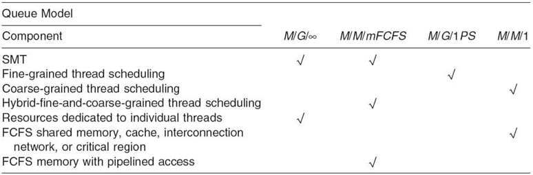
- Fine-Grained Thread-Scheduling Discipline. All the threads that access the CPU resource will share the CPU resource at the finest granularity, that is, one instruction per thread in a round-robin fashion. This discipline can be approximately modeled as an M/G/1PS queue; that is, all the threads share equal amounts of the total CPU resource in parallel.
- Coarse-Grained Thread-Scheduling Discipline. All the threads that access the CPU resource will be serviced in a round-robin fashion and the context is switched only when the thread is stalled, waiting for the return of other resource accesses. This can be approximately modeled as an FCFS queue, for example, an M/M/1 queue.
- Hybrid-Fine-and-Coarse-Grained Thread-Scheduling Discipline.It allows up to a given number of threads, say, m, to be processed in a fine-grained fashion and the rest to be queued in an FCFS queue. This can be modeled as an M/M/m FCFS queue. In this QM, the average service time for each thread being serviced is m times longer than the service time if only one thread were being serviced, mimicking fine-grained PS effect.
- Resources Dedicated to Individual Threads. Such resources can be collectively modeled as a single M/G/∞ queue; that is, there is no contention among different threads accessing these resources.
- FCFS Shared Memory, Cache, Interconnect Network, or Critical Region.This kind of resource can be modeled as an M/M/1 queue.
- FCFS Memory with Parallel Access. Memory banks can be accessed in parallel. It can be modeled as an M/M/m FCFS queue, with up to the number-of-bank worth of memory accesses serviced in parallel and the rest queued in an FCFS queue.
- FCFS Memory with Pipelined Access. Same as above. The pipeline depth determines how many threads can be serviced simultaneous in the M/M/m FCFS queue.
We note that the memory/interconnection-network dimension also includes load-dependent cache hit rate. The cache hit probability (i.e., the routing probability to move back to the CPU) is generally load dependent in the sense that it may either be positively or negatively correlated with the number of threads in use due to temporal locality and cache resource contention. These effects can be accounted for in our framework without approximation by means of the existing load-dependent routing techniques (e.g., see References 5). We also note that the thread scheduling-discipline dimension includes thread migration. The thread migration allows a thread to be migrated from one core to another for, for example, load balancing purpose. This effect can be accounted for without approximation by allowing jobs to have nonzero probabilities to switch from one class to another [6, 7]. More capabilities may be identified and included in these two dimensions as long as they are mathematically tractable.
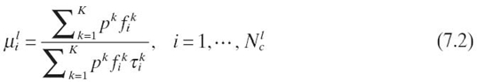
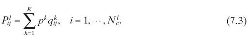
7.4.2.2 Program Dimension In principle, this dimension can be fully explored through a thorough study of the workload space, characterized by the service time distributions and routing probabilities, that is, a collection of ({μi}, {pij})'s. However, for the solvable queuing server models in Table 7.1, such as M/M/m and M/M/1 queues, the service time distribution μi is a given, that is, exponential distribution. Since the exponential distribution is characterized by only a single parameter, that is, the mean service time ti, it can only capture the first-order statistics of the code path segments corresponding to that server, hence providing a first-order approximation of the program dimension or workload space. Although our future research will explore more sophisticated QMs in an attempt to overcome this limitation, we expect that the first-order approximation could actually provide good performance data due to the well-known robustness property [6], which states that for closed queuing networks, the system performance is insensitive to the service time distributions. To calculate ({μi}, {pij }), we first define pk, the probability that an incoming packet is associated with code path k (for k = 1, 2,…, K). In other words, pk defines a code path mixture. We further define τik, fik, and qijk as the average service time at queuing server i, the frequency to access queuing server i, and the probability to access queuing server j upon exiting queuing server i, respectively, for a thread handling code path k. These statistic parameters are collectable from the pseudo-code. Then, the average service rates and routing probabilities for a given job class can be written as Here, a job class is defined as threads that follow these same statistics. In general, all the threads that belong to the same core form a job class.
and
7.4.2.3 Number-of-Core and Number-of-Thread Dimensions First, we note that the number-of-thread dimension should allow dynamic multithreading, meaning that at different program execution stages, the number of active threads may vary. In Section 7.5, we propose a possible solution, which will be further studied in the future. Second, we need to address the scalability issues in calculating the generation functions as the numbers of cores and threads increase. We consider a general closed queuing network modeling an N-core (or core cluster) system with P shared resources. We want to be able to get closed-form generation function G for such closed queuing networks, from which any performance measures can be derived. As long as all the queuing servers in the system have local balance equations (e.g., following the queuing server models in Table 7.1), the generation function or normalization function can be generally written as where fi (mik) is a function corresponding to the probability that there are mik threads currently in core i (for i = 1,…, N, where N is the number of cores) for thread class k (for k = 1,…, N; i.e., the threads from each core form a class), fi(mj1,…, mjN ) is a function corresponding to the probability that there are mj1 threads of class one, mj2 threads of class two, and so on, in queuing server j (for j = 1,…, P), and Mi is the total number of threads belonging to core i (for i = 1,…, N). fi(x)'s take different forms for different core organizations, in terms of, for example, CPU, cache, and local memory of different types from the resource-access dimension and thread scheduling-discipline dimension of the design space. On one hand, we note that G is defined on the entire design space (with the first-order approximation of the program dimension or workload space). Understanding the general properties of G over this space will allow the properties of individual points in the design space to be understood. On the other hand, we also note that the number-of-core and number-of-thread-per-core dimensions create scalability barriers that prevent us from being able to effectively calculate G. This is because the computational complexity for G is O(NSMN+ P), where M is the average number of threads per core and NS is the average number of queuing servers per core. Our experiments on an Intel Core Duo, T2400, 1.83-GHz processor showed that for NS = M = 2 and P = 1, it takes about 24 hours to compute the generation function for a 20-core system. Clearly, it is computationally too expensive to cover the entire number-of-core and number-of-thread dimensions. In the following, we develop an iterative procedure to overcome this scalability barrier.
7.4.2.4 An Iterative Procedure The difficulty to calculate G(x) lies in the fact that different cores interact with one another through shared resources. A key intuition is that the effect on each core due to resource sharing with other cores would become more and more dependent on the first-order statistics (i.e., mean values) and less sensitive to the higher-order statistics (e.g., variances) or the actual distributions as the number of cores sharing the resources increases (reminiscent of the law of large numbers and the central limit theorem in statistics and the mean field theory in physics, although actual formal analysis could be difficult). With this observation in mind, we were able to design an iterative procedure to decouple the interactions among cores so that the performance of each core can be evaluated quickly as if it were a stand-alone core.
Assume there are N cores sharing a common FIFO memory. Initially, we calculate the sojourn time Ti(0) and throughput λi(0) for single-core system i consisting of a core and the common memory (for i = 1,…, N). Then, the initial mean sojourn time for all the cores, T*(1), is calculated based on the following formula:
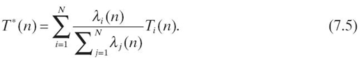
Then, we enter an iteration loop as shown in Figure.7.5. At the nth iteration, first the average sojourn time for the common memory, Tm(n), is calculated based on a two-server queuing network (on the left of Fig. 7.5), including a queuing server for the common memory and an M/M/∞ queuing server characterized by the mean service time T*(n). There are a total of![]() mi threads circulating in this network, where mi is the number of active threads in core i. In other words, we approximate the aggregate effect of all the threads from all the cores on the common memory using a single M/M/∞ queuing server with the mean service time T*(n). Then, we test if |Tm(n)−TM(n−1)| ≤ ε holds, for a predefined small value ε. If it does, exit the loop and finish; otherwise, do the following. The sojourn time Ti(n) and throughput λi(n) for core i (for i = 1,…, N) are updated based on the closed queuing network on the right of Figure.7.5. This time, the effects of other cores on core i are accounted for using a single M/M/∞ server with the mean service timeTm(n). There are mi threads circulating in this network. Finally, T*(n) is updated before entering the next iteration. Note that both steps involve only queuing network models that have closed-form solutions, which make each iteration loop extremely fast.
mi threads circulating in this network, where mi is the number of active threads in core i. In other words, we approximate the aggregate effect of all the threads from all the cores on the common memory using a single M/M/∞ queuing server with the mean service time T*(n). Then, we test if |Tm(n)−TM(n−1)| ≤ ε holds, for a predefined small value ε. If it does, exit the loop and finish; otherwise, do the following. The sojourn time Ti(n) and throughput λi(n) for core i (for i = 1,…, N) are updated based on the closed queuing network on the right of Figure.7.5. This time, the effects of other cores on core i are accounted for using a single M/M/∞ server with the mean service timeTm(n). There are mi threads circulating in this network. Finally, T*(n) is updated before entering the next iteration. Note that both steps involve only queuing network models that have closed-form solutions, which make each iteration loop extremely fast.
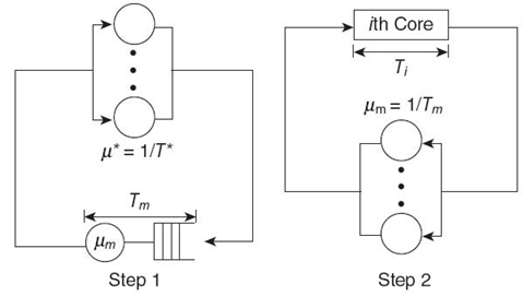
FIGURE 7.5. Iterative procedure.
7.5 TESTING
The testing results for the ST against the cycle-accurate simulation were presented in Reference 2. The performance data for the ST were shown to be within 5% of the cycle-accurate simulation data for applications run on IXP1200 and IXP2400 network processors. In this section, we test the accuracy of the queuing modeling technique for CMPs with 1000 cores and up to several thousands of threads. The results are compared against those obtained by our ST. Note that our ST is the only existing tool that can scale to CMPs in a large design space involving thousands of cores and threads, and various component models.
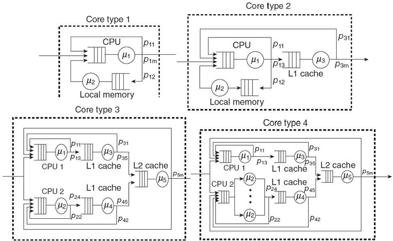
We consider a CMP with 1000 cores and core clusters sharing a common FIFO memory. There are two types of cores (i.e., core type 1 with 6 active threads and core type 2 with 9 active threads) and two core clusters (i.e., core type 3 with 8 active threads and core type 4 with 10 active threads), 250 each, as given in Figure.7.6. Core type 1 may model a CPU with a cache (with hit probability p11, overlooking queuing effects), a local memory (with routing probability p12), and routing probability p1m to access the common memory. Core type 2 involves an additional server, modeling, for example, an L2 cache. Core type 3 models a two-core cluster with dedicated L1 and L2 caches and local shared memory or L3 cache. Core type 4 differs from core type 3 just in one of its cores, which runs SMT CPU instead of a coarse-grained one (i.e., an M/M/m queue and all the rest are M/M/1 queues).
The parameter settings for each type of core are given as follows:
- Type 1-group1 (single class):
(μ1, μ2) = (0.05, 0.03)
(p11, p12, p1m) = (0.25, 0.7, 0.05)
m1 = 6 - Type 2-group2 (single class):
(μ1, μ2, μ3) = (0.2, 0.1, 0.1)
(p11, p12, p13,
p31, p3m) = (0.3, 0.6, 0.1, 0.95, 0.05)
m1 = 9 - Type 3-group3 (multiclass):
(μ1, μ2, μ3, μ4, μ4) = (0.2, 0.2, 0.2, 0.2, 0.1)
(p11, p13, p22, p23, p31, p35 (p42, p45, p5m)
= (0.2, 0.8, 0.2, 0.8, 0.9, 0.1, 0.9, 0.1, 0.02)
(m1, m2) = (8, 8) - Type 4-group4 (multiclass):
(μ1, μ2, μ3, μ4, μ4) = (0.2, 0.1, 0.15, 0.15, 0.1)
(p11, p13, p22, p23, p31, p35(p42, p45, p5m)
= (0.2, 0.8, 0.2, 0.8, 0.9, 0.1, 0.9, 0.1, 0.02)
(m1, m2) = (10, 10)
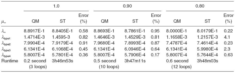
For the ST, simulation stops when all nodes in all cores execute at least 106 events. For the iteration procedure, ε is set at 0.1% of Tm(n). The test results for the proposed QM and ST at three different common memory service rates are listed in Tables 7.2‒7.4. Both QM and ST are done on an Intel Pentium 4 computer. The computation and simulation times are also listed.
In each table, there are three columns with different common memory service rates representing three distinctive cases. In the first case, the memory capacity is larger than the aggregate capacity of all the cores (i.e., the memory in underloaded condition). In the second case, their capacities are almost the same. In the last case, the aggregate capacity of all the cores is larger than the memory capacity (i.e., the shared memory is a potential bottleneck resource). Each column has three subcolumns, with the first subcolumn showing the results from QM and the second from ST and the last the difference between them. Table 7.2 gives the results for the above parameter settings. Table 7.3 and Table 7.4 give the results with some parameter changes (see the parameter changes at the top of each table).
It turns out that our iterative procedure is highly accurate and fast. For the cases in Table 7.2 and Table 7.4, it takes less than 12 iterations to get the results. For the case in Table 7.3, the number of iterations increases up to 26. For all the cases studied, the technique is three orders of magnitude faster than ST, finishing within a few seconds. This allows a large design space (or parameter space) to be scanned numerically. Moreover, for all the cases, the results are consistently within 5% of the simulation results.
One can further reduce the time complexity by running the iterative procedure only once for a given set of parameters to get effective Tm. Then, study the performance for any target core in a workload parameter range based on the closed queuing network in Figure.7.5. (the one on the right) with Tm fixed. One can expect that changing parameters for just one core out of 1000 cores should not significantly affect Tm as is the case in Table 7.4 compared to Table 7.3. This approximation further reduces the time complexity by another two orders of magnitude.
As one can see, with the proposed analytic modeling technique, the closed queuing network models can now be effectively used to explore the design space in Figure.7.3. A user of our technique may start with a coarse-grained scan of the space first, which will allow the user to identify areas of further interests in the space. Then, perform a finer-grained scan of the areas of interest.
TABLE 7.2. All and Each Type's Throughputs with Various Common Memory Service Times
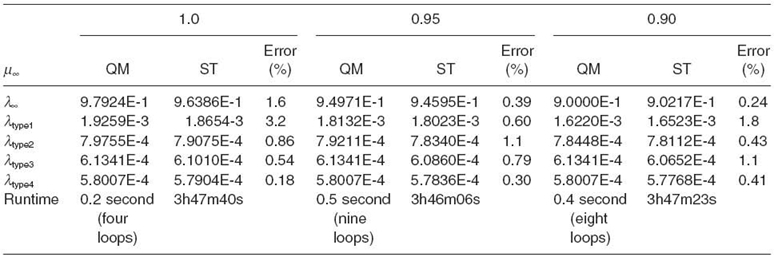
TABLE 7.3. Changes in All Cores in Group 1 (µ = 0.05 → 0.03, m1 = 6 → 8)
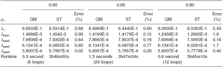
TABLE 7.4. A Change in One Target Core in Group 4 (L2 Hit Rate 98% → 90%)
7.6 RELATED WORK
Since this chapter is concerned with both analytical queuing network modeling and simulation, we review the existing results on both separately.
In terms of queuing network modeling, since Jackson's seminal work [8] in 1963 on queuing networks of product form, a wealth of results on the extension of his work has been obtained for both closed and open queuing networks. Notable results include the extensions from M/M/1 FCFS to last come, first served (LCFS) preemptive resume, PS, and IS queuing disciplines, multiple job classes (or chains) and class migrations, load-dependent routing and service times, and exact solution techniques such as convolution and mean value analysis (MVA), and approximate solution techniques for queuing networks with or without product form. Sophisticated queuing network modeling tools were also developed, making queuing modeling and analysis much easier. These results are well documented in standard textbooks, tutorials, and research papers (e.g., see References 6, 7, 9, and 10). As a result, in the past few decades, queuing networks were widely adopted in modeling computer systems and networks (e.g., see References 1 and 11‒14). However, very few analytical results are available for multicore processor analysis. In Reference 15, an MVA of a multithreaded multicore processor is performed. The performance results reveal that there is a performance valley to be avoided as the number of threads increases, a phenomenon also found earlier in multiprocessor systems studied based on queuing network models [3]. Markovian models are employed in Reference 16 to model a cache memory subsystem with multithreading. However, to the best of our knowledge, the only work that attempts to model multithreaded multicore using the queuing network model is given in Reference 17. But since only one job class (or chain) is used, the threads belonging to different cores cannot be explicitly identified and separated in the model, and hence multicore effects are not fully accounted for.
Most relevant to our work is the work in Reference 13. In this work, a multiprocessor system with distributed shared memory is modeled using a closed queuing network model. Each computing subsystem is modeled as composed of three M/M/1 servers and a finite number of jobs of a given class. The three servers represent a multithreaded CPU with coarse-grained thread-scheduling discipline, an FCFS memory, and an FCFS entry point to a crossbar network connecting to other computing subsystems. The jobs belonging to the same class or subsystem represent the threads in that subsystem. The jobs of a given class have given probabilities to access local and remote memory resources. This closed queuing network model has a product-form solution.
The above existing application of queuing results to the multithreaded multicore and multiprocessor systems is preliminary (i.e., within the small cone on the left in Fig. 7.3.) The only queuing discipline studied is the FCFS queue, which characterizes the coarse-grained thread-scheduling discipline at a CPU and FCFS queuing discipline for memory or interconnection network. No framework has ever been proposed that can cover the design space in Figure 7.3 and that allows system classes to be analyzed over the entire space. In terms of simulation, there are a vast number of processor STs available [18‒33] (e.g., cycle accurate, allowing detailed timing analysis, and providing primitives for flexible component modeling). Particularly relevant to our work are the CP analysis tools (e.g., see References 18, 22, 24‒26, 28, and 30‒33).
Most CP simulation software (e.g., see References 18, 24, 25, and 31) aims at providing rich features to allow detailed statistical or per-packet analysis, which is useful for program fine tuning, rather than fast CP performance testing. Even for the most lightweight NP simulator described in Reference 31, it is reported that to simulate 1 second of hardware execution, it takes 1 hour on a Pentium III 733 PC. Moreover, it assumes the availability of the executable program or microcode as input for the simulation. On the other hand, the algorithms for data path functions to CP core topology mapping (e.g., see References 30 and 32‒34) are generally fast, but at the expense of having to overlook many essential processing details that may have an impact on the overall system performance. To make the problem tractable, a common technique used in these approaches is to partition the data path functions into tasks, and each task is then associated with one or multiple known resource demand metrics, for example, the core latency and program size. Then an optimization problem under the demand constraints is formulated and solved to find a feasible/optimal mapping of those tasks to a pipelined/parallel core topology. Since the actual resource demand metrics for each task are, in general, complex functions of mapping itself and are a strong function of the number of threads and thread scheduling discipline in use at each core, these approaches cannot provide mappings with high accuracy. Although the approach in Reference 30 accounts for certain multithreading effects, it only works for a single memory access and under a coarse-grained scheduling discipline.
7.7 CONCLUSIONS AND FUTURE WORK
In this chapter, we proposed a methodology for performance analysis of many-core systems in a large design space. The novelty of the methodology lies in the fact that it works at the thread level and it studies the general properties of system classes over the entire space. Hence, it is free of scalability issues.
The framework can cover the entire design space in Figure 7.3 except the dynamics of multithreading. In the future, we plan to explore the following possible solution. We plan to use a set of ancillary thread classes with different delay loops to join and leave the queuing network modeling a core. It can be easily shown that with n thread classes and 2i− 1 threads in the i th class for i = 1,…, n, any number of threads in the range [1, 2n + 1 − 1] can be generated in the core. For example, with n = 4, any number of threads in the range of [1, 31] can be generated. The first thread class has only one thread in it. This thread class runs in the queuing network modeling the core. The rest n‒1 thread classes run in the delay loops. It can also be shown that by properly setting the delay value for each delay loop, the proposed model can match any distribution of parallelism (i.e., with probability Pk that k threads are presented in the core). The queuing network with these delay loops has a closed form solution.
REFERENCES
[1] D. Ghosal and L. Bhuyan, “Performance evaluation of a dataflow architecture,” IEEE Transactions on Computers, 39(5): 615‒627, 1990.
[2] H. Jung, M. Ju, H. Che, and Z. Wang, A Fast Performance Analysis Tool for Multicore, Multithreaded Communication Processors. December 2008.
[3] A. Agarwal, “Performance tradeoffs in multithreaded processors,” IEEE Transactions on Parallel and Distributed Systems, 3(5): 525‒539, 1992.
[4] F. Baskett, K.M. Chandy, R.R. Muntz, and F. Palacios, “Open, closed, and mixed networks of queues with different classes of customers,” Journal of the ACM, 22(2): 248‒260, 1975.
[5] D. Towsley, “Queuing network models with state-dependent routing,” Journal of the ACM, 27(2): 323‒337, 1980.
[6] G. Bolch, S. Greiner, H. de Meer, and K.S. Trivedi, Queueing Networks and Markov Chains, 2nd ed. John Wiley, 2006.
[7] ITU-D Study Group 2, Teletraffic Engineering, 2002.
[8] J.R. Jackson, “Jobshop-like queuing systems,” Management Science, 10: 131‒142, 1963.
[9] I.F. Akyildiz and A. Sieber, “Approximate analysis of load dependent general queuing networks,”IEEE Transactions on Software Engineering, 14(11): 1537‒1545, 1988.
[10] A. Thomasian and P.F. Bay, “Integrated performance models for distributed processing in computer communication networks,” IEEE Transactions on Software Engineering, SE-11(10): 1203‒1216, 1985.
[11] P.P. Chen, “Queuing network model of interactive computing systems,” in Proc. of the IEEE, June 1975.
[12] N. Lopez-Benitez and K.S. Trivedi, “Multiprocessor performability analysis,”IEEE Transactions on Reliability, 42(4): 579‒587, 1993.
[13] S.S. Nemawarkar, R. Govindarajan, G.R. Gao, and V.K. Agarwal, “Analysis of multi-threaded multiprocessors with distributed shared memory,” inProceedings of the 5th IEEE Symposium on Parallel and Distributed Processing, December 1993.
[14] B. Smilauer, “General model for memory interference in multiprocessors and meanvalue analysis,” IEEE Transactions on Computer, 34(8): 744‒751, 1985.
[15] Z. Guz, E. Bolotin, I. Keidar, A. Kolodny, A. Mendelson, and U.C. Weiser, “Many-corevs. many-tthread machines,” IEEE Computer Architecture Letter, 8(1): 25‒28, 2009.
[16] X.E. Chen and T.M. Aamodt, “A first-order fine-grained multithreaded throughputmodel,” in Proceedings of the 15th IEEE International Symposium on High-Performance Computer Architecture (HPCA), February 2009.
[17] V. Bhaskar, “A closed queuing network model with multiple servers for multithreadedarchitecture,” Journal of Computer Communications, 31(14): 3078‒3089, 2008.
[18] Advanced Software Development Tools for Intel IXP2xxx Network Processors, 2003. Intel White Paper.
[19] T. Austin, E. Larson, and D. Ernst, “SimpleScalar: An infrastructure for computer system modeling,” IEEE Computer, 35(2): 59‒67, 2002.
[20] J. Emer, “Asim: A performance model framework,” IEEE Computer, 35(2): 68‒72, 2002.
[21] Z. Huang, J.P.M. Voeten, and B.D. Theelen, “Modeling and simulation of a packet switchsystem using POOSL,” in Proceedings of the PROGRESS Workshop, October 2002.
[22] E. Johnson and A. Kunze, IXP 1200 Programming. Intel Press, 2002.
[23] E. Kohler, R. Morris, B. Chen, J. Janotti, and M.F. Kaashoek, “The click modular router,” ACM Transactions on Computer Systems, 18(3): 263‒297, 2000.
[24] Y. Luo, J. Yang, L.N. Bhuyan, and L. Zhao, “NePSim: A network processor simulatorwith a power evaluation framework,” IEEE Micro, Special Issue on Network Processors for Future High-End Systems and Applications, 24(5): 34‒44, Sep 2004.
[25] P. Paulin, C. Pilkington, and E. Bensoudane, “StepNP: A system-level exploration plat-form for network processors,” IEEE Design and Test of Computers, 19(6): 17‒26, 2002.
[26] R. Ramaswamy, N. Weng, and T. Wolf, “Analysis of network processing workloads,” in Proceedings of the IEEE International Symposium on Performance Analysis of Systems and Software (ISPASS), Mar 2005.
[27] M. Rosenblum, E. Bugnion, S. Devine, and S.A. Herrod, “Using the SimOS machine simulator to study complex computer systems,” Modeling and Computer Simulations, 7(1): 78‒103, 1997.
[28] L. Thiele, S. Chakraborty, M. Gries, and S. Kiinzli, “Design space exploration of networkprocessor architectures,” in Network Processor Design: Issues and Practices (P. Crowley, M. Franklin, H. Hadimioglu, and P. Onufryk, eds.), p. 1. Burlington, MA: Morgan Kaufmann Publishers, 2002.
[29] M. Vachharajani, N. Vachharajani, D. Penry, J. Blome, and D. August, “The LibertySimulation Environment, version 1.0,” Performance Evaluation Review: Special Issue on Tools for Architecture Research, 31, 2004.
[30] N. Weng and T. Wolf, “Pipelining vs multiprocessors? Choosing the right network processor system topology,” in Proceedings of the Advanced Networking and Communications Hardware Workshop (ANCHOR 2004) in conjunction with ISCA 2004, June 2004.
[31] W. Xu and L. Peterson, “Support for software performance tuning on network processors,” IEEE Network, 17(4): 40‒45, 2003.
[32] L. Yang, T. Gohad, P. Ghosh, D. Sinha, A. Sen, and A. Richa, “Resource mapping and scheduling for heterogeneous network processor systems,” in Proceedings of the Symposium on Architecture for Networking and Communications Systems, 2005.
[33] J. Yao, Y. Luo, L. Bhuyan, and R. Iyer, “Optimal network processor topologies for efficient packet processing,” in Proceedings of IEEE GLOBECOM, November 2005.
[34] H. Che, C. Kumar, and B. Menasinahal, “Fundamental network processor performance bounds,” in Proceedings of IEEE NCA, July 2005.