]>
Chapter 12
Application of Unmanned Aerial Vehicles in Wireless Networks
Mobile Edge Computing and Caching
CONTENTS
12.3 Description of Caching and Mobile Edge Computing
12.3.2 Overview of Mobile Edge Computing
12.4 Layering of UAV-Based MEC Architecture
12.4.1 Explanation of the Layers
12.5.1 Mathematical Model of NOMA
12.5.4.2 Local Computing Model
12.1 Introduction
To provide better service for human beings, Unmanned Aerial Vehicles (UAVs), also called drones, are applied in fifth-generation (5G) mobile networks for their versatile functionality. With the use of Mobile Edge Computing (MEC) in the UAVs, data transfer is improved and communication is made more efficient. UAVs work as flying base station (BS) because a static BS cannot be effectively used to serve the mobile users (MUs) when they relocate themselves from the designated coverage range of the BS. In addition, while a MU travels to a new cell, its solicited content might be unavailable at the new BS which leaves the user’s request unattended. In such cases, to serve the MU, multiple BSs might be required which will not be efficient. Therefore, we have chosen UAVs to be operated as flying BSs as they can follow the mobility pattern of the users, thereby rightfully serving them. As a result of their high altitude and flexibility, they can set up reliable communication network with the users by diminishing the blockage effect [1].
With UAV as a BS, MEC has been an important part in the 5G network and Internet of Things (IoT). The role of MEC is to provide cloud-like services to its MUs at the network edge. This will in turn allow applications in mobile devices and services from the edge network to function with reduced latency as well as with improved reliability of their communication [2]. Thus, MEC is also responsible for improving the Quality-of-Services (QoS), as well as the Quality-of-Experience (QoE) of the MUs via high-speed communication. It is also implementing the edge computing layer within the UAV-based MEC architecture to further facilitate a traffic free, secure network for real-time applications and machine intelligence [3], along with optimizing computational offloading and resource allocation [4].
A UAV-equipped MEC system which is powered wirelessly has multiple advantages in wireless communication. With effective deployment and operation, drones contribute to a dependable, cost-efficient connection to desired locations. UAV as flying BS (UAV-BS) not only have the potential to modify their altitude as per requirement but are also capable of avoiding obstacles and establishing improved Line-of-Sight (LOS) communications. Apart from mobility and flexibility, they provide enhanced capacity to areas with greater traffic and can be used to deliver coverage to remote areas which do not have proper network access without the need of building an expensive cellular infrastructure [5]. UAVs also act as an energy transmitter which can be used to supply energy to the ground MUs, thereby improving power levels and energy consumption [4]. In addition to UAV’s benefits, MEC can further improve the communication by hosting software and applications that can access user traffic and radio network information to help them modify their services for an enhanced user experience [6]. Furthermore, it has the added benefit of not requiring any new consumer technology to enjoy its services [7]. Besides being able to ensure quick responses [8], it has other practical uses which include Augmented Reality (AR), Virtual Reality (VR), autonomous cars and a lot more which will be further explained in [7, 8].
12.1.1 Chapter Roadmap
Our chapter’s contributions can be written in the following manner:
To overcome the problems of low-latency and reliability of communication system, the UAV-BS provides better service to the MUs. We will also implement MEC into the system to further improve the efficiency of communication.
To provide the advantages and disadvantages of executing MEC and caching at the UAV-BS and explain the different layers of the MEC system and their role in communication.
To use NOMA technique in our proposed model, we derive mathematical expression of data rate, transmission delay, time consumption and energy consumption.
Simulations are carried out at different signal-to-noise ratio (SNR) for both uplink and downlink communication to compare the relationships with data rate, transmission delay and energy consumption.
The rest of our chapter is written as follows. Literature review is given in Section 12.2. Section 12.3 is comprised of the description, advantages and disadvantages of MEC and caching. Layering of the MEC-based UAV architecture is described in Section 12.4. Our proposed system model is described in Section 12.5. Our simulation results are provided in Section 12.6 and finally Section 12.7 ends this chapter.
12.2 Literature Review
A lot of surveys and research have been carried out in the past related to UAV-assisted content caching within MEC. Previous studies discussed the characteristics and requirements of UAV networks, placement of UAVs for effective caching and energy efficient operation. Furthermore, multiple research have been conducted on MEC and its contributions on cyber-security, UAVs and 5G hierarchical network.
Chen et al. [1] came up with a framework that would grasp user’s information to predict his mobility and content demand types in order to find the best suited caching strategy for the UAVs. Mozaffari et al. [5] discussed that the key challenges pertaining to UAVs were its deployment in the three-dimensional space, performance breakdown, channel modeling and energy efficiency, and came up with optimization and design theories to overcome them. Yang et al. [9] proposed a simple algorithm to solve the sum power minimization problem to achieve energy efficiency in UAV-Enabled MEC Networks. Kalinagac et al. [10] explored software-defined UAV Networks to identify where and what to cache and concluded that using UAVs as BSs is preferable as they are capable of providing auxiliary on-demand services in case the existing network gets dismantled due to any catastrophic event. More benefits of caching with UAVs, such as reduced network congestion and interference and increased security, were addressed by Zhao et al. [11]. Sharma et al. [3] proposed the layout of caching enabled MEC architecture that proved to be an efficient transport mechanism to connect end users with Cloud, to ensure low latency and ultra-reliable communication.
Bekkouche et al. in their research paper [2] discussed on how the latency and reliability of the network affect the control on UAVs’ flights. Their paper proposed a UTM framework for efficient traffic management since their calculations show that UAVs divert easily from their intended paths leading to packet loss. The work presented in [4] studied a wireless powered MEC system based on UAVs. They presented algorithms to achieve power efficiency which proved to be superior compared to other proposed algorithms in the past which also guaranteed efficiency in terms of convergence. In [8] Ahmed et al. elaborated on the definition of MEC along with its applications and challenges. They also provided an overview of other research papers that was utilized in their survey. The overview was segmented into three parts, cloud computing, MEC and mobile social networks. The architecture, advantages and disadvantages of MEC along with its technological developments were explained in [12]. In addition, security and privacy issues along with their solutions and future research works were also covered. Mao et al. [13] further elaborated on the topic of MEC by including their resource management, mobility management and system deployment. An algorithm comprised of the LSTM-based task prediction algorithm and UAV position optimization algorithm for an offloading strategy was proposed by Wu et al. [14]. The algorithm is programmed based on the delay, UAV height and data size to minimize the energy utilization by the UAV.
Cyber security and message encryption concerns were explored in [15] where Sedjelmaci et al. suggested a hierarchal intrusion detection scheme using both UAV and ground BS to trace any suspicious activity. He merged behavior-based detection with rule-based attack and made UAVs act as supervisors to observe and detect threats. According to his scheme, greater the detection rates, higher will be the security. The work in [16] proposed an authentication algorithm which protected the UAVs from cyber as well as physical attacks by means of an encrypted communication channel. The method allowed the operator to take back control over a UAV that was compromised by using a secondary channel security system. However, in that model, physical security was neglected in case the UAV was preliminarily missing or not used for service. Furthermore, Bai et al. [17] proposed an offloading model for UAV-MEC systems while focusing on physical-layer security (PLS) which would protect the system from both active and passive eavesdroppers by taking into account their channel state information and location information. Finally, the work presented in [18] addressed the security issues that came with UAV Edge computing network and how a cyber-defense solution based on a non-cooperative game was useful to guard the network from offloading attacks, while also considering nodes’ energy limitations and computation expenses.
12.3 Description of Caching and Mobile Edge Computing
In this section we will be looking at the overview of caching and MEC as well as present the advantages and disadvantages of implementing these in our UAV-assisted communication system.
12.3.1 Overview of Caching
The technique of Caching at network edge is a fresh discovery for the impending 5G mobile network to reduce the backhaul rates during prime hours of communication. In cache-assisted networks, the local caches pre-fetch trending files from the core network during idle times and make them available at the edge nodes to be easily acquired by end users during peak hours. By doing so, traffic at the backhaul can be shifted from the peak time to the off-peak time, and the pressure of backhaul will be significantly relieved. This technique not only brings contents closer to mobile users but also reduces server traffic and makes an efficient use of the existing network bandwidth [1].
Caching is applied at multiple places in flying BSs or UAVs. The content requested by users is fetched from the central server beforehand, in case it is not available at the edge; and then a duplicate of the content is stored for prospective use. In contrast, if this requested data was being retrieved from the core network every time, a notable delay would have been caused by a slow backhaul link [2]. The amount of transmitted data that needs to be processed is reduced as well as the traffic through the network due to these data is brought to a minimum with the use of caching at the MEC server. A higher data transmission rate also ensures an effective use of the bandwidth of the prevailing network. Since we are using UAV for caching, the network must also consider that the fronthaul links that associate the UAVs to the cloud will have finite capacity due to the narrow bandwidth of the UAVs. To solve this problem, we can apply content caching techniques so that the UAVs can preemptively download and cache all the required data during the time of low traffic or after the UAVs have returned to their bases. Caching allows UAVs to channel content to its user who has requested it, thereby narrowing down the traffic load. So with appropriate implementation of the technique, the wireless backhaul overloading of UAVs is remarkably decreased, energy consumption is minimized and better QoE is attained.
12.3.1.1 Advantages
Caching reduces network traffic as it allows the user to efficiently access pre-fetched data.
Caching helps to improve overall speed and achieve better QoE.
It improves data transfer and makes communication more efficient.
It saves power by making efficient use of the existing bandwidth.
Caching in UAVs enables them to follow the moving pattern of users to effectively serve them.
It speeds up loading and minimizes system resources needed to load a content.
It also benefits network infrastructure and reduces cost.
12.3.1.2 Disadvantages
Caching with UAVs lead to greater power consumption as a result of a finite battery life of UAV/drones, if compared to caching at BSs.
There is a risk of old data being delivered that is impertinent to the new situation due to rapidly changing content demand.
Cache memory can have limited capacity to store content.
There is a chance of losing oversight of where data exists leading to high cache-miss rates.
Content popularity is complex and non-stationary, so an efficient caching policy needs to be applied [19].
12.3.2 Overview of Mobile Edge Computing
The term MEC is created by the European Telecommunications Standards Institute and the Industry Specification Group, and is defined as: MEC offers an information technology infrastructure system and cloud computing technology. It works within the radio access network (RAN) range and in near vicinity to mobile users. MEC also has additional characteristics: MEC can operate independently with the help of the local resources. And with its close proximity with its end user, MEC can analyze and materialize large data with extremely low latency and high bandwidth and also with high quality, all while using low-level signaling for information sharing. Since MEC harbors applications which provide real-time information networks and services, it would be beneficial for businesses and events to implement MEC into their system [12].
12.3.2.1 Advantages
MEC reduces congestion on mobile networks by managing online traffic and data load [7].
It enables application providers to obtain user traffic and radio network information, enabling them to improve user experience by changing their programs and facilities [6].
It can house real-time analytics and machine-intelligence software [6].
It will not require any new consumer technology to be able to enjoy its services [7].
MEC can also serve queries from devices that require response times of below 100 ms [8].
Due to MEC’s ability to provide speedy, real-time and highly localized feedback, it can have many practical uses, the use cases include [7, 8]: AR, VR, Location services, automated cars, IoT, Optimized local content distribution and Data caching.
12.3.2.2 Disadvantages
It is difficult for application providers to deploy and manage distributed applications across multiple clouds and also coordinate with individual clouds [6].
MEC can be prone to system overload or system failures which can result in losing valuable data, however, that problem can be solved by offloading its data to adjacent MECs provided that there are MECs nearby.
MUs may change their geographical location and since MECs are decentralized, applications that rely on MEC services have to be mobility-aware and need to fallback to other MEC servers, distant cloud servers or even the UE itself.
Since MEC is a cloud-based computing in an edge it raises security issues when it comes to data transfer [8].
Implementing MECs is also a challenging task because of the administrative policies [8].
12.4 Layering of UAV-Based MEC Architecture
Caching by means of edge layers, particularly for video clients, can lead to high execution and optimization of information acquisition. MEC empowers administrations at the edge of cellular systems by encouraging near-user locales via numerous cloud centers. MEC centers on supporting dependable and low-latency facilities to the clients, for instance, through portable gadgets counting UAVs. Not only does MEC enhance the QoS but also enables communication amid acute situations, like disaster communications, resident monitoring and ad hoc network/communication arrangements. The MEC foundation can further incorporate IoT gadgets for making improvements in QoE to the clients via high-speed communication. MEC decreases the computational separation among the source and the servers by bracing near-user location assessments of information for assisted communications, utilizing caching. Caching allows data to be stored on specific servers so that the latency of transmission is low. But since the layout of the network is hierarchical, sometimes the near-end user can also be affected by overheads which are caused by the maintenance of a continuous connection.
12.4.1 Explanation of the Layers
Mobile computing networks are imagined to consist of three layers as shown in Figure 12.1, that is, cloud, edge and the subscriber service layer. Though the cloud layer is developed and well positioned, a bit of pliancy and indecision is seen in planning the edge layer.
Service subscriber layer uses the widely available computational assets, e.g., laptops, smart phones and vehicles, superimposed with devoted edge nodes [13].
The information packets produced by IoT administrations are prepared by the central MEC layer as seen in Figure 12.1. MEC engineering also gives these packets of information some extra features before they reach the core network. The global caching in each drone is part of a specific cluster, which is checked by its top-tier drone, in this way, permitting the arrangement of a multilayer drone network. The drones are equipped with committed caching and the content servers are positioned remotely at the hubs [20].
For every MEC server, it is necessary to keep storage to cache the data of the most current contents in its cell as well as make use of the fractional storage to make space for the less current ones. Its computation performance is even more upgraded by using other MEC server for cooperative caching. Moreover, by using stochastic geometry, that is, by considering users which are close by as clusters, the performance of big-scale MEC networks equipped with cache can be analyzed.
In a MEC network which has been enabled with UAV, in accordance with the three-layer offloading strategy, for the transmission of subtask k, the m data packets necessary can be divided into two portions, m = m1 + m2.
The information packets which are treated by the IoT devices locally are m1.
The information packets which are offloaded to the UAV-enabled MEC server for processing are m2 [14].

Figure 12.1 Illustration of MEC and cloud.
12.5 System Model
In Figure 12.2, we assume to use UAV-BS which will have direct communication with the ground MUs. Uplink and downlink communication will be carried out using Non-Orthogonal Multiple Access (NOMA) method. The successive interference cancellation (SIC) of NOMA is employed at the MUs and UAV-BS depending on their channel strength. In the uplink scenario, MUs communicate with the UAV-BS where MUs use the same frequency and time slot but various power levels. In the downlink scenario, UAV-BS communicates with the MUs where UAV-BS use the same frequency and time slot but various power levels.

Figure 12.2 Illustrations of Considered System Model.
12.5.1 Mathematical Model of NOMA
For uplink NOMA networks, each MU transmits a signal to UAV-BS. Considering that uplink and downlink channels are inverse and the UAV conveys power allocation coefficients to MUs, the received signal at the UAV-BS can be defined as [21]:
where hk is the channel coefficient of the kth MU, xk is the information of MUk with unit energy, PMU is the highest transmission power assumed to be common for all MUs, ak is the power coefficient allocated for MU k subjected to
From the above expression analysis, the signal-to-interference-plus-noise ratio (SINR) for the nth UAV can be written as:
where γ = PMU/σ2, γ represents signal-to-noise ratio (SNR) and for the first MU, we can write
The sum rate analysis of uplink NOMA network is written for the first UAV and the rest (2 to N) UAVs as a sum and expressed as:
Now considering downlink NOMA network, the transmitted signal at the UAV-BS is written as:
where PUB is the transmission power coefficient at the UAV-BS. The received signal at the mth MU can be expressed as:
where hm is the channel coefficient of the mth MU and Nm is the zero mean complex AWGN with variance of σ2, that is, Nm ∈ CN(0, σ2).
After SINR analysis of the mth MU to find the rth MU, r < m and r ≠ M, the SINR can be written as:
where γ = PUB/σ2 denotes the SNR. If we want to find the required information of the mth MU, SIC will be carried out for the signal of MU r < m. So, the SINR of the mth MU is given by:
The SINR of the Mth MU is expressed as:
Now, we can express the downlink rate of NOMA for the mth MU as:
Thus, the sum rate for downlink NOMA is written as:
12.5.2 Path Loss Model
As seen from Figure 12.3, the MU can either have a Line-of-Sight (LOS or a strong Non-Line-of-Sight (NLOS) connection with the UAV-BS based on our preferred Air to Ground (A2G) channel [22, 23]. A probabilistic model is obtained which depends on environmental things such as the altitude of buildings, how many buildings there are per unit area and the relative distance between the MU and the UAV-BS. All these factors together determine the elevation angle. In this case we have ignored the effect of small-scale fading because the chance of having frail multi-paths is a lot lower than that of having LOS or strong NLOS connection [24].

Figure 12.3 An example of UAV path loss model [22].
For LOS link between the MU and UAV-BS, the probability function is defined by [23]:
where the constant values relating to the environmental outline like rural, sub-urban, dense urban etc. are defined by λ and μ, respectively. φi is the elevation angle. For a MU experiencing strong NLOS link with the UAV-BS, the probability function is defined as:
From the Figure 12.3, there are two unique scattering environments with the ground MU and UAV-BS which are low scattering and reflection near the UAV and high scattering because of man-made obstructions near the ground MU. The overall path loss is a sum of the free space path loss and the excessive losses. This is greater for NLOS connections than LOS connections due to excessive loss created by the reflection of transmitted signals and shadowing by objects which are in the coverage area.
The path loss Ki for our A2G channel between the UAV-BS and the ith MU is expressed as [25]:
where the path loss exponent is defined by τ and yLOS and yNLOS are the excessive losses for both LOS and NLOS connections affected by shadowing, respectively. Here, both the parts follow normal distribution whose mean and variance are determined by the elevation angle and the environmental dependent constant values. Under normal circumstances, it is not possible to know the type of connection (LOS/NLOS) the MU has with the UAV-BS without having the location of the MU and UAV using a landscape map.
12.5.3 Transmission Delay
From (12.4) and (12.11), we can rewrite the uplink and downlink rate equation as:
where smq,t is the index of the MU. When smq,t = 1, it means that MU m is connected to the UAV-BS q at time t, otherwise smq,t = 0. From here we can write the uplink and downlink transmission delay as [26]:
where βmq,t wm,t is the part of the task that MU m sends to UAV q for computing at each time instant t where the division parameter is βmq, t ∈ [0, 1].
12.5.4 Computing Model
Computing model can be separated into two parts: edge computing and local computing. The UAV-BS can cooperatively carry out the task of MU m and this is known as edge computing. Local computing is when the task is processed by the MU itself.
12.5.4.1 Edge Computing Model
For a data size of βmq,t wm,t, which is offloaded by MU m to UAV-BS q, the time required by UAV-BS q to compute the task is
where the frequency of the central processing unit (CPU) clock of every UAV-BS is f which is assumed to be equal for all UAV-BSs. The number of cycles (per bit) required for processing is ω.
12.5.4.2 Local Computing Model
For a data size of (1 − βmq, t)wm, t, the time taken by MU m to process the task locally is
where fm is the frequency of the CPU clock of MU m and the number of cycles (per bit) required for computing the data is ωm.
12.5.5 Time Consumption Model
For our proposed model, the total time needed for a task to be completed is the maximum time between the local computing time and edge computing time since the tasks can be processed by both the MU and the UAV-BS simultaneously. In order to cooperatively carry out the task of MU m by both the MU and the UAV-BS q, the total time required can be written as:
where
There will be a wireless access delay as each MU will have to wait for service. For MU m linked with UAV-BS q, the access delay is
where |sq, t| represents the modulus of sq,t which is the number of MUs that are linked with UAV-BS q, vmq,t is the service sequence variable which follows 1 ≤ vmq, t ≤ |sq, t| and Vm = {m′| vm′q, t < vm, t} is the group of MUs that are served by UAV q before MU m. The total delay for computing a task, which consists of the access delay and the processing delay, is written as:
12.5.6 Energy Consumption Model
Device operating energy consumption, data transmission energy consumption and data computing energy consumption are the three things that make up the total energy consumption of MU. The energy required by the device to operate any application is the device operating energy consumption. For MU m, this is written as:
where C is the energy consumption of device operation, and energy coefficient depending on MU m’s device chip is ςm. For MU m computing a task of size (1 − βmq, t)wm, t, at its local place, the energy consumption is ςm(fm)2(1 − βmq, t)wm, t and for it to be transmitted to UAV-BS q, the energy consumption is
In the same way, we can express the energy consumption of each UAV-BS which is
where Cq is the energy required for the UAV to hover and the energy consumption coefficient depending on the chip of the UAV-BS is ς. For UAV-BS q, to compute a task of size βmq,t wm,t, which has been offloaded by MU m, the energy consumption is ς(f)2βmq, twm, t.
12.6 Simulation Results
In this section, we investigate the performance of the proposed system model numerically via simulations. We assume four MUs and they are apart from each other’s 100 m, 80 m, 150 m and 50 m. Power coefficients are 0.2, 0.3, 0.3 and 0.2, respectively. The height of UAV-BS is 300m from the ground MUs. The following simulation parameters are considered: τ = 2, yLOS = 1.6 dB, yNLOS = 23 dB, λ = 12.087 and μ = 0.1139.
Figure 12.4 shows the relationship between the data rate and SNR. Here we see that as SNR increases the data rate increases exponentially for both uplink and downlink transmission. Below 30 dB SNR approximately, the data rate is almost zero but beyond that the data rate increases drastically. Also, at a closer look we see that the data rate is slightly higher for downlink transmission than uplink transmission.

Figure 12.4 Data Rate (bps) versus SNR (dB).
The transmission delay versus SNR graph from Figure 12.5 shows a negative relation between the two factors, that is, with increase in SNR the transmission delay decreases linearly for both uplink and downlink transmission even though the decrease is a bit more for downlink transmission.
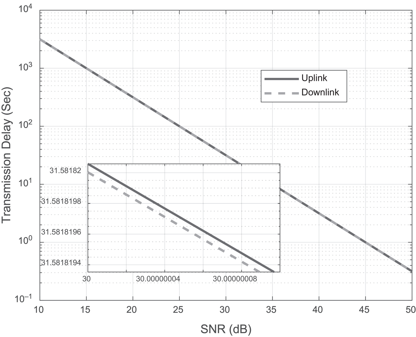
Figure 12.5 Transmission Delay (sec) versus SNR (dB).
Figure 12.6 depicts the relationship between the overall delay and the SNR. This too shows a negative linear relationship; with the increase in SNR, the total delay as well as the processing delay decreases. The total delay is always seen to be greater than the processing delay. At 30 dB SNR, the total delay is 0.16% more than the processing delay.

Figure 12.6 Delay (sec) versus SNR (dB).
From Figure 12.7, the effect on energy consumption due to change in SNR is seen. With increase in SNR, the energy consumption for both the MU and the UAV-BS decreases linearly until it levels off at high SNR (approximately 46dB). We also see that the UAV-BS consumes more energy than MU at all SNRs. When compared at 30dB SNR, it is seen that the UAV-BS consumes 90% more energy than the MU.

Figure 12.7 Energy Consumption (W) versus SNR (dB).
Lastly, Figure 12.8 shows the effect on energy consumption due to increase in the part of task completed (βmq,t). Here it can be seen that initially the energy consumption increases very fast then slows down but continues to increase till the entire task is completed and almost levels off. This is true for both MU and UAV-BS, though the energy consumed by the UAV-BS is greater than the MU at all times. At 40% task completion, the energy consumption of the UAV-BS is 90% greater than that of the MU.
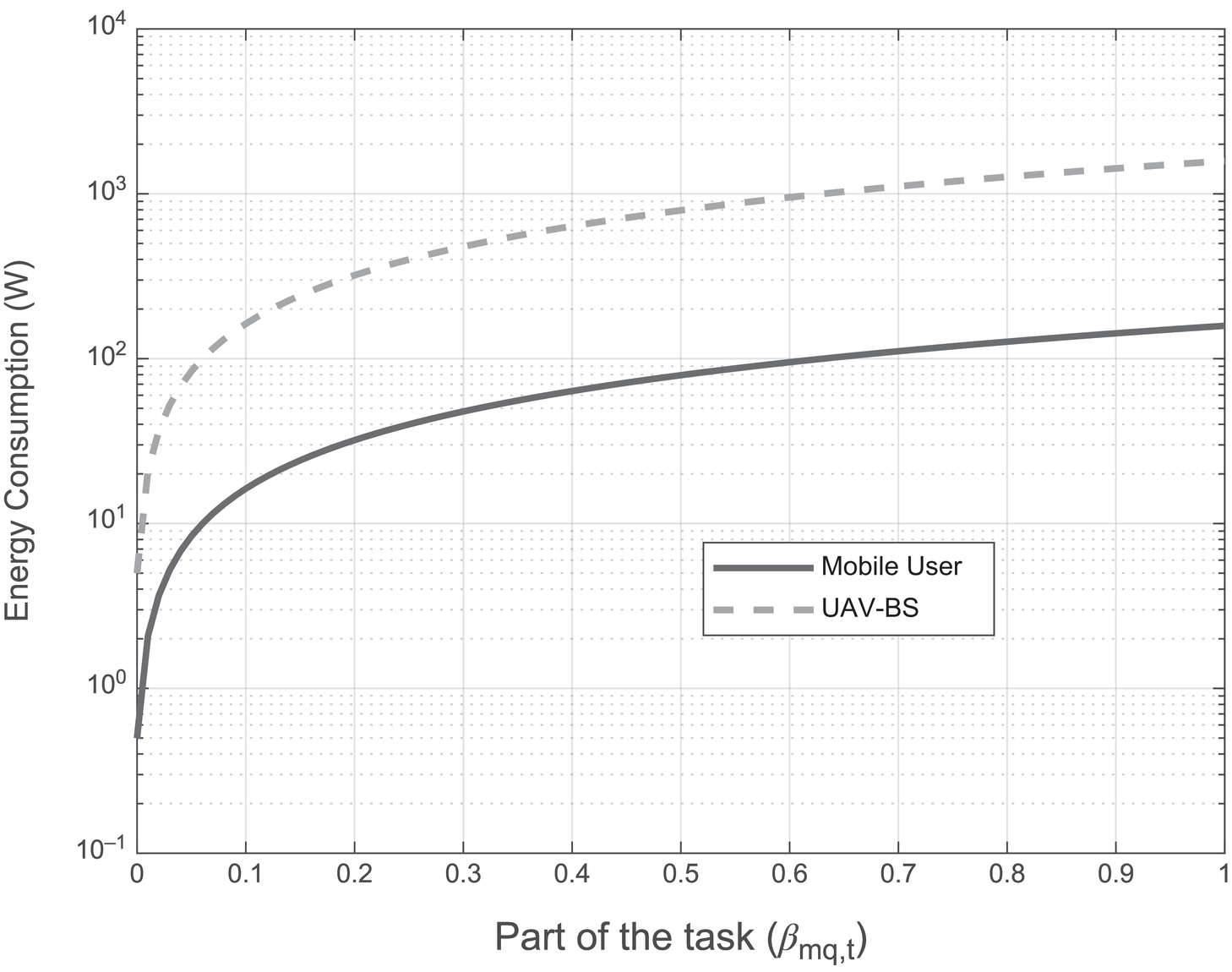
Figure 12.8 Energy Consumption (W) versus Part of the Task (βmq,t).
12.7 Conclusion
Using UAV-BS in wireless network communication to improve its effectiveness is slowly becoming inevitable. Along with the use of UAVs, the use of MEC has been implemented in 5G mobile networks to boost reliability and low latency during communication. Data transfer to and from MUs can be done with great efficiency and accuracy with the implementation of MEC in our network architecture. As discussed in the chapter, there are both some benefits as well as drawbacks of using such a system; however, from numerical results; the benefits outweigh the drawbacks. Our simulation results show that the total delay is 0.16% more than the processing delay at an SNR of 30 dB and the UAV-BS consumes 90% more energy than the MU at 30 dB SNR as well as at 40% task completion. Furthermore, for both uplink and downlink communication, data rate and transmission delay are seen to increase and decrease, respectively, at high SNR when NOMA method is used. This chapter has provided a thorough study on the use of MEC in UAV-BSs and has presented its advantages, disadvantages as well as come up with a proposed system model along with simulation results which can serve as a guideline for further exhaustive research on this topic. In the future we plan to work on energy harvesting [27] and transmit antenna selection [28, 29], that is, find a renewable source of energy to power the UAV-BSs. Further, we want to come up with a better model to decrease energy consumption in the UAVs [30], decrease latency and overcome the issues discussed in the chapter involving the use of MEC in UAV-BSs.
References
- 1. Z. Yang, C. Pan, K. Wang, and M. Shikh-Bahaei, “Energy Efficient Resource Allocation in UAV-Enabled Mobile Edge Computing Networks,” IEEE Transactions on Wireless Communications, vol. 18, no. 9, pp. 4576–4589, Sept. 2019, doi: 10.1109/TWC.2019.2927313.
- 2. O. Bekkouche, T. Taleb, and M. Bagaa, “UAVs Traffic Control Based on Multi-Access Edge Computing,” 2018 IEEE Global Communications Conference (GLOBECOM), Abu Dhabi, United Arab Emirates, 2018, pp. 1–6.
- 3. V. Sharma, I. You, D. N. K. Jayakody. D. G. Reina, and K. R. Choo, “Neural-Blockchain-Based Ultrareliable Caching for Edge-Enabled UAV Networks,” IEEE Transactions on Industrial Informatics, vol. 15, no. 10, pp. 5723–5736, Oct. 2019, doi: 10.1109/TII.2019.2922039.
- 4. F. Zhou, Y. Wu, H. Sun, and Z. Chu, “UAV-Enabled Mobile Edge Computing: Offloading Optimization and Trajectory Design,” 2018 IEEE International Conference on Communications (ICC), Kansas City, MO, 2018, pp. 1–6, doi: 10.1109/ICC.2018.8422277.
- 5. M. Mozaffari, W. Saad, M. Bennis, Y. Nam, and M. Debbah, “A Tutorial on UAVs for Wireless Networks: Applications, Challenges, and Open Problems,” IEEE Communications Surveys & Tutorials, vol. 21, no. 3, pp. 2334–2360, thirdquarter 2019, doi: 10.1109/COMST.2019.2902862.
- 6. L. Gupta, R. Jain, and H. Chan, 2016. “Mobile Edge Computing – An Important Ingredient Of 5G Networks - IEEE Software Defined Networks,”. [online] Available at: https://sdn.ieee.org/newsletter/march-2016/mobile-edge-computing-an-important-ingredient-of-5g-networks [Accessed March 27 2020].
- 7. J. Mundy 2019. “What Is Mobile Edge Computing?,” [online] 5g.co.uk. Available at: https://5g.co.uk/guides/what-is-mobile-edge-computing/ Accessed March 26 2020.
- 8. E. Ahmed, and M. H. Rehmani “Mobile Edge Computing: Opportunities Solutions and Challenges,” Future Generation Computer Systems, vol. 70, pp. 59–63, May 2017.
- 9. Z. Yang, C. Pan, K. Wang, and M. Shikh-Bahaei, “Energy Efficient Resource Allocation in UAV-Enabled Mobile Edge Computing Networks,” IEEE Transactions on Wireless Communications, vol. 18, no. 9, pp. 4576–4589, Sept. 2019, doi: 10.1109/TWC.2019.2927313.
- 10. O. Kalinagac. S. S. Kafiloglu, F. Alagoz, and G. Gur, “Caching and D2D Sharing for Content Delivery in Software-Defined UAV Networks,” 2019 IEEE 90th Vehicular Technology Conference (VTC2019-Fall), Honolulu, HI, USA, 2019, pp. 1–5, doi: 10.1109/VTCFall.2019.8891497.
- 11. N. Zhao et al., “Caching UAV Assisted Secure Transmission in Hyper-Dense Networks Based on Interference Alignment,” IEEE Transactions on Communications, vol. 66, no. 5, pp. 2281–2294, May 2018, doi: 10.1109/TCOMM.2018.2792014.
- 12. N. Abbas, Y. Zhang, A. Taherkordi, and T. Skeie, “Mobile Edge Computing: A Survey,” IEEE Internet of Things Journal, vol. 5, no. 1, pp. 450–451, Feb. 2018.
- 13. Y. Mao, C. You, J. Zhang, K. Huang, and K. B. Letaief, “Mobile Edge Computing: Survey and Research Outlook,” arXiv:1701.01090v3 [cs.IT], Apr. 2017. Accessed 26 March 2020 [Online]. Available at: https://arxiv.org/abs/1701.01090v3.
- 14. G. Wu, Y. Miao, Y. Zang, and A. Barnawi, “Energy Efficient for UAV-Enabled Mobile Edge Computing Networks: Intelligent Task Prediction and Offloading,” Computer Communications, vol. 150, pp. 556–562, 2019.
- 15. H. Sedjelmaci, S. M. Senouci, and N. Ansari, “A Hierarchical Detection and Response System to Enhance Security Against Lethal Cyber-Attacks in UAV Networks,” IEEE Transactions on Systems, Man and Cybernetics: Systems, vol. 48, no. 9, pp. 1594–1606, 2018.
- 16. K. Yoon, D. Park, Y. Yim, K. Kim, S. K. Yang, and M. Robinson, “Security Authentication System Using Encrypted Channel Using UAV Network,” Proceedings of the first IEEE International Conference on Robotic Computing (IRC). IEEE, 2017, pp. 393–398.
- 17. T. Bai, J. Wang, Y. Ren, and L. Hanzo, “Energy-Efficient Computation Offloading for Secure UAV-Edge-Computing Systems,” IEEE Transactions on Vehicular Technology, vol. 68, no. 6, pp. 6074–6087.
- 18. H. Sedjelmaci, A. Boudguiga, I. B. Jemaa, and S. M. Senouci, “An Efficient Cyber Defense Framework for UAV-Edge Computing,” Ad Hoc Networks, vol. 94, 101970, 2019.
- 19. W. Jiang, G. Feng, S. Qin, and Y. Liu, “Multi-Agent Reinforcement Learning Based Cooperative Content Caching for Mobile Edge Networks,” IEEE Access, vol. 7, pp. 61856–61867, 2019.
- 20. N. Abbas, Y. Zhang, A. Taherkordi, and T. Skeie, “Mobile Edge Computing: A Survey,” IEEE Internet of Things Journal, vol. 5, no. 1, pp. 4, Feb. 2018.
- 21. M. Aldababsa, M. Toka, S. Gökçeli, G. K. Kurt, and O. Kucur, “A Tutorial on Nonorthogonal Multiple Access for 5G and Beyond,” Wireless Communications and Mobile Computing, vol. 2018, 2018. doi: 10.1155/2018/9713450
- 22. M. F. Sohail, C. Y. Leow, and S. Won, “Non-Orthogonal Multiple Access for Unmanned Aerial Vehicle Assisted Communication,” IEEE Access, vol. 6, pp. 22716–22727, 2018.
- 23. A. Al-Hourani, S. Kandeepan, and A. Jamalipour, “Modeling Air-To-Ground Path Loss for Low Altitude Platforms in Urban Environments,” Proceedings of IEEE Global Communications Conference (GLOBECOM), Dec. 2014, pp. 2898–2904.
- 24. Q. Feng, L. McGeehan, E. K. Tameh, and A.R. Nix, “Path Loss Models for Air-To-Ground Radio Channels in Urban Environments,” Proceedings of IEEE 63rd Vehicular Technology Conference, vol. 6, May 2006, pp. 2901–2905.
- 25. M. Mozaffari, W. Saad, M. Bennis, and M. Debbah, “Unmanned Aerial Vehicle with Underlaid Device-to-Device Communications: Performance and Tradeoffs,” IEEE Wireless Communications Letters, vol. 3, no. 6, pp. 569–572, Dec. 2014.
- 26. S. Wang, M. Chen, C. Yin, W. Saad, C. S. Hong, S. Cui, and H. V. Poor, “Federated Learning for Task and Resource Allocation in Wireless High Altitude Balloon Networks,” arXiv:2003.09375v1 [eess.SP], 19 Mar. 2020. [Online]. Available at: https://arxiv.org/abs/2003.09375 Accessed March 29 2020.
- 27. S. R. Sabuj and M. Hamamura, “Two-Slope Path-Loss Design of Energy Harvesting in Random Cognitive Radio Networks,” Computer Networks, vol. 142, pp. 128–141, 2018.
- 28. S. R. Sabuj and M. Hamamura, “Energy Efficiency Analysis of Cognitive Radio Network Using Stochastic Geometry,” Proceedings of IEEE CSCN, pp. 245–251, Oct. 2015.
- 29. M. Khan, M. T. Rahman, and S. R. Sabuj, “Transmit Antenna Selection Technique in Random Cognitive Radio Network,” Proceedings of IEEE Region 10 Conference (TENCON), Jeju, Korea, Oct. 2018.
- 30. A. R. Rahul, S. R. Sabuj, M. S. Akbar, H. Jo, and M. A. Hossain, “An Optimization Based Approach to Enhance the Throughput and Energy Efficiency for Cognitive Unmanned Aerial Vehicle Networks,” Wireless Networks, 2020. [Online]. Available: https://doi.org/10.1007/s11276-020-02450-9 Accessed on: September 2020.