
A balanced view, Part I
People often get confused when grappling with the many kinds of balanced, unbalanced, and ground-cancelling inputs and outputs; given the many permutations and variations this is not surprising. Balanced or quasi-balanced connections have been used for many years in professional circles, and are now slowly but apparently steadily increasing in popularity in the more expensive reaches of the hi-fi market. In this area the outputs are usually balanced by driving the cold line with an inverter rather than going for the full quasi-balanced version, and very sensibly so. The input amplifiers are usually the classic one-op-amp differential stage, though now and then some very complicated instrumentation-amp circuits have been used. For some reason no one seems to have picked up on the great merits of ground-cancelling outputs, possibly because of the difficulty of explaining the concept to the paying customers.
These two articles are an attempt to explain the operation of various kinds of inputs and outputs, some obvious, some almost unknown, with guidance on joining them together effectively.
Balanced inputs and outputs have been used for many years in professional audio, but profound misconceptions about their operation and effectiveness still survive. Balanced operation is also making a slow but steady advance into top-end hi-fi, where its unfamiliarity can lead to further misunderstandings. As with most topics in audio technology, the conventional wisdom is often wrong.
A practical balanced interconnect is not always wholly straightforward. Some new variations on input and output stages have emerged relatively recently. For example, a ‘ground-cancelling’ output is not balanced at all, but actually has one output terminal configured as an input. This can come as a surprise to the unwary.
Despite its non-balanced nature, such a ground-cancelling output can render a ground loop innocuous even when driving an unbalanced input. But even an audio professional could be forgiven for being unsure if it still works when it is driving a balanced input. The answer – which in fact is yes – is explained in a second article on this subject, details of which are given later.
Electronic versus transformer balancing
Electronic balancing has many advantages. These include low cost, low size and weight, superior frequency and transient response, and no problems with low-frequency linearity. While it is sometimes regarded as a second-best, it is more than adequate for hi-fi and most professional applications.
Transformer balancing has some advantages of its own – particularly for work in very hostile r.f./e.m.c. environments – but many serious drawbacks. The advantages are that transformers are electrically bullet-proof, retain their common-mode rejection ratio performance forever, and consume no power even at high signal levels. Unfortunately they also generate low frequency distortion, and have high frequency response problems due to leakage reactance and distributed capacitance. Transformers are also heavy and expensive.
The first two objections can be surmounted – given enough extra electronic circuitry – but the last two cannot. Transformer balancing is therefore rare, even in professional audio, and is only dealt with briefly here.
Balancing basics
Balanced connections in an audio system are designed to reject both external noise, from power wiring etc., and also internal crosstalk from adjacent signal cables.
The basic principle of balanced interconnection is to get the signal you want by subtraction, using a three-wire connection. In many cases, one signal wire – the hot or in phase conductor – senses the actual output of the sending unit. The other, the cold or phase-inverted, senses the unit’s output-socket ground, and the difference between them gives the wanted signal.
Any noise voltages that appear identically on both lines, i.e. common-mode signals, are in theory completely cancelled by the subtraction. In real life, the subtraction falls short of perfection, as the gains via the hot and cold inputs will not be precisely the same. The degree of discrimination actually achieved is called the common-mode rejection ratio (cmrr).
The terms hot and cold for in-phase and out-of-phase respectively, are used throughout this article for brevity.
While two wires carry the signal, the third is the ground wire which has the dual duty of both joining the grounds of the interconnected equipment, and electrostatically screening the two signal wires by being in some way wrapped around them. The ‘wrapping around’ can mean:
• A lapped screen, with wires laid parallel to the central signal conductor. The screening coverage is not perfect, and can be badly degraded as it tends to open up on the outside of cable bends.
• A braided screen around the central signal wires. This is more expensive, but opens up less when the wire is bent. Screening is not 100%, but certainly better than lapped screen.
• An overlapping foil screen, with the ground wire – called the drain wire in this context for some reason – running down the inside of the foil and in electrical contact with it. This is usually the most effective as the foil cannot open up on the outside of bends, and should give perfect electrostatic screening. However, the higher resistance of aluminium foil compared with copper braid means that r.f. screening may be worse.
Electrical noise
Noise gets into signal cables in three major ways:
Electrostatic coupling
An interfering signal with significant voltage amplitude couples directly to the inner signal line, through stray capacitance. The situation is shown in Figure 1, with C, C representing the stray capacitance between imperfectly-screened conductors; this will be a fraction of a picofarad in most circumstances. This coupling is unlikely to be a problem in hi-fi systems, but can be serious in studio installations with unrelated signals going down the same ducting.
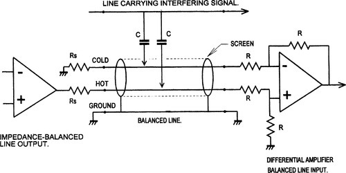
The two main lines of defence against electrostatic coupling are effective screening and low-impedance drive. An overlapping foil screen – such as used on Belden microphone cable – provides complete protection. Driving the line from a low impedance, of the order of 100 Ω or less, means that the interfering signal, having passed through a very small capacitance, is a very small current and cannot develop much voltage across such a low impedance.
For the best results, the impedance must remain low up to as high as frequency as possible; this can be problem as op-amps invariably have a feedback factor that begins to fall from a low, and possibly sub-audio frequency, and this makes the output impedance rise with frequency.
From the point of view of electrostatic screening alone, the screen does not need to be grounded at both ends, or form part of a circuit.1 It must of course be grounded at some point.
Electrostatic coupling falls off with the square of distance. Rearranging the cable-run away from the source of interference is more practical and more effective than trying to rely on very good common-mode rejection.
Magnetic coupling
An e.m.f., Vm, is induced in both signal conductors and the screen, Figure 2. According to some writers, the screen current must be allowed to flow freely, or its magnetic field will not cancel out the field acting on the signal conductors. Therefore the screen should be grounded at both ends, to form a circuit.2

In practice, the field cancellation will be far from perfect. Most reliance is placed on the common-mode rejection of the balanced system, to cancel out the hopefully equal voltages Vm induced in the two signal wires. The need to ground both ends for magnetic rejection is not a restriction, as it will emerge that there are other good reasons why the screens should be grounded at both ends of a cable.
In critical situations, the equality of these voltages is maximised by minimising the loop area between the two signal wires, usually by twisting them tightly together. In practice most audio cables have parallel rather than twisted signal conductors, and this seems adequate most of the time.
Magnetic coupling falls off with the square of distance, so rearranging the cable-run away from the source of magnetic field is usually all that is required. It is unusual for it to present serious difficulties in a domestic environment.
Common-impedance coupling
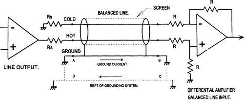
Ground voltages coupled in through the common ground impedance; often called ‘common-impedance coupling’ in the literature.3 This is the root of most ground loop problems. In Figure 3 the equipment safety grounds cause a loop ABCD; the mere existence of a loop in itself does no harm, but it is invariably immersed in a 50 Hz magnetic field that will induce mains-frequency current plus odd harmonics into it. This current produces a voltage drop down the non-negligible ground-wire resistance, and this once again effectively appears as a voltage source in each of the two signal lines. Since the cmrr is finite a proportion of this voltage will appear to be differential signal, and will be reproduced as such.
A common source of ground-loop current is the connection of a system to two different ‘grounds’ that are not actually at the same a.c. potential. The classic example of this is the addition of a ‘technical ground’ such as a buried copper rod to a grounding system which is already connected to ‘mains ground’ at the power distribution board. In most countries this ‘mains ground’ is actually the neutral conductor, which is only grounded at the remote transformer substation. The voltage-drop down the neutral therefore appears between ‘technical ground’ and ‘mains ground’ causing large currents to flow through ground wires.
A similar situation can occur when water-pipes are connected to ‘mains ground’ except that interference is not usually by a common ground impedance; however the unwanted currents flowing in the pipework generate magnetic fields that may either create ground loops by induction, or interfere directly with equipment such as mixing consoles.
In practice, ground voltages cause a far greater number of noise problems than the other mechanisms, in both hi-fi and professional situations.
Even there is no common-impedance coupling, ground currents may still enter the signal circuit by transformer action. An example of such a situation is where the balanced line is fully floating and not galvanically connected to ground – which is only possible with a transformer-to-transformer connection.
The shield wire or foil acts as a transformer primary while the signal lines act as secondaries; if the magnetic field from the shield wire is not exactly uniform, then a differential noise voltage appears across the signal pair and is amplified as if it were a genuine signal. This effect is often called shield-current-induced-noise, or SCIN, and cables vary in their susceptibility to it according to the details of their construction.4
Fortunately the level of this effect is below the noise-floor in most circumstances and with most cables, for once a differential-mode signal has been induced in the signal lines, there is no way to discriminate against it.
From this summary I deduce there are two principle effects to guard against; electrostatic coupling, and the intrusion of unwanted voltages from either magnetic coupling or ground-loop currents.
Electrostatic interference can be represented by notional current sources connected to both signal lines; these will only be effectively cancelled if the line impedances to ground are the same, as well as the basic cmrr being high. The likely levels of electrostatic interference current in practice are difficult to guess, so the figures I give in the second article are calculated from applying 1 mA to each line; this would be very severe crosstalk, but it does allow convenient relative judgements to be made.
Magnetic and ground-voltage interference can be represented by notional voltage-sources inserted in both signal lines and the ground wire; these are not line-impedance sensitive and their rejection depends only on the basic cmrr, as measured with low-impedance drive to each input. Similarly ground-voltage interference can be represented by a voltage-source in the ground wire only.
Both input and output are voltages so the cmrr can be quoted simply as a ratio in decibels, without specifying any level.
Line outputs
A line output is expected to be able to drive significant loads, partly because of a purely historical requirement to drive 600 Ω, and partly to allow the parallel feed of several destinations. Another requirement is a low source impedance − 100 Ω or less – to make the signal robust against capacitive crosstalk, etc.
There are many line output and input arrangements possible, and the results of the various permutations of connection are not always entirely obvious. An examination of the output types in use yields List 1.
Unbalanced output
There are only two physical output terminals – signal and ground, Figure 4(a). A third terminal is implied in Figure 4(a), emphasising that it is always possible to connect the cold wire in the cable to the ground at the transmitting (output) end.
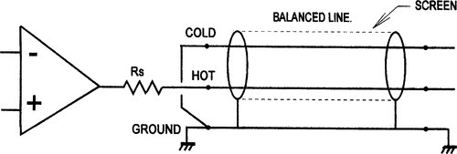
The output amplifier is almost always buffered from the line shunt-capacitance by a resistor Rs in the range 33 to 100 Ω, to ensure stability. This unbalances the line impedances. If the output resistance is taken as 100 Ω worst-case, and the cold line is simply grounded as in Figure 4(a), then the presence of Rs degrades the common-mode rejection ratio to − 46 dB, even if the balanced input at the other end of the cable has perfectly matched resistors.
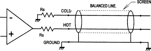
Impedance balanced output
There are now three physical terminals, hot, cold, and ground, Figure 4(b). The cold terminal is neither an input nor an output, but a resistive termination with the same resistance Rs as the hot terminal output impedance. This type of output is intended for use with receiving equipment having balanced inputs. The presence of the second Rs terminated to output ground makes the impedance on each signal line almost exactly the same – apart from op-amp output impedance limitations – so that good rejection is achieved for both common-mode ground voltages and electrostatic interference.
If an unbalanced input is being driven, the cold terminal on the transmitting (output) equipment can be either shorted to ground locally or left open-circuit without serious consequences. Either way all the benefits of balancing are lost.
The use of the word ‘balanced’ is unfortunate as this implies anti-phase outputs, which are not present.
Ground-cancelling output
Also called a ground-compensated output, this arrangement is shown in Figure 5(a).
This allows ground voltages to be cancelled out even if the receiving equipment has an unbalanced input. It prevents any possibility of creating a phase error by miswiring. It separates the wanted signal from the unwanted by addition at the output end of the link, rather than by subtraction at the input end.
If the receiving equipment ground differs in voltage from the sending ground, then this difference is added to the output so that the signal reaching the receiving equipment has the same voltage superimposed upon it. Input and ground therefore move together and there is no net input signal, subject to the usual resistor tolerances.
The cold pin of the output socket is now an input, and must have a unitygain path summing into the main signal-output going to the hot output pin. It usually has a very low input impedance equal to the hot terminal output impedance.
It is unfamiliar to most people to have the cold pin of an output socket as a low impedance input, and this can cause problems. Shorting it locally to ground merely converts the output to a standard unbalanced type. If the cold input is left unconnected then there should be only a very small noise degradation due to the very low input impedance of Rs.
Ground-cancelling outputs would appear to be very suitable for hi-fi use, as they are an economical way of making ground-loops innocuous. However, I am not aware that they have ever been used in this field.
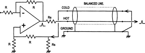
Balanced output
The cold terminal is now an active output, producing the same signal as the hot terminal but phase-inverted, Figure 5(b). This can be simply done by using an op-amp stage with a gain of minus one to invert the normal inphase output. Phase spikes are shown on the diagram to emphasise these phase relationships.

The in-phase signal itself is not degraded by passing through an extra stage and this can be important in quality-critical designs. The inverting output must not be grounded; if not required it can simply be ignored.
Unlike quasi-floating outputs, it is not necessary to ground the cold pin to get the correct gain for unbalanced operation, and it must not be grounded by mistake, because the inverting op-amp will then spend most of its time in current-limiting, probably injecting unpleasant distortion into the preamp grounding system, and possibly suffering unreliability. Both hot and cold outputs must have the same output impedance Rs to keep the line impedances balanced.
A balanced output has the advantage that it is unlikely to crosstalk to other lines, even if they are unbalanced. This is because the current injected via the stray capacitance from each crosstalking line cancels at the receiving end.
Another advantage is that the total signal level on the line is increased by 6 dB, which can be valuable in difficult noise situations. All balanced outputs give the facility of correcting phase errors by deliberately swopping hot and cold outputs. This tactic is however a double-edged sword, because it is probably how the phase became wrong in the first place.
This form of balanced output is the norm in hi-fi balanced interconnection, but is less common in professional audio, where the quasifloating output gives more flexibility.
Quasi-floating output
This kind of output, Figure 6, approximately simulates a floating transformer winding; if both hot and cold outputs are driving signal lines, then the outputs are balanced, as if a centre-tapped output transformer were being used.
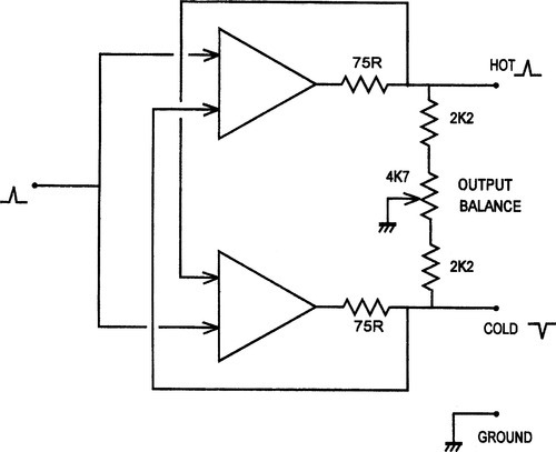
If, however, the cold output is grounded, the hot output doubles in amplitude so the total level is unchanged. This condition is detected by the current-sensing feedback taken from the outside of the 75 Ω output resistors. Current driven into the shorted cold output is automatically reduced to a low level that will not cause problems.
Similarly, if the hot output is grounded, the cold output doubles in amplitude and remains out of phase; the total hot-cold signal level is once more unchanged. This system has the advantage that it can give the same level into either a balanced or unbalanced input without rewiring connectors. 6 dB of headroom is however lost.
When an unbalanced input is being driven, the quasi-floating output can be wired to work as a ground-cancelling connection, with rejection of ground noise no less effective than the true balanced mode. This requires the cold output to be grounded at the remote (input) end of the cable. Under adverse conditions this might cause h.f. instability, but in general the approach is sound. If you are using exceptionally long cable, then it is wise to check that all is well.
If the cold output is grounded locally, i.e. at the sending end of the cable, then it works as a simple unbalanced output, with no noise rejection. When a quasi-floating output is used unbalanced, the cold leg must be grounded, or common-mode noise will degrade the noise floor by at least 10 dB, and there may be other problems. In both of the unbalanced cases the maximum signal possible on the line is reduced by 6 dB.
Quasi-floating outputs use a rather subtle circuit with an intimate mixture of positive and negative feedback of current and voltage. This performs the required function admirably; its only drawback is a tendency to accentuate circuit tolerances, and so a preset resistor is normally required to set the outputs for equal amplitude; the usual arrangement is shown in Figure 6.
If the balance preset is not correctly adjusted one side of the output will clip before the other and reduce the total output headroom. After factory setting this preset should not need to be touched unless the resistors in the circuit are replaced; changing the op-amp should make no difference.
The balancing network consists of a loading resistor to ground on each output; in this respect the output characteristics diverge from a true floating output, which would be completely isolated from ground. These loading resistors are lower than the input impedance of typical balanced inputs. So if simple differential amplifiers are used with unequal input impedances, (see the section on line inputs, below) the output balance is not significantly disturbed and clipping remains symmetrical on the hot and cold outputs.
Quasi-floating outputs are often simply referred to as ‘balanced’ or ‘electronically-balanced’, but this risks serious confusion as the true balanced output described earlier must be handled in a completely different way from quasi-floating.
True floating transformer output
This can be implemented with a transformer if galvanic isolation from ground is required. The technique is rarely used.
The second article in this pair looks at line inputs in detail, examines what happens when the different kinds of input and output are connected together, and deals with the philosophy of audio system wiring.