
Inside mixers
When this was written, mixing console design was my day job, so to speak, and I was doing hi-fi design purely as a spare-time pursuit. Having been responsible for many of the contemporary improvements in mixing console design (such as the padless mic amp and the active panpot) I thought it might be a good plan to publicise these in Electronics World. After consulting those set in authority over me, a fine balance was struck between offering solid, accurate technical content and not giving away too much to our competitors. The padless microphone amp and the active panpot could be described in some detail, as they were fully covered by patents.
I was a bit more cautious about the electronic switching, as that was not patented. The whole subject of electronic switching was eventually revealed in two articles in 2004 and they are also collected in this book.
Recording technology has changed greatly since this article was written, and the frequent references to tape-machines seem very dated. Yet, that was how it was then.
A large mixing console arguably represents the most demanding area of audio design. The steady advance of digital media demands that every part of the chain that takes music from performer to consumer must be near-perfect, as the comfortable certainty that everything will be squeezed through the quality bottleneck of either analogue tape or vinyl disc now looks very oldfashioned. This chapter was prompted by the introduction of the Soundcraft 3200 recording console, which is believed to have the highest performance in terms of noise, crosstalk and linearity of any console ever built.
Competition to sell studio time becomes more cut-throat with every passing week, and it is clear that advances in console quality must not harm cost- effectiveness. The only way to reconcile these demands is to innovate and to keep a very clear view as to what is really necessary to meet a demanding specification; in other words the way forward is to use conventional parts in an unconventional way, rather than simply reaching for the most expensive op-amp in the catalogue.
The technical problems that must be over-come in a professional mixing console are many. A large number of signals flow in a small space and they must be kept strictly apart until the operator chooses to mix them; crosstalk must be exceedingly low.
There may be up to 64 input channels, each with many stages, and all having the potential to add distortion and noise to the precious signal. Even summing these signals together, while sounding trivially easy, is in practice a major challenge. In short, requirements are much more demanding than those for the most expensive hi-fi equipment, because degradation introduced at the recording stage can never be retrieved.
Major functions of consoles are largely standardised, although there is much scope for detailed variation. Figure 1 shows a typical system diagram for a split (separate groups) mixing console. The technique of multi-track recording is explained in the appendix at the end of this article.

Figure 2 shows a typical input channel for a mixing console. The input stage provides switchable balanced mic and line inputs; the mic input has an impedance of 1–2 kΩ, which provides appropriate loading for a 200 Ω mic capsule, while the line input has a bridging impedance of not less than 10 kΩ. This stage gives a wide range of gain control and is followed immediately by a high-pass filter (usually − 3 dB at 100 Hz) to remove low-frequency disturbances.
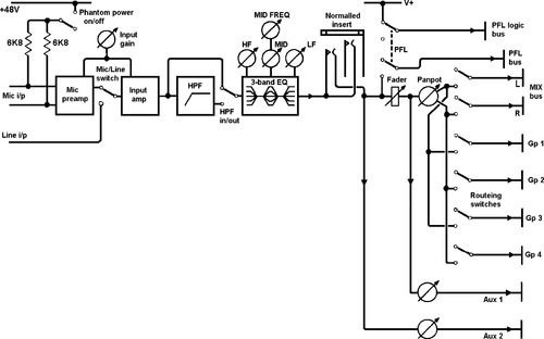
The tone-control section (universally known in the audio business as ‘EQ’ or equalisation) typically includes one or more mid-band resonance controls as well as the usual shelving Baxandall-type high and low controls. Channel level is controlled by a linear fader and the panpot sets the stereo positioning, odd group numbers being treated as left, and even as right. The prefade-listen (PFL) switch routes the signal to the master module independently of all other controls; a logic bus signals the master module to switch the studio monitoring speakers from the normal stereo mix bus to the PFL bus, allowing any specific channel to be examined in isolation.
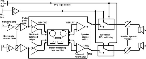
Figure 3 shows a typical group module and Figure 4 the basics of a master section; a manual source-select switch allows quality checking of the final stereo recording and two solid-state switches replace the stereo monitor signal with the PFL signal whenever a PFL switch anywhere on the console is pressed.

Microphone inputs
The microphone preamplifier is a serious design challenge. It must provide from 0 to 70 dB of gain to amplify deafening drum-kits or discreet dulcimers, present an accurately balanced input to cancel noise pickup in long cables and generate minimal internal noise. It must also be able to withstand + 48 V DC suddenly applied to the inputs (for phantom-powering internal preamps in capacitor mics) while handling microvolt signals. The Soundcraft approach is to use standard parts, which are proven and costeffective through quantity production, in new configurations. The latest mic preamplifier design, as used on the Series 3200, is new enough to be covered by patent protection.
It is now rare to use input transformers to match the low-impedance (150–200 Ω) microphone to the preamplifier, since the cost and weight penalty is serious, especially when linearity at low frequencies and high levels is important. The low-noise requirement rules out the direct use of op-amps, since their design involves compromises that make them at least 10 dB noisier than discrete transistors at low impedance.
This circuit, shown in Figure 5, therefore uses a balanced pair of lownoise, low-Rb PNP transistors as an input stage, working with two op-amps to provide load-driving capability and raw open-loop gain to linearise signal handling. Preamplifier gain is spread over two stages to give a smooth 0–70 dB gain range with the rotation of a single knob. This eliminates the switched 20 dB attenuator that is normally required to give the lower gain values, not only saving cost and complication, but also avoiding the noise deterioration and CMRR degradation that switched attenuators impose. The result is an effective input stage that is not only quieter, but also more economical than one using specialised low-noise op-amps.

Equalisation
Since large recording consoles need sophisticated and complex tone-control systems, unavoidably using large numbers of op-amps, there is a danger that the number of active elements required may degrade the noise performance.
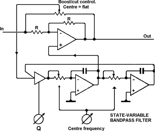
A typical mid-band EQ that superimposes a + 15 dB resonance on the flat unity-gain characteristic is shown in Figure 6. A signal is tapped from the forward path, put through a state-variable band-pass filter which allows control of centre-frequency and Q, and then added back. To improve noise performance, the signal level at all locations (in all conditions of frequency, Q, and boost/cut) was assessed, and it proved possible to double the signal level in the filter over the usual arrangement, while maintaining full headroom. The signal returned into the forward path is then attenuated to maintain the same boost/cut, and the noise added is thus reduced by about 6 dB.
Auxiliary sends: foldback and effects
The auxiliary sends of a console represent an extra mixing system that works independently of the main groups; the number and configuration of these sends have a large effect in determining the overall versatility of the console. Each send control provides a feed to a console-wide bus; this is centrally summed and then sent out of the console.
Sends come essentially in two kinds: prefade sends, which are taken from before the main channel fader, and post-fade sends, which take their feed from after the fader, so that the final level depends on the settings of both. There may be anything from one to twelve sends available, often switchable between pre and post. Traditionally, this means laboriously pressing a switch on every input module, since it is most unlikely that a mixture of pre and post sends on the same bus would be useful; the Series 3200 minimises the effort by setting pre/post selection for each bus from a master switch that controls solid-state pre/post switching in each module.
Prefade sends are normally used for ‘foldback’; i.e. sending the artist a headphone feed of what he/she is perpetrating, which is important if electronic manipulation is part of the creative process, and essential if the artist is adding extra material that must be in time with that already recorded. In the latter case, the existing tracks are played back to the artist via the prefade sends on the monitor sections.
Postfade sends are used as effects sends; their source is after the fader, so that the effect will be faded down at the same rate as the untreated signal, maintaining the same ratio. The sum of all feeds to a given bus is sent to an external effects unit and the output of this returned to the console. This allows many channels to share one expensive device (this is particularly applicable to digital reverb) and is often more appropriate than the alternative of patching a processor into the channel insert point.
‘Effect returns’ may be either modules in their own right or a small subdivision of the master section. The returned effect, which may well now be in stereo, the output of a digital reverb, for example, is usually added to the stereo mix bus via level and pan controls. EQ is also sometimes provided.
Panpot
To give smooth stereo panning without unwanted level changes, the panpot should theoretically have a sine/cosine characteristic; such components exist, but they are prohibitively expensive and so most mixing consoles use a dual linear pot. with its law bent by a pull-up resistor, as shown in Figure 7(a).

This not only gives a mediocre approximation of the required law, but also limits the panning range, since the pull-up signal passes through the wiper contact resistance (usually greater than the end-of-track resistance) and limits the attenuation the panpot can provide when set hard left or right. This limitation is removed in the Soundcraft active panpot shown in Figure 7b by replacing the pull-up with a negative-impedance-converter that modulates the law-bending effect in accordance with the panpot setting, making a close approach to the sine law possible. There is no pull-up at the lower end of the wiper travel, when it is not required, so the left-right isolation using a good-quality pot is improved from approx − 65 to − 90 dB. This has also been made the subject of patent protection.
Summing
One of the main technical challenges in console design is the actual mixing of signals. This is done almost (but not quite) universally by virtual-earth techniques, as in Figure 8(a). A summing amplifier with shunt feedback is used to hold a long mixing bus at apparent ground, generating a sort of audio black hole; signals fed into this via mixing resistors apparently vanish, only to reappear at the output of the summing amplifier, as they have been summed in the form of current. The elegance of virtual-earth mixing, as opposed to the voltage-mode summing technique in Figure 8(b), is that signals cannot be fed back out of the bus to unwanted places, as it is effectively grounded, and this can save massive numbers of buffer amplifiers in the inputs.

There is, however, danger in assuming that a virtual earth is perfect; a typical opamp summer loses open-loop gain as frequency increases, making the inverting input null less effective. The ‘bus residual’ (i.e. the voltage measurable on the summing bus) therefore increases with frequency and can cause inter-bus crosstalk in the classic situation with adjacent buses running down an IDC cable.
Increasing the number of modules feeding the mix bus increases the noise gain; in other words the factor by which the noise of the summing amplifier is multiplied. In a large console, which might have 64 inputs, this can become distinctly problematic. The Soundcraft solution is to again exploit the low noise of discrete transistors coupled to fast opamps, in configurations similar to the mic preamps.
These sum amplifiers have a balanced architecture that inherently rejects supply-rail disturbances, which can otherwise affect LF crosstalk performance.
As a console grows larger, the mix bus system becomes more extensive, and therefore more liable to pick up internal capacitive crosstalk or external AC fields. The 3200 avoids internal crosstalk by the use of a proprietary routeing matrix construction which keeps the unwanted signal on a bus down to a barely measurable 120 dB. This is largely a matter of keeping signal voltages away from the sensitive virtual-earth buses. Further improvement is provided by the use of a relatively low value of summing resistor; this also keeps the noise down, although since it drops as the square-root of the resistor value, at best, there is a clear limit to how far this approach will work before drive power becomes excessive; 4.7kΩ is a reasonable minimum value.
External magnetic fields, which are poorly screened by the average piece of sheet steel, are rejected by the balanced nature of the Series 3200 mix buses, shown in Figure 8c. The operation is much the same as a balanced input; each group has two buses, which run physically as close together as possible and the group reads the difference between the two, effectively rejecting unwanted pickup. The two buses are fed in antiphase from each input, effectively doubling the signal level possible for a given supply voltage. Overall mixing noise is reduced by 3 dB, the signal level is 6 dB up and the noise, being uncorrelated for each bus, only increases by 3 dB.
The obvious method of implementing this is to use two summing amplifiers and then subtract the result. In the 3200, this approach is simplified by using one symmetrical summing amplifier to accept the two antiphase mix buses simultaneously; this reduces the noise level as well as minimising parts cost and power consumption. The configuration is very similar to that of the balanced mic amp, and therefore gives low noise as well as excellent symmetry.
Solid-state switching
There are two main applications for electronic switching in console design. The first is ‘hard’ switching to reconfigure signal paths, essentially replacing relays with either JFETs (Figure 9(a)) or 4016-type analogue gates which, since they are limited to 18 V rails and cannot handle the full voltage swing of an opamp audio path, must be used in current mode, as shown in Figure 9(b). Note that when gate 1 is off, gate 2 must be on to ensure that a large voltage does not appear on gate 1 input. Full voltage range gates do exist but are very expensive.

Secondly, there is channel muting; this not a hard switch, since an unacceptable click would be generated unless the signal happened to be at a zero-crossing at the instant of switching; the odds are against you. The Series 3200 therefore implements muting as a fast-fade that takes about 10 ms; this softens transients into silence while preserving time-precision. It is implemented by a series-shunt JFET circuit, with carefully synchronised ramp voltages applied to the FET gates.
Performance factors
Primary requirements of modern consoles are very low noise and minimal distortion. Since a comprehensive console must pass the audio through a large number of circuit stages (perhaps over 100 from microphone to final mixdown) great attention to detail is essential at each stage to prevent a buildup of noise and distortion; the most important tradeoff is the impedance of the circuitry surrounding the opamp, for if this too high Johnson noise will be increased, while if it is too low an opamp will exhibit nonlinearity in struggling to drive it.
The choice of device is also critical, for cost considerations discourage the global use of expensive chips. In a comprehensive console like the 3200 with many stages of signal processing, this becomes a major concern; nonetheless, after suitable optimisation, the right-through THD remains below 0.004% at 20 dB above the normal operating level. At normal level it is unmeasurable.
Appendix the technique of multitrack recording
Multitrack recording greatly enhances the flexibility of recording music. The availability of a number of tape tracks (anywhere between 4 and 32 on one reel of tape) that can be recorded and played back separately allows each instrument a dedicated track, the beauty of this being that one mistake does not ruin the whole recording; only a single part need be done again. The multitrack process is in two basic halves; recording individual tracks (or ‘tracklaying’) and mixdown to stereo.
Recording
Normally only one or two parts are recorded at once, though it quite possible to dedicate five or six tracks to a drum kit. The initial sound, whether captured by a microphone or fed in directly from a synthesiser line output, is usually processed as little as possible before committing it to tape; subsonic filtering and perhaps compression or limiting are used, but most effects are carefully avoided because they are usually impossible to undo later. You can easily add reverberation, for example, but just try removing it.
Recording is performed via the input modules, this being the only place where microphone preamps are fitted. The inputs are mixed together into groups if required; performers doing backing vocals might use four or five microphones, but these would almost certainly be mixed down to a stereo pair of groups at the recording stage, so that only two tape tracks are taken up. A bank of switches on each input module determines which group shall be fed; this is known as the routing matrix. Combined group outputs are then sent to tape; however a ‘group’ is usually used even if only one signal is being recorded, as this is the part of the console permanently connected to the multitrack.
It is clearly essential that new parts are performed in time with the material already on tape and also that the recording engineer can make up a rough impression of the final mix as recording proceeds. Thus continually replaying already-recorded material is almost as important as recording it in the first place. During recording, the tape tracks already laid down are replayed through ‘monitor sections’ which are usually much-simplified inputs giving limited control; this keeps the more flexible inputs free for material that is actually being recorded. One of the major features of the Series 3200 is that the monitor sections are unusually capable, having facilities almost identical to the inputs and allowing much more accurate assessment of how the mix is progressing, reducing learning time for operators.
Mixdown
When the tracklaying process is complete, there are 16 or more separate tape tracks that must be mixed down to stereo. Major manipulations of sound are done at this mixdown stage; since the multitrack tape remains unaltered, the resulting stereo being recorded on a separate two-track machine, any number of experiments can be performed without doing anything irrevocable.
Multitrack replay signals now enter the console through the input channels, so that the maximum number of facilities are available. Linear channel faders set the relative levels of the musical parts, while the rotary panpots (panoramic potentiometers) define the placement of instruments in the stereo sound field by setting the proportion of signal going to left and right mix buses. The monitor sections are now redundant, and can therefore be used either as extra inputs to the stereo mix, perhaps for keyboards, or to return effects.
Virtual mixing
The advent of computer-based sequencers has given rise to the term ‘virtual mixing’. Keyboard/synthesiser parts of the musical masterwork are not committed to multitrack, but instead stored in the form of MIDI sequencer data. This can be replayed at any time, providing means of synchronising it to the acoustic parts on the multitrack exist; this requires one tape track to be dedicated to some form of timecode.
The advantages are, firstly, that this gives almost any number of extra ‘virtual tracks’, and secondly, that the synthesiser parts suffer minimal degradation as they avoid one generation of tape storage.