
Loudspeaker undercurrents
I must admit that when I first read that exotic waveforms that increased the current demands of speakers by several times could be thought up, I was a bit sceptical. Well, actually, I was very sceptical. However, I was wrong to be so untrusting. Simulating a very simple analog of a loudspeaker showed that transient currents of considerable size can be made to flow if careful adjustments are made to the stimulus waveform.
However, the implications of this for practical amplifier design are much less clear. The square-edged waveforms required to induce current-enhancement do not resemble speech or music at all, and in the intervening years since the article was published it has gradually become clearer that they do not exist in real life speech and music. It therefore seems that the extent to which such alarming current-enhancement occurs is negligible, and it need not be considered in the design process. Timely support for this view comes from an article called ‘Current Affairs’ by Keith Howard, in Hi-Fi News (Feb 2006) which finds no evidence of current-enhancement at all.
It is easy to show that the voltage/current phase shifts in reactive loudspeaker loads increase the peak power dissipation in a cycle, using sine wave test signals of varying frequency.1 The effect of this on device selection in output stages is complicated by the inability to treat power ratings as average power, for as far as safe-operating areas are concerned, low audio frequencies count as d.c.
But sinewave studies do not give insight into what can happen with arbitrary waveforms. When discussing amplifier current capability and loudspeaker loading, it is often said that it is possible to synthesise special waveforms that provoke a loudspeaker into drawing a greater current than would at first appear to be possible. This is usually stated without further explanation. Since I too have become guilty of this, 1 it seemed time to make a quick investigation into just how such waveforms are constructed.
The possibility of unexpectedly big currents was raised by Otala, 2 and expanded on later.3 But these information sources are not available to everybody. The effect was briefly demonstrated in EW by Cordell,4 but this was a long time ago.
Speaker model
Figure 1 is the familiar electrical analogue of a single speaker unit. Component Rc is the resistance and Lc the inductance of the voice coil. In series, Lr and Cr represent the resonance of cone mass and suspension compliance, while Rr controls the damping. These three components model the impedance characteristics of the real electromechanical resonance.

Voice-coil inductance is 0.29 mH, and coil resistance 6.8 Ω. These figures are typical for a 10 in bass unit of 8 Ω nominal impedance. Measurements on this load will never show an impedance below 6.8 Ω at any frequency. This makes it easy to assume that the current demands can never exceed those of a 6.8 Ω resistance. This is not true.
To get unexpectedly high currents moving, the secret is to make use of the energy storage in the circuit reactances, by applying an asymmetrical waveform with transitions carefully matched to the speaker resonance.
Simulating the effects
Figure 2 shows PSpice simulation of the currents drawn by the circuit of Figure 1. The rectangular waveform is the current in a reference 8 Ω resistance driven with the same waveform. A ± 10 V output limit is used here for simplicity but this will in practice be higher, a little below the rail voltages.
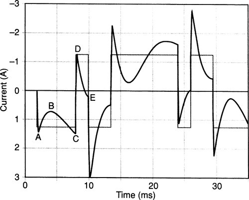
At the start of the waveform at A, current flows freely into Cr but then reduces to B as the capacitance charges. Current is slowly building up in Lr, so the total current drawn increases again to C. A positive transition to the opposite output voltage then takes us to point D, which is not the same as A because energy has been stored in Lr during the long negative period.
A carefully-timed transition is made at E, at the lowest point in this part of the curve. The current change is the same amplitude as at D, but since it starts off from a point where the current is already negative, the final peak goes much lower to 2.96 A, 2.4 times that for the 8 Ω case. I call this the current timing factor (CTF).
And with multiple speakers?
Otala has shown that the use of multi-way loudspeakers, and more complex electrical models, allows many more degrees of freedom in maximising the peak current, and gives a worst case current timing factor of 6.6 times.3
Taking an amplifier designed to give 50 W into 8 Ω, the peak current into an 8 Ω resistance is 3.53 A; amplifiers are usually designed to drive 4 Ω or lower to allow for impedance dips and this doubles the peak current to 7.1 A. In Ref. 3, Otala implies that the peak capability should be at least 23 A, but this need only be delivered for less than a millisecond.
The vital features of the provocative waveform are the fast transitions and their asymmetrical timing, the latter varying with speaker parameters. The waveform in Figure 2 uses ramped transitions lasting 10 μs; as the transitions are made slower the peak currents are reduced. Nothing much changes up to 100 μs, but with 500 μs transitions the current timing factor is reduced from 2.4 to 2.1.
Without doing an exhaustive survey, it is impossible to know how many power amplifiers can supply six times the nominal peak current required. I suspect there are not many. Is this therefore a neglected cause of real audible impairment? I think not, because:
• Music signals do not contain high-level rectangular waveforms, nor trapezoidal approximations to them. A useful step would be to statistically evaluate how often – if ever – waveforms giving significant peak current enhancement occur. As an informal test, I spent some time staring at a digital scope connected to general-purpose rock music, and saw nothing resembling the test waveform of Figure 2. Whether the asymmetrical timings were present is not easy to say; however the large-amplitude vertical edges were definitely not.
• If an amplifier does not have a huge current-peak capability, then the overload protection circuitry will hopefully operate. If this is of a non-latching type that works cleanly, the only result will be rare and very brief periods of clipping distortion when the loudspeaker encounters a particularly unlucky waveform. Such transient distortion is known to be inaudible and this may explain why the current enhancement effect has attracted relatively little attention to date.