
Class distinction
Some ideas lie fallow for a long time before they see the public light of day, especially if I am involved. This one had been at the back of my mind for some 10 years; the simple thought that complex output stages could be analysed into combinations of a few elementary classes, much as atoms are made of elementary particles.
The goal was not mere classification, but setting up a formal system whereby possible new combinations of operating principles would become evident, and some of these are dealt with – rather briefly, I’m afraid, but space was running out – at the end of the article.
The article was apparently well received at the time, and I received some nice letters, but whether it will have any real impact on the naming of amplifiers remains to be seen. I have to say that my own prediction is no, it will not.
Power amplifiers are usually distinguished by their operating class – A, AB or B, and so on. Unfortunately this classification scheme only begins to address the problem, as amplifiers come in many more than three kinds. There is current-dumping, Class-G, error-correction, and so on. Amplifiers that work in quite different ways are all called ‘B’ or ‘AB’, and there is still confusion between B and AB in many quarters.
Traditionally, further letters such as G, H, and S have been used to describe more complex configurations. It occurred to me that rather than proliferating amplifier classes on through the alphabet, it might be better to classify amplifiers as combinations of the most basic classes of device operation.
It may be optimistic to think that this proposal will be adopted overnight, or indeed ever. Nevertheless, it should at least stimulate thought on the many different kinds of power amplifier and the relationships between them.
Class structure
At the most elementary level, there are five classes of device operation, as outlined in the panel. More sophisticated amplifier types such as Class-G, Glass-S, etc., are combinations of these basic classes. Class-E remains an rf-only technology,7 while Class-F does not apparently exist.
All the operating classes above work synchronously with the signal. The rare exceptions are amplifiers that have part of their operation driven by the signal envelope rather than the signal itself.
Krell8 has produced Class-A amplifiers with a quiescent current that is rapidly increased by a sort of noise-gate side-chain, but slowly decays. An interesting study of a syllabic Class-G amplifier with envelope-controlled rail switching was presented in Ref. 9.
Combinations of classes
The basic classes mentioned in the panel on the right have been combined in many ways to produce the amplifier innovations that have appeared since 1970. Since the standard output stage could hardly be simplified, all of these involve extra power devices that modify how the voltage or current is distributed.
Assuming the output stage is symmetrical about the central output rail, then above and below it there will be at least two output devices connected together, in either a series or parallel format. Since these two devices may operate in different classes, two letters are required for a description, with punctuation – a dot or plus sign – between them to indicate parallel or series connection.
Parallel or series connection
In parallel, i.e., shunt, connection, output currents are summed, the intention being either to increase power capability, which does not affect basic operation, or to improve linearity.
A subordinate aim is often the elimination of the Class-B bias adjustment. The basic idea is usually a small high-quality amplifier correcting the output of a larger and less linear amplifier. For a parallel connection the two class letters are separated by a dot, i.e. ‘•’.
In a series connection the voltage drop between supply rail and output is split up between two or more devices, or voltages are otherwise summed to produce the output signal. Since the collectors or drains of active devices are not very sensitive to voltage, such configurations are usually aimed at reducing overall power dissipation rather than enhancing linearity. Series connection is denoted by a plus sign between the two Class letters.
The order of the letters is significant. The first letter denotes the class of that section of the amplifier that actually controls the output voltage. Such a section must exist – if only because the global negative feedback must be taken from one specific point – and the voltage at this point is the controlled quantity. The shunt configurations are dealt with first; see Table 1.
Table 1
Sub-class definitions
| Parallel | ||
| A • B | Sandman Class-S scheme | Figure 1 |
| A • C | Quad current-dumping | |
| B • B | Self Load-Invariant amplifier | |
| B • C | Crown and Edwin types | Figure 2 |
| B • C | Class-G shunt. (Commutating) 2 rail voltages | Figure 3 |
| B • C • C | Class-G shunt. (Commutating) 3 rail voltages | Figure 4 |
| Series | ||
| A + B | ‘Super Class-A’ | Figure 5 |
| A + B | Stochino error correction | Figure 6 |
| A + D | A possible approach for cooler Class-A | |
| B + B | Totem-pole or cascade output. No extra rails | Figure 7 |
| B + C | Classical series Class-G, 2 rail voltages | Figure 8 |
| B + C + C | Classical series Class-G, 3 rail voltages | |
| B + D | Class-G with outer devices in D | Figure 9 |
| B + D | Class-H | Figure 10 |

Class A • B
Class A • B describes an output stage in which the circuitry that actually controls the output is in Class-A, while a second Class-B stage is connected in parallel to provide the muscle.
The best-known example is probably the Sandman output configuration, in which the high-power amplifier A2 is controlled by its own negative feedback loop so as to increase the effective load impedance until it is high enough for the Class-A stage to drive it with low distortion.10
In Figure 1, A1 is the Class-A controlling amplifier while A2 is the Class-B heavyweight stage. As far as the load is concerned, these two stages are delivering current in parallel. The aim was improved linearity, with the elimination of the bias preset of the Class-B stage as a secondary goal.

If A2 is unbiased and therefore working in Class-C, A1 has much greater errors to correct. This would put the amplifier into the next category, Class A • C.
Class A • C
The power stage A2 is now working in Class-C, the usual motivation being the reduction of power dissipation because current is flowing for less of the cycle. The absence of any bias for a Class-B-type output stage puts it in into Class-C, as conduction is less than 50% – though probably not much less.
If the bias voltage is dispensed with then a number of problems with setting and maintaining accurate quiescent conditions are eliminated. A good example of such use of Class-C is the Quad current-dumping concept. Here, the use of feed-forward error-correction allows the sub-stantial crossover distortion from a heavyweight Class-C – i.e. under-biased Class-B – stage to be effectively corrected by a much smaller Class-A amplifier.3
Class B • B
At first there seems little point in using one Class-B stage to help another, as they both have inherent crossover distortion. However, since reducing the current handled by an output stage reduces both crossover and large-signal distortion, the concept can be useful.
An example is my load-invariant amplifier, which can be considered as two Class-B output stages collapsed into one.12
Class B • C
Here, the controlling stage A1 is Class-B, accepting that some crossover distortion in the output will be inevitable. This approach appears to have been introduced by Crown (Amcron) around 1970.13
Once more two stages are combined; the drivers – usually compound – are required to deliver significant power in Class-B, while the main power devices only turn on when the output is some way from the crossover point, and are in Class-C.
Similarly, the ‘Edwin’ type of amplifier, Figure 2, was promoted by Elektor in 1975.14 It was claimed to have the advantage of zero quiescent current in the main output devices-though why this might be an advantage was not stated; in simulation linearity appears worse than usual.

Another instance of B • C is Class-G-shunt.11 Figure 3 shows the principle; at low outputs only Tr3,4 conduct, delivering power from the low-voltage rails. Above a threshold determined by Vbias3 and Vbias4, D1 or D2 conducts and Tr6,8 turn on, drawing from the high-voltage rails.
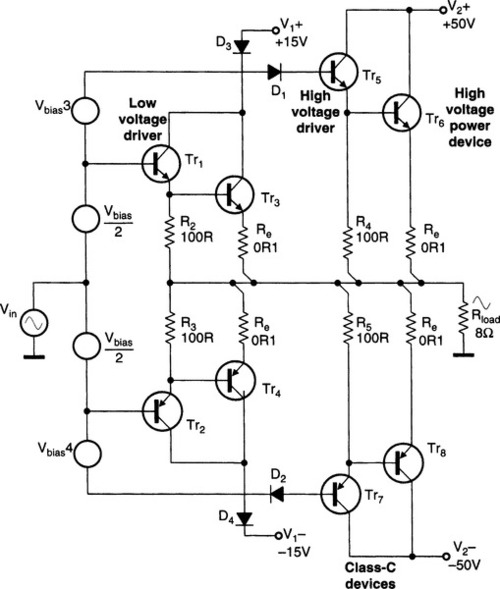
Diodes D3,4 protect Tr3,4 against reverse bias. The conduction periods of the Class-C devices are variable, but much less than 50%. Class-G-Shunt schemes usually have A1 running in Class-B to minimise dissipation, giving B • C; such arrangements are often called ‘commutating amplifiers’.
Class B • C • C
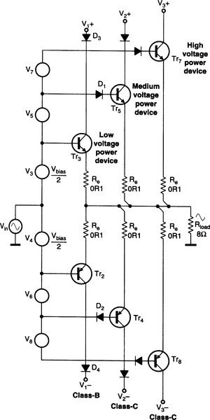
Some of the more powerful Class-G-shunt public-address amplifiers have three sets of supply rails to further reduce the average voltage-drop between rail and output.
The extra complexity is significant, as there are now six supply rails and at least six power devices. It seems most unlikely that this further reduction in power consumption could ever be worthwhile for domestic hifi, but it is very useful in large PA amplifiers, such as those made by BSS. Three letters with intervening dots are required to denote this mode, Figure 4.
Series connection category
In the second group of configurations, voltages are summed by series connection. The intention is usually the reduction of total power dissipation, rather than better linearity.
Since the devices are not usually operating in the same class, two letters are again required for a description, and I have used a plus-sign between them to indicate the series connection.
Class A + B
Figure 5 shows the so-called ‘Super-Class-A’ introduced by Technics in 1978.15 The intention is to combine the linearity of Class-A with the efficiency of Class-B.

The Class-A controlling section A1 is powered by two floating supplies of relatively low voltage, around ± 15 V, but handles the full load current. The floating supplies are driven up and down by a Class-B amplifier A2. This amplifier must sustain much more dissipation as the same current is drawn from much higher rails, but it need not be very linear as in principle its distortion will have no effect on the output of A1.
The circuit is complex and costs more than twice that of a conventional amplifier. In addition, the floating supplies are awkward. This seems to have limited its popularity.
Another A + B concept is the error-correction system of Stochino.16 The voltage summation – the difficult bit – can be performed by a small transformer, as only the flux due to the correction signal exists in the core. This flux cancellation is enforced by the correcting amplifier feedback loop. Complexity and cost are at least twice that of a normal amplifier; Figure 6.

Class A + D
The ‘Super-Class-A’ concept mentioned above can be extended to A + D by running the heavyweight amplifier in the usual high-frequency pwm Class-D configuration.17 Alternatively, an A + D amplifier can be made by retaining the Class-A stage but powering it from rails that switch at audio frequency between two discrete voltages. Recall that this definition of Class-D does not mean high-frequency pwm.
Class B + B
Sometimes called a totem-pole stage to emphasise the vertical stacking of output devices, this arrangement shares the power dissipation between two devices. However, a parallel connection does the same thing more simply and with lower voltage losses.
Class B + B has been used to permit high power outputs from transistors with limited Vceo, but this is rarely necessary with modern devices. The concept is usually regarded as obsolete, Figure 7.

Class B + C
The basic series Class-G with two rail voltages, i.e., four supply rails, as both voltages are positive and negative, is shown in Figure 8. This configuration was introduced by Hitachi in 1976 with the aim of reducing amplifier power dissipation.18,19

Musical signals spend most of their time at low levels, and have a high peak/mean ratio, so dissipation is greatly reduced by running from the lower ± V1 supply rails when possible.
When the instantaneous signal level exceeds ± V1, Tr6 conducts and D3 turns off, so the output current is now being drawn from the higher ± V2 rails, with the dissipation shared between Tr3 and Tr6. The inner stage Tr3,4 normally operates in Class-B, though AB or A are equally possible if the output stage bias is increased.
In principle movements of the collector voltage on the inner device collectors should not affect the output voltage, but practical Class-G is often considered to have worse linearity than Class-B because of glitching due to diode commutation. However, glitches if present occur at moderate power, well away from the crossover region.
Class B + C + C An obvious extension of the Class-G principle is to increase the number of supply voltages, typically to three. Dissipation is reduced and efficiency increased, as the average voltage from which the output current is drawn is kept closer to the minimum.
The inner devices will operate in Class B/AB as before, the middle devices will be in Class-C, conducting for significantly less than 50% of the time. The outer devices are also in Class-C, conducting for even less of the time. Three letters with intervening plus signs are required to denote this.
To the best of my knowledge three-level Class-G amplifiers have only been made in shunt mode. This is probably because in series mode the cumulative voltage drops become too great. If it exists, such an amplifier would be described as operating in B + C + C.
Class B + D
Since the outer power devices in a Class-G-series amplifier are not directly connected to the load, they need not be driven with waveforms that mimic the output signal. In fact, they can be banged hard on and off so long as they are always on when the output voltage is about to hit the lower supply rail.
The outer devices may be simply driven by comparators, rather than via a nest of extra bias generators as in Figure 8. Thus the inner devices are in B with the outer in D. Some of the more powerful amplifiers made by NAD – like the Model 340 – use this approach, shown in Figure 9.

The technique known as Class-H is similar but uses a charge-pump for short-term boosting of the supply voltage. In Figure 10, at low outputs Tr6 is on, keeping C charged from the rail via D.
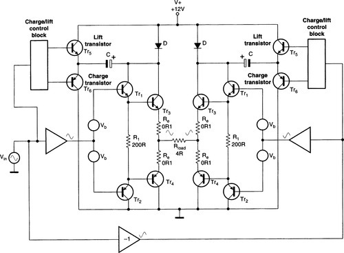
During large output excursions, Tr6 is off and Tr5 turns on, boosting the supply to Tr3. The only known implementation is by Philips20,21 which is a single-rail car audio system that requires a bridged configuration and some clever floating-feed-back to function.
Full circuitry has not been released, but it appears the charge-pump is an on/off subsystem, i.e. Class-D.
In summary
The test of any classification system is its gaps. When the periodic table of elements was evolved, the obvious gaps spurred the discovery of new elements; convincing proof the table was valid.
Table 1 is restricted to combinations that are, or were, in actual use, but a full matrix showing all the possibilities has several intriguing gaps; some, such as C • C and C + C are of no obvious use, but others like A + C are more promising – a form of Class-G with a push-pull Class-A inner stage. Glitches permitting, this might save a lot of heat.
The amplifier table really gets interesting when it becomes clear that there are gaps in the entries – things that could exist but are not currently known.