
8
Aircraft Separation Management Using Common Information Network SAA
8.1 Introduction
Achieving continual safe separation distances between all aircraft, including unmanned aerial systems (UAS), is a critical requirement for integrating UAS and manned aircraft within controlled and uncontrolled airspace. Historically, this has been achieved for manned aircraft in controlled airspace by ground controllers mandating conservative safety volumes and strict flight plan adherence rules. Potential violations of these volumes can be determined if all aircraft in the controlled airspace are being tracked. If the safety volumes are in danger of being violated by an intruder, air traffic control (ATC) officers can request aircraft trajectory adjustments (usually issued by voice commands). This manual process may take from tens of seconds to minutes depending on: (i) the human controller workload; (ii) the ATC service available; (iii) the availability of decision support tools; (iv) the surveillance equipment such as the radar update rate; (v) the number of aircraft in conflict; and (vi) the time it takes for pilots to manually implement changes. This relatively large airspace control latency manifests itself in the application of correspondingly large en-route desired safe horizontal separation distances between aircraft in controlled airspace. A typical value for en-route safe separation is 5 nautical miles, although this value may vary from a few nautical miles near airports to tens of nautical miles for trans-oceanic flights. More recently, the use of an air–ground data link implemented as the Controller–Pilot Data Link Communications (CPDLC) has started to be deployed to reduce the need for relatively slow and routine voice communication between pilots and ATC officers, replacing ATC clearances with data-linked messages. However, this improvement in communications and control latency does not affect the large latencies inherent in the surveillance, manual decision, and implementation process.
Controlled airspace for en-route aircraft is relatively steady state, with aircraft following static flight plans filed prior to departure, and with deviations from these being an exception. When tactical changes are required due to an unforeseen event such as weather, or the deconfliction of a potential loss of separation, the system can adjust in various ways, such as limiting new aircraft departures, re-routing aircraft, or limiting the number of flights within particular sectors.
In uncontrolled airspace there is, typically, no manned ground control authority to monitor safety volumes and, perhaps, no radar coverage. In such airspace, pilots conform to well-known safety rules and safety volumes are self-imposed by a pilot using see and avoid. For UAS operating in uncontrolled airspace, a pilot's see and avoid role would be fulfilled by sense and avoid systems. Standards for these systems are still being researched and developed, but there are no specific standards defining the expected performance (such as conformance to defined separation minima) and guidance behavior resulting from the sense and avoid function. In contrast with controlled airspace, uncontrolled airspace is more dynamic with aircraft crews not required to file and follow a prescribed flight plan. If a threat aircraft is observed or sensed, a pilot can determine and execute the control actions necessary to avoid breaching a loss of separation (LOS) threshold and avoid a potential aircraft collision.
There are two broad categories with regard to sense and avoid (SAA) systems. Here, we define direct sensing as those SAA methods that use onboard sensors to detect local aircraft. We also define networked sensing or network sense and avoid, in which a platform receives information about nearby aircraft via external communication data links. A non-exhaustive list of direct sensing methods includes: (a) pilot visual detection; (b) optical sensor detection; (c) long-wave/forward-looking infrared; and (d) onboard radar. Such sensors allow an aircraft to autonomously detect nearby aircraft. However, these methods suffer from issues including sensor field of view, effective range of detection, and, for certain UAS, there can be severe onboard sizing and weight limitations. Minimal onboard sensing has proven effective for aircraft collision and avoidance maneuvers when a threat aircraft is in very close proximity and emergency action is necessary to prevent a catastrophic collision [1].
Networked sense and avoid occurs when a platform (pilot, ground control operator, and/or onboard flight management system (FMS)) is continually provided with situational awareness and potential threat aircraft data via external communication channels. The networked SAA concept implies the existence of an automated system that maintains aircraft communication links and has access to aircraft tracking data within a region of interest. This tracking data can be monitored and, if a LOS breach is predicted or detected, flight path modifications determined and uplinked to ensure safe separation. In addition to flight plan modifications (and possible other control requests), situational awareness (SA) information can easily be provided to the aircraft pilot and, for potential use by an advanced FMS or a remote UAS operator to decide on suitable avoidance actions.
Networked SAA can help integrate UAS into controlled and uncontrolled airspace by providing separation management information directly to the UAS FMS and/or to the UAS controller. Such an SAA doesn't attempt to provide a vision system equivalent to a human, but rather provides an integrated situation awareness and separation management system applicable to manned and unmanned aircraft. The rationale behind testing networked SAA is supported in the ‘2009–2034 Unmanned Systems Integrated Roadmap’ [2] (A.3.2.3, p. 99), which states that ‘Since the purpose of this regulation [see and avoid] is to avoid mid-air collisions, this should be the focus of technological efforts to address the issue as it relates to UAS rather than trying to mimic and/or duplicate human vision avoiding mid-air collisions’.
One key advantage of networked sensing is that it is straightforward to network aircraft on a communications network using COTS hardware. Table 8.1 lists how networked sensing using persistent communication links to an external network can help overcome several challenges with direct sensing methods for SAA.
Table 8.1 Techniques in which networked sensing can overcome challenges with direct sensing
| Direct sense and avoid challenges | Advantages of networked sensing |
| Aircraft sensor hardware implementation requirements including power, weight, and footprint. | Aircraft communications hardware can be lightweight, low power, and small footprint, including satellite and cellular transceivers. |
| Threat detection problems including threat range and direction of approach. | Tracked aircraft at all ranges and directions. |
| Each sensor is not typically designed with the ability for external communications with other aircraft. | Connectivity with other aircraft and Internet. |
Networked SAA does not preclude the use of onboard target detection sensors on UAS that may augment safety margins. The data from these sensors can also be put on the network as an additional information source.
This chapter explores using networked SAA (in this chapter referred to simply as SAA unless explicitly indicated otherwise) to achieve safe separation thresholds for manned and unmanned aircraft, within a region of uncontrolled airspace using a common information network (CIN). The CIN is assumed to network cooperative airspace users with airspace information sources including an automated separation management process. The work presented here focuses on uncontrolled airspace for the following reasons:
- Controlled airspace has well-established aircraft separation procedures. This work is not a replacement for existing ATM systems and procedures for controlled airspace.
- Many future civil and commercial UAS operations could take place in uncontrolled airspace and at relatively low altitudes. Examples include surveillance, surveying, search and rescue.
- More accidents (specifically, mid-air collisions) with general aviation aircraft, near uncontrolled airports, and under visual meteorological conditions (VMC) [3]. Such airports could be candidates for usage by commercial UAS.
- To ensure safety of all airspace users in the event of future UAS operations in uncontrolled airspace.
Another reason for considering uncontrolled airspace is that civil airspace regulators have plans for implementing next generation ATM systems in controlled airspace which would include a specific implementation similar to networked SAA (NextGen [4] and SESAR [5]). Although developments in automatic dependent surveillance continue, there is at present no agreed way of integrating UAS into these future ATM systems, or of applying these systems to the general aviation community. It is hoped that the research presented in this chapter may help in these efforts.
This chapter will consider uncontrolled airspace in which cooperative aircraft (suitably equipped) share their state information in real time over a network which is connected to an automated separation manager (SM) process. Uncooperative aircraft (those lacking equipment or behaving uncooperatively) are assumed to have their positions tracked by other sensors (such as primary and secondary surveillance radar) and are also present on the network but do not connect with the CIN or the SM process. The SM ensures that safe separation thresholds are achieved for all cooperative aircraft by sending situational awareness data and suggested route deviations for all cooperative aircraft, while accounting for uncooperative aircraft in the suggested deviations.
The rest of this chapter is organized as follows. In Section 8.2 a generic decomposition of aircraft information flow on a CIN is illustrated. A specific implementation of this process for the Smart Skies Flight Test program is described in Section 8.3. Test results from the Smart Skies Flight Tests are given in Section 8.4. Finally, in Section 8.5, possible future uses of this approach are discussed.
8.2 CIN Sense and Avoid Requirements
In this section we present a generic process for information flow on a network-based SAA system on a CIN which continuously monitors aircraft tracks, issues SA information, and, if necessary, computes safe aircraft trajectory modification information. Throughout this chapter we limit our considerations of SAA using automated aircraft separation management performed by a centralized control center. In other words, the control center provides a hub for the airspace separation management system components, including the networked aircraft. This assumption is made so that the SAA process is easily visualized and reflects a system that has been flight tested by the authors. A decentralized and networked SAA system can also be constructed in a similar manner but will not be discussed.
It is advantageous to decompose this information processing and flow in a structured, hierarchical manner [6]. Figure 8.1 illustrates a high-level depiction of a closed-loop SAA information flow on a CIN. The flow contains seven segments. Segment 1, User Data Source, is the process by which current aircraft state data is estimated for an air vehicle and inserted into the CIN. For cooperative aircraft, Segment 1 could be implemented on an aircraft by merely deriving and transmitting GPS onboard navigational data. For uncooperative aircraft, Segment 1 could be implemented by deriving aircraft tracks from a ground-based radar system. In Segment 2, Track Capture, the transmitted data from Segment 1 is captured at a CIN communications node (such as a relay satellite, air-vehicle or ground station) for subsequent relay to a control center. Segments 3, 4, and 5 represent the process and flow at the centralized SAA control center. Segment 3, Estimate True Track, consolidates and extrapolates data received from all Segment 2 sources. Since one aircraft may have multiple sources of state data, any redundant sources must be analyzed, compared, and resolved. The key output from Segment 3 is the best estimate of the present and future track of the tracked aircraft. This output is then used by Segment 4, Determine Control Process, which contains the actual SM algorithm. In Segment 4, present and predicted distances between all aircraft are estimated to determine if specified LOS safety thresholds between aircraft are violated. If any future violations occur, safe trajectory modifications are computed by the SM. In general, LOS violations will be anticipated far enough in the future so that there is ample time for the new trajectory deviations to be transmitted, received, and then executed by the aircraft. However, in cases where a LOS violation is imminent or LOS has already occurred, the SM can declare an emergency (EMER) condition and immediately send a safe (fall-back) maneuver to the aircraft. Segment 4 also includes SA information including aircraft states. Segment 5, Control Routing, within which the SM determines the optimum communication path for the situation awareness data and possible deviations to be sent to the user. These messages are disseminated to the user in Segment 6, Control Dissemination, and then displayed in Segment 7, User Data & Display.
Figure 8.1 SSA information flow on a CIN
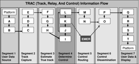
Table 8.2 Information flow segment functions
| Segment | Key functions |
| 1. User Data Source:Prepare and transmit AC state information | A. Prepare aircraft state information for transmission this cycle
B. Transmit information |
| 2. Track Capture:Communication of aircraft information to SAA control center | C. Capture aircraft information
D. Process data stream E. Connect and relay data stream to ground center |
| 3. Estimate True Track:Derive aircraft predicted states from potentially several sources | F. Aggregate information from all aircraft this cycle
G. Integrate, filter, and route received information H. Predict aircraft states using current and historical information |
| 4. Determine Control:Evaluate separation constraints and perform separation management | I. Evaluate separation constraints this cycle over appropriate time windows
J. Determine controls needed to achieve safe separations, perform EMER action if necessary K. Generate situation awareness information for local display L. Prepare controls and SA information for transmission |
| 5. Control Routing:Determine communications path to aircraft | EMER. Prepare and route emergency information
M.Establish routing for nominal transmissions this cycle N. Route nominal transmissions |
| 6. Control Dissemination:Communications to aircraft | O. Establish aircraft connection
P. Capture control center information |
| 7. User Data & Display:Aircraft receives SA and control information and takes appropriate action | Q. Receive SA and control information
R. Process control information S. Integrate all information for decision T. Perform control this cycle |
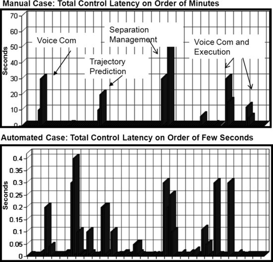
The information flow shown in Figure 8.1 represents a real-time closed-loop control process. The track, relay, and control (TRAC) segments define the individual sub-processes of information flow at a high level. These TRAC segments, in turn, are broken down into 20 segment functions labeled A to T, plus the emergency action EMER function. The segments and associated segment functions are listed in Table 8.2. The purpose of this decomposition is to define and understand critical components in the flow of information on a CIN and to determine key requirements. One key requirement is understanding information latency of SAA on a CIN, which we define as the time necessary for information to flow from Segment 1 to Segment 7. Each segment function in Table 8.2 has an associated latency. If we make the conservative assumption that the flow is sequential, the total latency is simply the sum of the individual segment function latencies. It is interesting to compare the information flow latency for completely manual versus completely automated flows. This is accomplished in Figure 8.2, where a LOS scenario involving several aircraft must be monitored and safely separated. In this figure the x-axis represents the segment functions A–T listed in Table 8.2. The y-axis represents the estimated latency associated with each segment function. Manual control using voice commands between a controller and a pilot is an intensive task, with some cases taking on the order of minutes. The top half of Figure 8.2 indicates the major contributions to the latency resulting from voice communications, the ability to predict and resolve the potential LOS, and the implementation of these new commands (segment functions B, H, I, J, Q, and S). The bottom half of the figure shows how this latency can be reduced to a few seconds by employing data links over a CIN and with computer algorithms performing the critical tasks of estimating future LOS and safe separation deviations. Note that the y-axis in the top graph (manual case) ranges from 0 to 70 seconds whereas the y-axis in the bottom graph (automated case) ranges from 0 to 0.4 seconds. The significant latency peaks for the manual case become negligible for the automated case. These values were derived by estimating the performance of typical HW, SW, and communication performance which suggests that latency on the order of 3 seconds or less is possible with automation.
Figure 8.2 Comparison of latency for manual and automated information flows. The horizontal axis represents the segment functions listed in Table 8.2
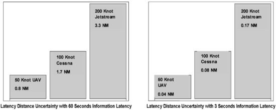
The information latency, dt, is directly related to the separation distance in which aircraft can be safely controlled. An aircraft with speed v will travel approximately dt*v distance from the time aircraft state information is determined in segment function A (prepare aircraft state information) until it implements any appropriate actions in segment functions S and T (integrate information and initiate control action). In dynamic airspace the aircraft can implement changes in states at any time so that prediction of future states will always have a measure of uncertainty related to this latency. Figure 8.3 shows the relationship between latency distance, uncertainty, and information latency for three aircraft speeds. A desired small latency of 3 seconds associated with automated information flow makes the distance uncertainty negligible when compared with a latency of 60 seconds.
Figure 8.3 Comparison of latency distance uncertainties for information latencies of 60 seconds (left) and 3 seconds (right)
8.3 Automated Separation Management on a CIN
8.3.1 Elements of Automated Aircraft Separation
Automated aircraft separation management (SM) is an essential component of SAA on a CIN. SM is a continuous process in which computer algorithms, using information from external communication inputs, evaluate the current and predicted separations between all tracked aircraft to ensure that safety threshold constraints are met. If LOS constraints are violated, the algorithm computes safe deviations from planned trajectories which will satisfy all constraints. These trajectory modifications are sent to cooperative aircraft via the CIN and can either be implemented automatically, or presented for a manual oversight approval process.
The key elements of separation management on a CIN are encapsulated in the segment functions defined for Segments 3, 4, and 5 (shown in Table 8.2). Inputs from all users on the CIN are accomplished by segment functions F (aggregate information from all aircraft this control cycle) and G (integrate, filter, and route received information). These two functions prepare the information received from the CIN for processing by the SM algorithm. The corresponding Segment 5 functions determine which communication paths are best able to transmit data resulting from the SM algorithm to users on the CIN.
The segment functions H (estimate aircraft states using current and historical information), I (evaluate separation constraints this cycle over appropriate time windows), and J (determine controls needed to achieve safe separations, perform EMER action, if necessary) are the key elements of the SM algorithm.
There are several different algorithms used to predict future aircraft states using current (including intent information) and historical state data. For controlled airspace, straightforward methods assume that an aircraft simply follows a predefined geometric flight plan at a known speed. For uncontrolled dynamic airspace, flight plan adherence cannot be assumed, so parameter estimation methods can be used to predict future state, such as: linear extrapolation; closed-form extrapolation assuming constant speed and turning radius; data estimation filters; and trajectory prediction using simplified aircraft models. All methods should, ideally, account for the error in the prediction which will inevitably grow as the look-ahead time increases. This error depends on several factors including the prediction time window, aircraft speed, maneuverability, weather, state data error, and information latency. A simple representation of all possible trajectories in the near future is illustrated by the maneuver cone, an approximate conical volume of potential future aircraft positions. Figure 8.4 illustrates the case where a fast, highly maneuverable aircraft has a much larger maneuver cone than a slow flying UAS. The intersection of the two cones represents potential LOS scenarios. When planning separation maneuvers the SM is aware of the respective speeds of the conflicting aircraft. In the scenario illustrated, the separation strategy leading to the quickest return to safe separations would be to move the fast flyer away from the trajectory of the UAS, because separation can be achieved in a shorter period of time.
Figure 8.4 Intersection of two maneuver cones

Figure 8.5 PDF describing predicted aircraft positions
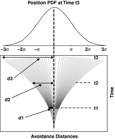
Figure 8.5 shows a probabilistic approach to handling the cone of uncertainty. A probability distribution function (PDF) is estimated for each aircraft position (a Gaussian distribution is illustrated, but typically it will be non-Gaussian). The distribution functions for each aircraft can be compared to derive the probability of a LOS below any desired threshold. The convolution of the two PDFs from two aircraft would give the probability of LOS between the two aircraft at a given position and future time.
Aircraft prediction look-ahead time windows are critical to successful SAA. The time window should be larger than the information latency plus the time it takes an aircraft to execute a safe separations maneuver. The window should not be so large that a large number of false separations result from unreliable predictions. Typical values for general aviation aircraft including UAS range from 10 seconds to a few minutes.
The components of SM involved with anticipating LOS and computing corrective actions are accomplished within Segment 4 by the segment functions I (evaluate separation constraints this cycle over appropriate time windows) and J (determine controls needed to achieve safe separations). There are many categories of SM algorithms [7]. Since we are restricting ourselves to centralized control of aircraft separation, only three categories of automated separation algorithms will be discussed here: grid based, genetic search, and emerging systems.
8.3.2 Grid-Based Separation Automation
An example of a grid-based algorithm could construct a 4-dimensional grid, consisting of three spatial and one time dimension. In this discrete space-time manifold a grid cell at a particular time is either labeled as occupied or not occupied, implemented by using the values 1 or 0 respectively. More advanced grid-based methods can alternatively populate the grid cells with a probability of cell occupation. The occupant of a cell may be considered as a potential threat aircraft or a restricted flight region. Future cell states would be populated as a result of trajectory predictions for a specified look-ahead window. Unoccupied cells within the aircraft maneuver cone represent potential future safe and reachable regions of airspace. The goal of the grid-based algorithm is, when necessary, to ensure that any cooperative aircraft transverses only grid cells with a suitable high probability that the grid cell is unoccupied. Such algorithms can also apply additional logic to ensure that suitable boundary conditions are applied, such as choosing unoccupied cells that safely return an aircraft back to the original flight path. An interesting discussion and application of this approach can be found in the subject literature [8]. A traditional algorithm that has been applied to path planning problems such as this is the A* algorithm [9]. Figure 8.6 illustrates this case.
Figure 8.6 Illustration of grid-based aircraft separation management
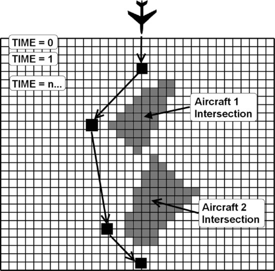
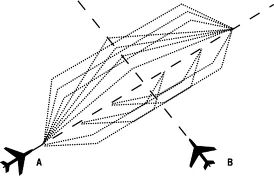
Figure 8.7 Example discretization of the infinite number of solutions to a LOS scenario, as used by a genetic algorithm for automated aircraft separation. Dashed lines represent the nominal flight paths while dotted lines represent a subset of collision avoidance maneuvers for aircraft A
8.3.3 Genetic-Based Separation Automation
An alternative approach is to use a search and optimization technique such as a genetic algorithm (GA) [10]. The goal of one such genetic algorithm [11], which has been applied to aircraft separation, is to discretize the infinite number of solutions to a given predicted loss of separation scenario, as illustrated in Figure 8.7. This is achieved by the a priori creation of a maneuver database that contains numerous trajectory modifications composed of relative heading, altitude, and speed changes (without predefining geographical waypoints). To encode the LOS scenario in a suitable format for use with a GA, many potential solutions, otherwise known as a population, are randomly generated, each with an individual chromosome. Each chromosome consists of the assignment of a trajectory modification to each aircraft involved in the LOS scenario. Determination of the fitness of each solution is achieved by trajectory prediction simulations which test the potential application of the assigned trajectory modification to each aircraft's flight. The fitness of each solution is determined by post-analysis of the ground tracks recorded during the trajectory predictions. Contributing factors for the fitness of each solution include the mutual separation distances between each aircraft during the trajectory prediction, and a measure of the severity that the trajectory modification required each aircraft to deviate off-track. Every generation, the least fit solutions (close separation distances and/or a high track deviation component) are culled, while the remaining solutions are subject to the basic selection, crossover, and mutation genetic algorithm operators. This process is repeated for a specific number of generations or is terminated after a set time limit. Although multiple trajectory predictions are required to test the solutions of each generation, the whole population adapts toward a set of conflict-free trajectories.
8.3.4 Emerging Systems-Based Separation Automation
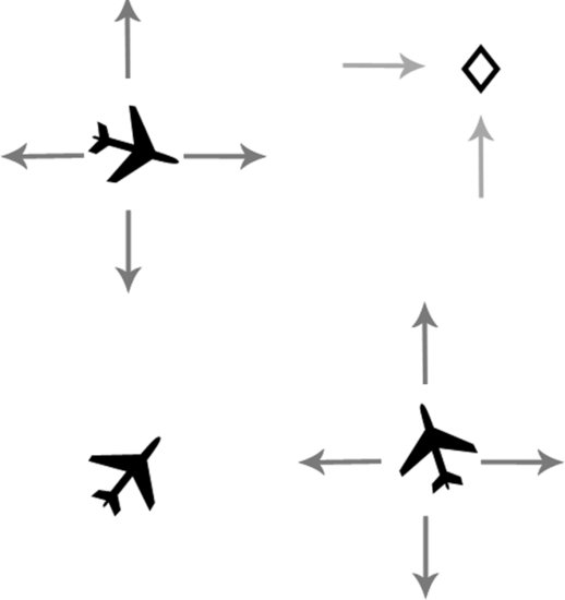
The third approach of interest to the challenge of automated aircraft separation management is based on the inspiration of natural self-organizing systems. Such techniques include artificial potential fields [12--15] and artificial flocking algorithms [16, 17]. On initial inspection, these techniques look ideal for providing neat and simple solutions to automated aircraft separation because they provide dynamic solutions that self-adapt. System order (safe aircraft separation) is achieved by each agent (aircraft) following set rules, with the global solution emerging due to the interaction between the individual agents in the system. In the case of potential fields, each aircraft would emit a virtual repulsive force upon all other aircraft. In theory global order, or safe aircraft separation, should emerge as all the repulsive forces are summed relative to each aircraft. Figure 8.8 illustrates the virtual repulsive forces emitted by each aircraft. In some implementations, aircraft guidance can be provided by applying attractive forces to navigation waypoints (diamond).
Figure 8.8 Simplification of the potential field approach to aircraft separation
In flocking methods, rules are applied to each agent to keep the agents together. When applied to aircraft separation, anti-flocking rules must be generated. In their natural forms, these techniques are perhaps too dynamic and unpractical for application to aircraft separation (unrealistic pilot workloads in dense airspace scenarios). Without modification, the systems tend to oscillate and require frequent heading change commands to be sent to each agent, or aircraft. The authors have tested a restricted version of a hybrid potential field/anti-flocking algorithm [18]. This algorithm created avoidance vectors (determined by summing all the avoidance vectors contributed by involved aircraft) to steer aircraft around zones of potential conflict, yet included simple rules of the air to limit solution oscillation, provide predicable aircraft behavior, and allow overtaking maneuvers. Although results of the algorithm were promising, further testing and integration with typical flight management functions is required.
8.4 Smart Skies Implementation
8.4.1 Smart Skies Background
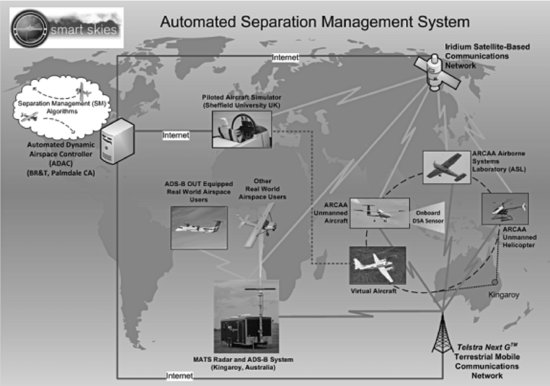
Sections 8.2 and 8.3 outlined the theory of SAA on a CIN. This section discusses a prototype implementation of SAA on a CIN accomplished as part of the Smart Skies Flight Test Project. The Smart Skies Project (Smart Skies) was a 3-year collaborative research and flight test program, which ran between March 2008 and March 2011. Smart Skies explored future technologies that support the safe and efficient utilization of airspace by both manned and unmanned aircraft. The project brought together specialist researchers from Boeing Research & Technology (BR&T) aided by subcontractors at the University of Sheffield, Boeing Research & Technology Australia (BR&TA), and the Australian Research Centre for Aerospace Automation (ARCAA); a joint venture between the Commonwealth Scientific and Industrial Research Organization (CSIRO) ICT Centre, and Queensland University of Technology (QUT). The project objectives [19, 20] were to explore the development of key airspace automation-enabling technologies, one of which was prototyping an automated SAA system on a CIN.
Central to Smart Skies was a series of integrated flight trials conducted at Burrandowan Homestead near the township of Kingaroy in Queensland (QLD), Australia. These flight trials characterized the performance of SAA as envisioned using a CIN, in uncontrolled airspace under realistic and stressing operating conditions. During this program BR&T implemented several automated dynamic airspace control centers (ADAC) which served as SAA centralized control centers for software development, testing, and flight test support. In addition, ARCAA engineers developed and installed custom predictive flight management systems (pFMS) on all test aircraft, which allowed these aircraft to communicate with the ADAC via the CIN. The pFMS accomplishes the key Segment 1 (compiling and transmitting aircraft state) and Segment 7 (receiving and acting on situation awareness and control data) functions of the information flow described in Section 8.2. The pFMS also assists with pilot situational awareness by providing data for cockpit display of traffic information and display of suggested route modifications.
8.4.2 Flight Test Assets
The primary flight test aircraft (illustrated in Figure 8.9) used in the Smart Skies tests included:
Figure 8.9 Flight test assets used during the Smart Skies flight trials. Clockwise from top-left are the ASL, CUAS, flight simulator, QUAS
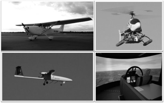
1. A Cessna 172R model aircraft, from here on referred to as the Airborne Systems Laboratory (ASL). The custom modified aircraft is fitted with a GPS-INS truth data system, pFMS, custom navigation display (for visualizing flight plans, flight plan deviations, and other information received from the ADAC such as situation awareness data), and a communications management system. The ASL is capable of conventional human-piloted control or an optionally piloted mode (en-route control only).
2. A small autonomous fixed-wing UAS, referred to as the QUT UAS (QUAS). The QUAS has a maximum take-off weight of 20 kg, a payload capacity of 4 kg, and an endurance of approximately 1 hour (full fuel and payload). Onboard systems include: a pFMS; COTS autopilot; UHF, Iridium and 3G communications; and a vision-based sense and avoid payload.
3. A small autonomous helicopter, referred to as the CSIRO UAS (CUAS). The CUAS has a maximum take off weight of 13 kg and endurance of approximately 45 minutes (full fuel and payload). Onboard systems include: a pFMS; custom-designed flight computer and autopilot; UHF communications; Iridium and 3G communications systems located at the CUAS ground control system.
In addition to the real flight test aircraft described, multiple virtual aircraft were also used to increase the number of aircraft involved in a conflict scenario. A pFMS was developed by the University of Sheffield in conjunction with BR&T which allowed autonomous 6 DOF and piloted flight simulations to communicate with the ADAC over the CIN. These virtual aircraft are provided by the piloted engineering flight simulator [21, 22] or a standalone and fully autonomous 6 DOF flight simulation model developed by researchers at the University of Sheffield. The standalone 6 DOF simulations can be run on low-specification personal computers and are networked to the ADAC via the Internet. Each 6 DOF model uses a simple custom script language to initialize and program desired flight plans. The engineering flight simulator can be piloted and connected to the CIN using the Internet or an Iridium transceiver. From the perspective of the ADAC and the separation management algorithms under test, no distinction is made between the different test aircraft (manned or unmanned, real or simulated). Using simulated aircraft in combination with real aircraft and real communications links provides a safe and efficient testing environment for the evaluation of complex potential LOS scenarios. Virtual aircraft can be safely directed to fly toward real aircraft to force the SM to perform SAA over the CIN. Table 8.3 summarizes the test airspace segment assets which have been used in Smart Skies testing.
Table 8.3 Real and virtual aircraft used for the Smart Skies flight tests
| Real aircraft | Autonomous simulations | Piloted flight simulator |
| ASL – Cessna 172 | Cessna 172 | Cessna 172 |
| CUAS helicopter | Jetstream (twin turboprop) | Jetstream |
| QUAS Flamingo | Flamingo simulation | |
| CUAS simulation |
8.4.3 Communication Architecture
Two independent commercial communication systems were used for the Smart Skies CIN, the Iridium LLC RUDICS system and the Telstra Next G cellular system (NextG). These satellite (Iridium) and 3G cellular (NextG) communication services effectively allowed the ADAC to establish data connections with all aircraft, real and virtual, via TCP/IP Internet connections. The Smart Skies test communication architecture is shown in Figure 8.10.
Figure 8.10 Smart Skies test communication architecture
The use of dual, independent communication channels improves the communication reliability issue for a CIN. Using the well-known formula for combining independent probabilities, P(A) + P(B) – P(A∩B), implies that two independent 90% reliable channels, when used in combination, result in a 99% communications reliability.
This architecture allows multiple aircraft to be continually tracked and controlled from an ADAC located anywhere in the world with Internet access [23]. Note that while the real aircraft were flying in Queensland, Australia, the primary flight test ADAC was located in Palmdale, CA. Execution of the virtual aircraft simulations was distributed between Sheffield, UK and in Palmdale, with the simulations offset to produce ground tracks over the test range in Australia. Typically, all test aircraft flew over the test range and with pre-planned flight plans that would cause various LOS scenarios with both virtual and real aircraft.
The ASL test aircraft could be flown either in a cooperative or an uncooperative mode. A mobile airspace tracking system (MATS) was deployed at the test site which could track real aircraft using radar and an ADS-B receiver. The MATS, which is under development by Boeing Research & Technology Australia, is capable of detecting non-cooperative aircraft over short to medium ranges. This information can then be networked with other surveillance sources to provide situational awareness to a ground controller and/or ADAC. This allowed the ADAC to track uncooperative aircraft over the test range [24]. Note that radar was not being used to provide a collision avoidance system (which implies a last-minute function). Rather, it tracks potential targets which the SM algorithms can account for when generating tactical route modifications.
A more detailed illustration of the Smart Skies ADAC architecture is given in Figure 8.11. This figure illustrates how an Iridium satellite connects to the Internet via the Iridium commercial gateway in Tempe, AZ.
Figure 8.11 ADAC components and connectivity with the Iridium system
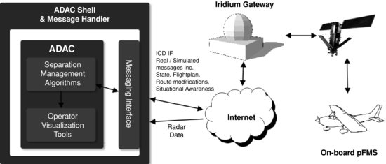
The ADAC consists of several computers distributed on a Local Area Network (LAN) performing the tasks of:
1. Interfacing message traffic to and from users outside the ADAC via a messaging system referred to as the ADAC shell.
2. Aircraft separation management.
3. Operator situational awareness displays.
8.4.4 Messaging System
The ADAC shell was implemented by way of a message handling software component which communicated over the LAN with the SM algorithm. The SM used a network interfacing component (accessed via a dynamic link library) which allowed the development of SM algorithms to be isolated from the details of interfacing with the CIN. The ADAC LAN has a gateway to the Internet, allowing connections with all other nodes on the CIN. Users on the CIN can include both real and simulated aircraft. In this prototype system the ADAC message handling shell provides the role of a messaging server and the cooperative aircraft act as clients. Other ADAC software (such as the SM) can also connect as a client of the messaging server, enabling flexible ADAC configurations. Aircraft join the network by establishing TCP/IP connections with the messaging server and periodically transmitting state vector information and flight plan information. All messages are transmitted with a binary encoding, enabling more efficient usage of data-link bandwidth when compared with pure ASCII messages. In practice, some legacy communication systems require additional encoding of binary data to avoid erroneous insertion of control characters into data streams. This approach has been adopted in this project and all data channels use a consistent encoding scheme to support such legacy systems, regardless of whether the encoding is required by the underlying communication system. In typical use, the airborne pFMS transmits a binary state data message, here termed trajectory array data set (TADS), to the ADAC at a nominal rate of 1 Hz (the actual rate is also a parameter varied for particular tests). The TADS message contains aircraft position, speed, and altitude parameters recorded onboard at a given instant. There are approximately 80 bytes per TADS including message overhead.
The ADAC sends two key messages to the pFMS. Periodically, the ADAC will send a situational awareness message consisting of the position, heading, and altitude of all known nearby aircraft within a given region. If the SM algorithm determines action is necessary to avoid a LOS, the ADAC will send a flight plan route modification to the pFMS. In this project, we term recommended flight plan modifications issued by the ADAC as commanded TADS (CTADS). In the Smart Skies implementation, the following guidance rules were agreed by the Smart Skies researchers for the generation and implementation of the CTADS. Participating real and virtual aircraft conformed to these rules.
1. Route modifications must be terminated at a navigation fix or waypoint coincident with a waypoint on the original flight plan.
2. All waypoints in a CTADS route modification message are considered as fly-by.
3. While navigating a set of CTADS waypoints, pilots should maintain their current speed or alter speed to meet any possible waypoint arrival time constraints.
4. Pilots should attempt to maintain standard rate turns when transitioning between the flight plan legs defined by the CTADS.
5. Pilots should attempt to navigate the CTADS waypoints in sequence and navigate each CTADS leg as if it is a track-to-fix (TF) leg.
6. CTADS flight plan modifications will arrive in advance of the requirement to perform the first maneuver. The ADAC has to account for communication latencies as well as potential latencies occurring while a pilot or automated system reviews and accepts the flight plan modification.
These rules were implemented so that aircraft are not left lost (for example, the creation of flight plan discontinuities, or routing the aircraft far off nominal track) with respect to the ADAC and the onboard aircraft FMS. Although this typically happens when aircraft are vectored by ATC, rejoining with the original flight plan requires manual sequencing of the waypoints. Requiring ADAC-generated flight plan modifications to return aircraft to a point on the original flight plan reduces uncertainty in estimating the location and near-future plan of participating aircraft. With respect to integrating UAS into mixed airspace, reducing such uncertainties contributes to the perception of increasing safety in the system. Restricting aircraft to a particular navigation behavior also reduces uncertainty and improves the accuracy of trajectory predictions computed by the separation management software.
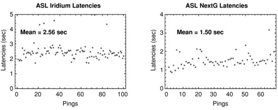
Typically, each aircraft in a flight test maintains an end-to-end connection with the message handling server. Although TCP/IP connections are maintained, the nature of the communications links used in the Smart Skies CIN implementation (Iridium and 3G) means that losses in the connectivity of the wireless data links will tear down the connection with the server. Typically, the physical data-link implementations attempt to keep the connection open even in the event of temporary signal loss. However, the system must compensate for inevitable connection losses. In such situations, the message handling server can be left unaware that a data link has been lost. For this reason, it is the responsibility of the pFMS on each participating aircraft to reconnect with the message handling server. To sense the presence of zombie connections on the message handling server, the transmission of a custom ping message between the ADAC and the pFMS acts as a connection heartbeat. When the server attempts to relay a ping message through a zombie connection, the message handler senses the disconnection and frees any previously allocated resources. The use of a ping message also allows the ADAC to continually monitor CIN latencies with all nodes. Typical latencies measured during flight tests are given in Figure 8.12. The end-to-end information flow latency over the Iridium system is approximately 2.6 seconds, whereas the latency of the cellular NextG was 1.5 seconds. Similar results were observed in each test. Additionally, the standard deviation is greater for Iridium latencies.
Figure 8.12 Example CIN end-to-end latencies over satellite (Iridium) and cellular (NextG) networks
An ADAC/pFMS/CIN interface control document (ICD) listing in detail the content of these messages was established early in the program. The key messages, lengths, and their typical transmission rates are listed in Table 8.4.
Table 8.4 Key messages used to communicate between the ADAC and the pFMS
8.4.5 Automated Separation Implementation
During Smart Skies, the primary SM algorithm tested within the ADAC was developed by BR&T scientist Dr Regina Estkowski. The algorithm, a variation of the grid-based method described in Section 8.3, has been named the Virtual Predictive Radar (VPR) algorithm and is considered Boeing proprietary. The algorithm, which was tailored to meet the requirements of the Smart Skies Flight Test program, and modified several times during the project to implement new requirements, successfully managed and separated aircraft LOS scenarios ranging from 2 to 50 aircraft over the test region. Example use of the previously described genetic algorithm conflict resolver (Section 8.3) and potential field algorithms was also briefly fielded but with more limited test and results. However, the ability to swap-in differing aircraft separation algorithms was considered to be beneficial.
8.4.6 Smart Skies Implementation Summary
Table 8.5 lists the segment level information flow decomposition for networked SAA as implemented in Smart Skies.
Table 8.5 Smart Skies implementation of the information flow segments
| Segment | Smart Skies implementation |
| 1. Source aircraft data | pFMS collects GPS/INS information and transmits to the CIN through dual communication links. Aircraft include ASL, QUAS, CUAS, and virtual 6 DOFS and hands-on simulators. Dual transmissions for all real cooperative aircraft. Uncooperative aircraft tracked by MATS |
| 2. Communications: aircraft to SAA control center (ADAC) | Cooperative real aircraft: simultaneous satellite (Iridium) and cellular transmission via Internet gateways to ADAC
All real aircraft: radar and/or ADS-B transmissions (if available) over Internet to ADAC Virtual aircraft: Internet connections to ADAC |
| 3. Estimate aircraft predicted states within airspace | ADAC message handler receives transmissions over dual channels. SM chooses primary (pre-selected) channel if available. Trajectory predictions are made within the SM using a combination of state extrapolation and aircraft intentions (flight plan) information |
| 4. Evaluate separation constraints and perform separation management | Boeing VPR algorithm uses short-term and long-term separation constraints. When violated it issues appropriate CTADS following agreed upon rules if necessary |
| 5. Choose communications path to aircraft | ADAC SM chooses any good communication link (cellular and satellite) and requests the MH to use the selected channel |
| 6. Communications: SAA control center to aircraft | Same paths as Segment 2 |
| 7. Aircraft receives SA and control information and takes appropriate action | pFMS receives messages, manned aircraft displays SA data, choice of manually controlling ASL using cues or autonomously controlling heading by lateral autopilot
Real UAS and virtual aircraft autonomously implement commands from ADAC |
8.5 Example SAA on a CIN – Flight Test Results
The Smart Skies program consisted of eight separate flight phases, with each phase lasting approximately 3 days, resulting in over 25 flight test days over 2 years. For each flight test with the ADAC, teams were deployed to the test region in Burrandowan, Queensland (ASL, QUAS, CUAS, and MATS teams), Palmdale, CA (ADAC team), and to the Sheffield simulator site in the UK. The early test phases occurring in 2009 had relatively simple aircraft separation scenarios such as that illustrated in Figure 8.13. This figure shows a screen capture of an experimental ADAC visualization tool (SSBDO) and depicts: two aircraft, the ASL (labeled AID 6) and a virtual Cessna 6 DOF (labeled AID 1); their conflicting oval flight plan trajectories; the CTADS automatically issued by the ADAC to achieve a safe separation. For the illustrated test case, the nominal flight plans were developed so that a head-on LOS would occur on the right-hand side of the oval. For this particular scenario the desired minimum separation threshold was defined as 1 km with both the simulated aircraft and the ASL receiving CTADS, indicating that each aircraft shared the cost of the separation maneuver. The resulting distance of closest approach (DCA) while both aircraft were navigating the CTADS route modifications was approximately 1.7 km and the separation was deemed successful.
Figure 8.13 Head-on separation test: the ASL and a virtual Cessna

More complex and operational scenarios were investigated in 2010. Other scenarios examined SM performance as a function of aircraft type, approach geometry, speed, and data rate [25, 26]. Although all results can't be reported, an example of an operational scenario is shown in Figure 8.14. The left-hand side of the figure illustrates a complex fire-drop scenario where the ASL and two additional aircraft are flying trajectories that would enable them to drop fire suppressant on a fire at the lower portion of the figure. Simultaneously, the QUAS (fixed wing) is flying a fire surveillance mission and the CUAS (small helicopter) is simulating a search and rescue mission in the immediate fire zone. The right-hand side of the figure shows a snapshot of the actual test as visualized in SSBDO. In order to further stress the SM, altitude differences between all aircraft could optionally be ignored, with separation based on horizontal distances only. Most scenarios (including the fire-drop test) were planned to have several near simultaneous LOS events and can be seen by the three active trajectory modifications being executed in the right-hand part of Figure 8.14. In this particular scenario, the planned and actual mutual separation distances of the five aircraft for the first 800 seconds of this flight test are shown in Figure 8.15. Each curve in Figure 8.15 represents the mutual horizontal distance in kilometers versus time for a pair of aircraft involved in the test. In this test there are five aircraft giving rise to ten distinct mutual separation curves. The horizontal dashed lines indicate the upper and lower thresholds for safe separation. In the actual test case the SM resolved all but one of the LOS events. The violation occurred with the CUAS rotorcraft UAS and a 6 DOF simulation of a Cessna aircraft. This result illustrates a problem with predicting the short-term trajectory of a rotorcraft which can hover and change heading in a manner very different from a fixed-wing aircraft. Separations between all fixed-wing aircraft were successful for this test.
Figure 8.14 Fire-drop with search and rescue scenario; planned and actual
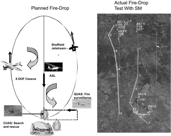
Figure 8.15 Planned (top) and actual (bottom) mutual distances of closest approach between all aircraft plotted against flight trial time for the fire-drop scenario

Over ten additional complex scenarios were also tested during 2010 [27], ranging from tests involving 2 up to 50 aircraft at varying altitudes. Approximately 10% of the tests involved a mixture of cooperative and uncooperative aircraft; the remaining approximately 90% involved only cooperative aircraft. At the time of this publication researchers are still evaluating test results. High-level descriptions of some of the preliminary results are listed in Table 8.6. Four key SM test parameters were: (i) airspace complexity; (ii) platform information content; (iii) received information quality; (iv) and operator obedience response.
Airspace complexity refers to the types of aircraft, aircraft density, and aircraft maneuverability and separation geometries. Platform information content refers to the TRAC flow Segment 1 information characterizing the aircraft state. Received information quality refers to Segment 7 information that is received at the aircraft after traversing the CIN. Operator response obedience refers to how a pilot or ground controller would use the information such as from SSBDO or SA data to make decisions.
Table 8.6 Flight test summary
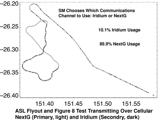
With regard to these four SM test parameters, the SM worked well for various airspace complexities (i). The TADS information set transmitted by cooperative aircraft worked well at data rates between 0.5 Hz and 2 Hz (ii). One research question still being investigated is: under what conditions does having the attitude plus position state information (7D information) provide an advantage over positional information only (4D information)? In general, the information latency on the CIN was less than 3 seconds (iii). When the primary information channel did drop out (manifested either by a large delay in message arrival or a data call disconnection), the SM switched to the backup channel. An example of the SM switching between the primary and secondary CIN communications channels is shown in Figure 8.16. Using commercial communications systems inevitably resulted in instances where poor signal quality communications software interfaces failed onboard the real aircraft, resulting in significant message latencies (>10 s). In general, the ASL test pilots were comfortable using the automated lateral autopilot and permitting the ADAC to directly command the autopilot (through an uplinked and reviewed route modification). One of the prime benefits of permitting the autopilot to guide the aircraft through the ADAC suggested trajectory modifications was that it reduced their workload by reducing head-down concentration while navigating the aircraft in complex scenarios. With regard to the SSBDO operator displays, the belief was that it would reduce ground controller workloads but as yet, this has not been quantified using actual controller inputs (iv).
Figure 8.16 Example of the ASL connected to the CIN by two communication channels. Note how the SM decides from which channel to select data
8.6 Summary and Future Developments
The successful Smart Skies flight test program has demonstrated the feasibility of implementing networked SAA via a CIN with the test architecture described. A description and implementation of a prototype networked SAA system was presented. The Smart Skies flight tests purposely included airspace scenarios, with integrated UAS that were considerably more complicated than one would expect to find in current uncontrolled airspace. Additionally, since UAS were assumed to be fully integrated in the airspace with respect to ATC (as implemented using an ADAC), each type of aircraft was considered as an equal during the airspace management process. The use of COTS communication networks to provide data links was successful. Each flight asset included an implementation of a pFMS that not only enabled aircraft state data to be transmitted, but also provided a multilink interface (in this case Iridium and 3G cellular, but others could be incorporated) to the various autopilots and FMS used in Smart Skies. Information latencies (data acquisition, transmission and reception, and separation control initiation) on the order of a few seconds have been established. The flight tests successfully demonstrated automated airspace management (with integrated UAS) and that aerial platforms can be controlled using trajectory modifications directly from the ADAC, and executed by the pilot (onboard or at a UAS ground station) to avoid loss of separation events between aircraft. Further, in many tests the piloted ASL remained under autopilot and pFMS control during the entire flight (lateral navigation of the nominal flight plan and received route deviations), with only speed and altitude control required by a human pilot. One important achieved milestone was the use of radar data to separate cooperative from uncooperative aircraft and place this information on the CIN.
Although additional research is continuing, it is reasonable to consider and explore issues with networked SAA over CIN for operational use, either exclusively or to complement onboard/direct SAA capabilities. Clearly, any operational system would have to consider key issues such as: affordability; communications reliability with cooperative aircraft; the tracking of uncooperative aircraft; and the multitude of aircraft and FMS/autopilot equipment installed in GA aircraft and UAS. There still remains the need to track uncooperative aircraft and the possibility of not being able to get tracks on uncooperative aircraft if ADS-B or radar information is unavailable. In the case when uncooperative tracks are not available the system would have to rely on current see and avoid procedures.
As mentioned previously, advanced ATM concepts, such as using traffic information services (TIS-B) and ADS-contract from a control center, would represent one implementation of SAA over a CIN. However, questions of affordability for UAS, use within the GA community, and the impact of forcing one solution on all users, have caused much debate on this approach. Ideally, networked SAA on a CIN shouldn't be restrictive to most users, so an option is that UAS should always be suitably equipped and cooperative, while GA and other users can opt out, especially if they are using alternative equipment that can be indirectly placed on the CIN (for example, ADS-B conformant equipment). In such a case, the emphasis would be to deconflict UAS, while other airspace users could opt in. Another approach to allow GA users to opt in, or to provide situational awareness of nearby UAS, is to take advantage of the recent growth in smart phones and smart tablets. Many of these devices have built-in GPS receivers (or the ability to connect to other suitable devices) and attitude sensors and can communicate over cellular and satellite systems with a small cost to the user.
An operational system would also need to resolve the problem of the lack of standardization among the navigational and guidance behavior exhibited by the variety of available FMS. For the Smart Skies implementation, a rigid interface control was adopted by all flight and simulation assets, which would not be possible for an operational system. Currently, a wide variety of FMS/autopilot systems are being used in GA and for UAS navigation, ranging from lateral-only autopilots and simple direct-to navigation systems to full 4D trajectory management computers and adaptations of commercial transport aircraft FMS. It is likely that these systems will produce a large variety of navigational guidance responses to flight plan modifications uplinked by future airspace automation systems. Before UAS can be safely integrated into non-segregated airspace managed by a semi- or fully automated CD&R system, the navigation systems and algorithms must produce predictable responses to uplinked commands [28]. One potential option is to enforce UAS to conform to performance-based navigation principles, with additional agreed guidance rules to conform to while executing uplinked suggested route modifications.
A crucial aspect of networked SAA is that information regarding all airspace users in a specific region is available. Boeing Research & Technology is investigating an approach that would amalgamate and translate the many different formats and communication methods into a common interface to address the problem of diverse platforms and formats on the CIN. Communications over multiple networks, satellite and terrestrial, certainly helps the communication reliability problem. Additional research remains to be accomplished in this area, but initial results using cellular and Iridium are very encouraging.
In summary, the computer hardware and communication network advances over the past decade have made it feasible to consider implementing SAA over a CIN in the near future. Such a system would provide the best-known situation awareness to the pilot in the cockpit with a latency of a few seconds. This additional information, while not guaranteed to be complete, would certainly augment the current method of see and avoid and provide an additional margin of safety.
Acknowledgments
The authors would like to acknowledge Mr Ted Whitley for supervising BR&T's effort in the Smart Skies project. Ted developed the concept of the ADAC and has long been a proponent of automated air traffic control. In addition, the many contributions of BR&T scientist Dr Regina Estkowski are acknowledged. Regina developed the primary separation management algorithm used during the Smart Skies project and, as part of the Smart Skies engineering team, offered invaluable advice, insight, and analysis into making this a successful project. We also acknowledge the advice and support of Professor David Allerton at the University of Sheffield. Further, we acknowledge the members of the Boeing Iridium Support and Battlescape development teams for their detailed subject knowledge and technical support. Finally, we wish to acknowledge all ARCAA members of the Smart Skies team. Headed by Professor Rod Walker with assistance from Dr Reece Clothier, the Smart Skies team has accomplished amazing engineering design and development tasks in a short period of time in order to conduct the airborne flight trials. This project has been funded, in part, by the Queensland State Government Smart State Funding scheme.
References
1. S. Temizer, M. J. Kochenderfer, L. P. Kaelbling, T. Lozano-Pérez, and J. K. Kuchar, ‘Collision avoidance for unmanned aircraft using Markov decision processes’, Proceedings of the American Institute of Aeronautics and Astronautics (AIAA) Guidance, Navigation, and Control Conference, Toronto, Ont., August 2–5, 2010.
2. 2009–2034 Unmanned Systems Integrated Roadmap, US DOD, 2009.
3. R. C. Matthews, ‘Characteristics of U.S. midairs’, FAAviation News, 40(4), 1, 2001.
4. Joint Planning and Development Office, ‘Concept of operations for the next generation air transportation system’, Version 3.0, 2009.
5. SESAR Consortium, Deliverable 3 – The ATM target concept, Document DLM-0612-001-02-00, 2007.
6. The Boeing Company, US Patent 7,212,917: Tracking relay and control information flow analysis process for information based systems, issued and published May 1, 2007.
7. J. K. Kuchar and L. C. Yang, ‘A review of conflict detection and resolution modeling methods’, IEEE Transactions on Intelligent Transportation Systems, 1(4), 2000.
8. O. Watkins and J. Lygeros, ‘Stochastic reachability for discrete time systems: an application to aircraft collision avoidance’, IEEE Conference on Decision and Control, Maui, HI, 2003.
9. N. J. Nilsson, Artificial Intelligence: A New Synthesis, Morgan Kaufmann, 1998.
10. J. H. Holland, Adaptation in Natural and Artificial Systems, University of Michigan Press, 1975.
11. G. T. Spence and D. J. Allerton, ‘A genetic approach to automated aircraft separation’, CEAS 2009, Manchester, UK.
12. M. Eby and W. Kelly, ‘Free flight separation assurance using distributed algorithms’, IEEE 1999 Aerospace Conference, March 14–18, 1999.
13. W. Kelly and M. Eby, ‘Advances in force field conflict resolution algorithms’, AIAA Guidance, Navigation, and Controls Conference, Paper 2000-4360, Denver, CO, August 14–17, 2000.
14. S. Lee and J. Park, ‘Cellular robotic collision free path planning’, 5th International Conference on Advanced Robotics, Vol. 1, pp. 539–544, 1991.
15. O. Khatib, ‘Real-time obstacle avoidance for manipulators and mobile robots’, International Journal of Robotics Research, 5(1), 90–98, 1986.
16. C. W. Reynolds, ‘Flocks, herds and schools: a distributed behavior model’, Computer Graphics, 21(4), 25–34, 1987.
17. G. W. Flake, The Computational Beauty of Nature, The MIT Press, 1998.
18. G. T. Spence, D. J. Allerton, R. Baumeister, and R. Estkowski, ‘Real-time simulation of a distributed conflict resolution algorithm’, ICAS 2008 26th Congress, Anchorage, September 2008.
19. R. Clothier and R. Walker, The Smart Skies Project, AUVSI North America 2009, Washington, DC.
20. R. Clothier et al., ‘The Smart Skies Project’, accepted for publication in IEEE Aerospace and Electronic Systems Magazine, 2011.
21. D. J. Allerton, ‘A distributed approach to the design of a real-time engineering flight simulator’, 21st ICAS Congress, September 1998.
22. D. J. Allerton, Principles of Flight Simulation, John Wiley & Sons, 2009.
23. The Boeing Company, US Patent 7,457,690: Systems and methods for representation of a flight vehicle in a controlled environment, issued and published November 25, 2008.
24. M. Wilson, ‘A mobile aircraft tracking system in support of unmanned air vehicle operations’, 27th International Congress of the Aeronautical Sciences, Nice, France, 2010.
25. R. Baumeister et al., ‘Evaluation of separation management algorithms in class G airspace’, AIAA Modeling and Simulation Technologies Conference, Chicago, IL, AIAA-2009-6126, 2009.
26. R. Baumeister et al., ‘Test architecture for prototyping automated dynamic airspace control’, CEAS European Air and Space Conference, Manchester, UK, 2009.
27. R. Baumeister et al., ‘Automated aircraft tracking and control in class G airspace’, 27th International Congress of the Aeronautical Sciences, Nice, France, 2010.
28. G. W. Flathers, D. J. Allerton, and G. T. Spence, ‘FMS automation issues for future ATM integration’, 27th International Congress of the Aeronautical Sciences, Nice, France, 2010.