CHAPTER 14
Balance Controls
The Ideal Balance Law
The job of a balance control on a preamplifier is to adjust the relative gain of the left and right channels and so alter the position of the stereo image to the left or right and do nothing else at all. As you would expect, increasing the left gain moves things to the left and vice versa. The ideal law is therefore that of a stereo panpot in a mixing console. Two uncorrelated sound sources (and any signal will be uncorrelated once it has left the loudspeakers and bounced around the room a bit) add just like white noise sources and so give a combined signal that is 3 dB higher and not 6 dB higher. The sine/cosine panpot law in Figure 14.1 is therefore appropriate for the balance control of a stereo signal, because the level of the combined signals will not alter as the image is moved across the stereo stage from one side to the other (see panpots in Chapter 22). It is a constant-volume balance control.
I am aware I said in the first edition of this book that the panpot law was not the ideal balance law, so let me clarify that. The sine/cosine law is functionally ideal in terms of its operation but is not optimal in terms of electrical performance. Since the gain is -3 dB at the central position, there will be some compromise. If the 3 dB loss is made up by gain before the balance control, the headroom is reduced by 3 dB. If the loss is made up with 3 dB of gain after the balance control, the noise performance is likely to suffer. The only way to avoid this is to use an active balance control, which alters the gain of a stage rather than passively introducing attenuation.
A panpot in a mixing console reduces one of the signals to zero at each extreme of the pot rotation. There is no need to do this in a preamplifier. A balance control does not have to make radical changes to signal level to do its job. Introducing a channel gain imbalance of 10 dB is quite enough to shift the sound image completely to one side so it appears to be coming from one loudspeaker only, and there is nothing at all to be gained by having the ability to fade out one channel completely.
This means that the ideal balance control is not a mixer panpot as such but a panpot effectively limited in its rotation so that neither end stop is reached and the signal is never reduced to zero. This might be called a truncated sine/cosine law. An example is shown in Figure 14.2, where 20% of the control rotation at each end is not used, and the central 60% spread out to give more precise control. As a result, the maximum attenuation, with the balance control hard over, is -10.4 dB, while the minimum attenuation is -0.41 dB. The attenuation at the centre is unchanged at -3.0 dB; a central detent on a balance control pot is highly desirable.

Figure 14.1 The sine/cosine law for a constant-volume stereo balance control.

Figure 14.2 A truncated sine/cosine law for a constant-volume stereo balance control.
In the case of a switched balance control, this is equivalent to using a 23-way switch (there must be an odd number to give a central position) and calculating it as part of a notional 37-way switch that has the extreme seven positions at each end inaccessible. This gives a greater number of steps over the range in which the control is actually used.
Since the balance control is usually a set-and-forget function that does not require readjustment unless the listening room is rearranged, it is not often considered when controls are being motorised. In fact, getting the balance exactly right by leaping up and down between sofa and preamplifier is rather more tiresome than manual adjustment of volume.
If we look at the issue purely from the point of electrical performance rather than functionality and ignore the desirability of a constant-volume balance control, the ideal balance law would have no attenuation when set centrally and, when moved to left or right will attenuate only one channel without affecting the gain of the other. This can be done with special balance pots that are available from several manufacturers. If there is attenuation at the central position, then it needs to be made up by extra amplification either before or after the balance control, and this means that either the overload margin or the noise performance will be compromised to some degree. As noted earlier, the only way to avoid this is to use an active balance control, which alters gain rather than attenuation.
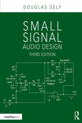
Balance Controls: Passive
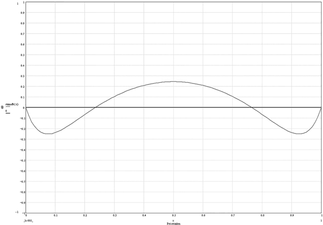
Figure 14.3 shows the various forms of passive balance control; only the right channel is shown in the first three cases. Anti-clockwise movement of the control is required to introduce attenuation into the right channel and shift the sound image to the left. In Figure 14.3a, a simple pot is used. If this has a linear track, it will give a 6 dB loss when set centrally, and when the two uncorrelated stereo channels are rms summed, there will be a 3 dB drop in the centre as the control is moved from hard left to hard right. See Figure 14.4, where no truncation of the balance law is used. This is a long way from being an ideal constant-volume balance control. An extra 6 dB of gain has to be built into the system to counteract the central loss, and the noise/headroom compromise is undesirable. If a log law is used for one channel and an anti-log law for the other, the central loss can be made smaller, say 3 dB or less. Such dual-slope pots are not noted for their accuracy, so the uncertainties of log-law tolerancing mean it will not be possible to guarantee that the channel gains are identical when the control is centralised.
Special balance pots, as shown in Figure 14.3b, have half of each track, including the central position, made of a low-resistance material so that neither channel is attenuated at the central setting. On moving the control clockwise, the right channel wiper stays on the low-resistance section and gain stays at 0 dB, while the left wiper moves onto the normal log/anti-log section and the signal is attenuated. Since there is no central attenuation, the combined signal level falls off at each side; this is not a constant-volume balance control.
The linear control in Figure 14.3a can be much improved by the addition of a pull-up resistor, as in Figure 14.3c, which reduces the attenuation at the central position. With a 10 kΩ pot, a 3.6 kΩ pull-up resistor gives a central drop of very close to -3.0 dB, making the balance law approximately constant-volume.
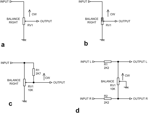
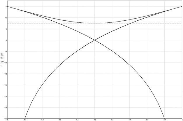
Figure 14.4 The -3 dB central drop in overall volume when a linear balance law is used.

Figure 14.5 Not quite constant-volume when a linear pot with a pullup resistor is used as in Figure 14.3c to approximate the sine/cosine law. Maximum error 0.35 dB.
The result is seen in Figure 14.5; we have the right combined volume at the centre, but the volume is up to 0.35 dB low elsewhere. This is not likely to be perceptible under any circumstances, and we have very simply created what is for all but the most demanding applications a constant-volume balance control.
We can make things even better by reducing the pull-up resistor to 3.0 kΩ, which spreads the volume error out over both sides of the 0 dB line, reducing the worst-case volume error to 0.25 dB, as in Figure 14.6. You might think this improvement is mere pedantry, but if it is possible to make things work slightly better simply by changing a resistor value, I can think of no reason not to do it.
More information on what is essentially a panpot configuration can be found in Chapter 22, though there the emphasis is more on constant volume when panning a mono signal to stereo.
The economical method at Figure 14.3d was once popular, as only a single pot section is required. Unfortunately, it has the unavoidable drawback that the relatively high resistance between wiper and track causes serious degradation of the interchannel crosstalk performance. If the resistance values are reduced to lower Johnson noise, the track-wiper resistance is unlikely to decrease proportionally, and the crosstalk will be worsened. With the values shown, the loss for each channel with the control central is -3.2 dB. This loss can be reduced by decreasing the value of R1, R2 with respect to the pot, but this puts a correspondingly heavier load on the preceding stages when the control is well away from central.
Some preamplifier designs have attempted to evade the whole balance control problem by having separate but concentric volume knobs for left and right channels. The difficulty here is that almost all the time, the volume only will require adjustment and the balance function will be rarely used; it is therefore highly desirable that the left and right knobs are linked together in some sort of high-friction way so that the two normally move together. This introduces some awkward mechanical complications.
Balance Controls: Active
An active balance control is configured so that it makes a small adjustment to the gain of each channel rather than introducing attenuation, so that any noise/headroom compromise can be avoided altogether. Since all active preamplifiers have at least one gain stage, the extra complication is likely to be minimal. It is not elegant to add an extra active stage just to implement the balance function.
Figure 14.7a shows an active balance control that requires only a single-gang pot. However, it suffers from the same serious disadvantage as the passive version in Figure 14.3d; the wiper connection acts as a common impedance in the two channels and causes crosstalk. This kind of balance control cannot completely fade out one channel, as it is not possible to reduce the stage gain below unity, and in fact even unity cannot be achieved with this configuration, because whatever the setting, there is some resistance to ground making up the lower feedback arm. With the values shown, the gain for each channel with the control central is +6.0 dB. With the control fully clockwise, the gain increases to +9.4 dB and decreases to +4.4 dB with it fully anti-clockwise; the range is deliberately quite restricted. It is a characteristic of this arrangement that the gain increase on one channel is greater than the decrease on the other.

Combining Balance Controls With Other Stages
The balance control function is a very simple one; just control attenuation or gain over a rather limited range. I have always felt it is inelegant and uneconomic to design into a system a stage that does that and nothing else.
My earliest attempts in this direction were to combine the balance control with a Baxandall tone control, the balance pot varying the amount of output signal fed to the NFB side of the Baxandall network, with provision for minimising the source impedance variations. This might suggest a bit of approximate technology, but it actually worked rather well, with only a very small amount of interaction between balance setting and tone settings. It is fully described in Chapter 15.
More recently, I have found it expedient to combine the balance control with a balanced (differential) line input amplifier. It is a pity that there are two different uses of the word “balance” in the same circuit block, but there’s not much that can be done about it except to call the line input a “differential input”, which is less common in audio usage. There is more on this combination later in this chapter and in Chapter 18 on line inputs.
Figure 14.7b shows an active balance control combined with an active gain control and mono/stereo switching. This configuration was used in the original Cambridge Audio P-series amplifiers; in that application, A1 was a simple two-transistor inverting stage and A2 an even simpler single transistor. The left-hand section of volume control RV1 is the feedback resistance for A1, while the right-hand section forms part of the input resistance to shunt stage A2, both changing to give a quasi-logarithmic law when the control is altered. The balance control RV2 is a variable resistance in the shunt feedback network of A2. The mono/stereo switch feeds the virtual-earth node of A2 with both channels via R3, R4 when in mono mode. The circuit has two inverting stages and so handily maintains the absolute phase of the output.
Switched Balance Controls
A balance control implemented with a pot is subject to inaccuracy due to the loose tolerances of the pot track (20%) compared with the fixed resistors around it. This does not apply to the arrangements in Figure 14.3a and Figure 14.3b, because here the pot is acting as a pure potentiometer, with its output determined only by the wiper position. (This assumes that the next stage puts negligible loading on the pot.) If Figure 14.3a has a linear track to avoid the inaccuracies of log and anti-log tracks, there is an excessive 6 dB loss when set centrally. The accuracy of the control in Figure 14.3b depends on whether the resistive (non-metal) part of the track is linear or log.
A switched balance control, like a switched volume control, offers more than enough accuracy for even very precise audio work and allows complete freedom in selecting the control law. As for volume controls, the drawbacks are much increased cost and a limited number of control steps. The latter is less of an issue for a balance control, as it can have far fewer steps and still give all the control resolution for image position that is required. As with switched volume controls, the cost of the switch increases steeply with the number of steps. I suggest 24 steps is enough for a truly world-class balance control, and such switches are readily available. One of the switch positions must correspond to the central setting, so we actually need an odd number of switch positions. The 24-way switch is therefore mechanically stopped down to 23 positions, with position 12 being the centre. The switch should be make-before-break to minimise glitching.
Table 14.1 shows a truncated-sine law as described earlier; the maximum attenuation at each extreme is -10.4 dB. This is shown implemented in Figure 14.8.
| Switch
position |
Sine Law
X |
Gain
dB |
RMS summation dB |
|---|---|---|---|
| 23 | 0.9537 | –0.412 | 0.000 |
| 22 | 0.9397 | –0.540 | 0.000 |
| 21 | 0.9239 | –0.688 | 0.000 |
| 20 | 0.9063 | –0.854 | 0.000 |
| 19 | 0.8870 | –1.041 | 0.000 |
| 18 | 0.8660 | –1.249 | 0.000 |
| 17 | 0.8434 | –1.479 | 0.000 |
| 16 | 0.8192 | –1.733 | 0.000 |
| 15 | 0.7934 | –2.011 | 0.000 |
| 14 | 0.7660 | –2.315 | 0.000 |
| 13 | 0.7373 | –2.647 | 0.000 |
| 12 | 0.7071 | –3.010 | 0.000 |
| 11 | 0.6756 | –3.406 | 0.000 |
| 10 | 0.6428 | –3.839 | 0.000 |
| 9 | 0.6088 | –4.311 | 0.000 |
| 8 | 0.5736 | –4.828 | 0.000 |
| 7 | 0.5373 | –5.396 | 0.000 |
| 6 | 0.5000 | –6.021 | 0.000 |
| 5 | 0.4617 | –6.712 | 0.000 |
| 4 | 0.4226 | –7.481 | 0.000 |
| 3 | 0.3827 | –8.343 | 0.000 |
| 2 | 0.3420 | –9.319 | 0.000 |
| 1 | 0.3007 | –10.437 | 0.000 |
| End steps | 7 |

Figure 14.8 A 23-step passive constant-volume switched balance control with make-before-break wiper contact. Position 12 is the centre position.
Mono-Stereo Switches
It was once commonplace for preamplifiers to have mono-stereo switches, which allowed a mono source to be played over both channels of a stereo amplifier system. Most of these were configured so that the two channels were simply joined together somewhere in the middle of the preamp stages, which was not very satisfactory unless the unused input was terminated in a low impedance to minimise noise. More sophisticated switching allowed either the left or the right input only to be routed to both outputs.
Figure 14.9a shows a simple mono switch. As indicated here, it was usually placed just before the balance or the volume control. The value of R1, R2 is a compromise; it should not be too high, as it is loaded by the balance pot, and attenuation is introduced that will have to be undone somewhere else. If too low the path between the L and R inputs will have a low impedance that will excessively load the stages up stream when they are dealing with out-of-phase signal content. Another issue is interchannel crosstalk through the capacitance between the contacts when the switch is open.
The more sophisticated version in Figure 14.9b was very commonly used in Japanese preamplifiers. R1 and R2 are shorted out in stereo operation, so there is no loss of gain, and the impedance at the switch contacts remains low, so capacitance does not cause crosstalk. There is, however, some small loss of gain in mono mode. It uses two switch sections, but since the mono switch was very often a two-pole c/o push switch anyway, there was no economic penalty.
For professional mono compatibility checking, no compromises in gain loss or crosstalk are acceptable. Figure 14.10 shows an active mono-switching stage that avoids these problems. Each shunt-feedback stage sums L and R signals in mono mode. There must be an exact 2:1 ratio of resistors to get the correct gains; 2kΩ and 1kΩ from the E24 series will work well in most cases. If the stage is fed from low impedances, then the capacitances between the switch contacts have no effect. Note the phase inversion that can be inconvenient.


Figure 14.10 Active mono/stereo switching stage. Note phase inversion.
Since almost all modern sources are stereo if not multi-channel, mono-stereo switches are now rarely if ever fitted to preamplifiers. They are, however, still seen on mixing consoles to allow checking of mono compatibility.
Width Controls
Another facility which has always been rare in preamps but is now almost unheard of is the width control. Summing a small proportion of each channel into the other reduces the width of the sound image, and this was sometimes advocated, as a small width reduction would make the image less associated with the loudspeakers and so give a stronger illusion of acoustic reality. This of course runs directly counter to more contemporary views that very high levels of interchannel isolation are required to give a good stereo image. The latter is flat-out untrue; it was established long ago by the BBC in extensive testing before the introduction of FM stereo broadcasting that a stereo separation of 20 to 25 dB is enough to give the impression of full image width.
By cross-feeding antiphase signals, the width of a stereo image can be increased. A famous circuit published by Mullard back in 1972 [1] gave continuous variation between mono, normal, and enhanced-width stereo. It was stated that antiphase cross-feed of greater than 24% should not be used as it would cause the sound image to come apart into two halves. Figure 14.11 shows an up-to-date version that I have used in many mixing console designs, usually on stereo input modules.
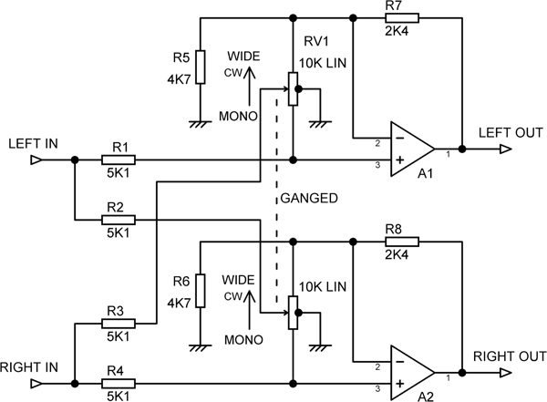
Figure 14.11 Stereo width control, with variation from mono through normal to extra-wide.
With the control central, the stereo width is unaltered, as the cross-feed through R2 and R3 is grounded via the centre-taps of the pot tracks. If there were no centre-taps, we would be relying on the limited mechanical accuracy of the dual pot to minimise the cross-feed, and this would not work well. With the pot fully anti-clockwise, 100% of each channel is summed with the other, giving mono. With the pot fully clockwise, a fraction of each channel is summed with the other in anti-phase, increasing stereo width. The pot should have a centre-detent to positively indicate the “normal” position.
Reference
[1] Rose, M. J., ed Transistor Audio and Radio Circuits 2nd edition. Mullard, 1972, p 180