CHAPTER 16
Mixer Architecture
Introduction
A large mixing console arguably represents the most demanding area of analogue audio design. The steady advance of digital media demands that every part of the chain that takes music from performer to consumer must be near perfect, as the comfortable certainty that everything will be squeezed through the quality bottleneck of either analogue tape or vinyl disc now looks very old-fashioned.
The technical problems that must be overcome in a professional mixing console are many and varied and often unique to console design. A large number of signals flow in a small space, and they must be kept strictly apart until the operator chooses to mix them; crosstalk must be exceedingly low.
There may be 72 input channels or more, each with many stages that all have the potential to add distortion and noise to the precious signal. Even summing these signals together, while sounding trivially easy, is in practice a major challenge. The quality requirements, especially for recording consoles, are much more demanding than those for the most expensive hi-fi equipment, because degradation introduced at this stage can never be retrieved.
Performance Factors
Two primary requirements of modern consoles are very low noise and minimal distortion. Since a comprehensive console must pass the audio through a large number of circuit stages (perhaps over 100 from microphone to final mixdown), great attention to detail is essential at each stage to prevent a build-up of noise and distortion; one of the most important trade-offs is the impedance of the circuitry surrounding the opamp, for if this is too high, Johnson noise will be increased, while if it is too low, an opamp will exhibit non-linearity in struggling to drive it.
The choice of opamp is also critical, for cost considerations discourage the global use of expensive ICs. In a console with many stages of signal processing, this becomes a major concern; nonetheless, it is possible to keep the right-through THD below 0.002% at 20 dB above the normal operating level so that at normal levels it is unmeasurable.
I will use the term mixer, mixing console, and mixing desk interchangeably where it will make the text less clunky. In the USA it is sometimes called simply “the board”. I hope I can put “mixer” without anyone thinking I am referring to the front end of a radio or a kitchen appliance, or indeed anything concrete related. Throughout this chapter the various sections of the mixer –the channels, groups, master, etc., will be referred to as “modules”, even if they are not constructed as separate physical modules.
In hi-fi, the preservation of absolute phase has only recently come to be considered necessary; with normal listening material, it appears highly unlikely that it actually makes any audible difference, but it unquestionably looks good on the spec. In mixer design, the meticulous preservation of phase is a rigid requirement to avoid the possible cancellation of signals. Both summing amplifiers and most EQ sections use shunt feedback and thus invert the signal, and it is sometimes necessary to include inverting stages that do nothing but get the phase straight again. It is a mark of good design to keep such stages to a minimum.
Mixer Internal Levels
The internal signal levels of any mixing console are always a compromise between noise and headroom. A higher level means that the signal is less compromised by circuit noise but makes inadvertent overload more likely and vice versa. The levels chosen depend on the purpose of the console. If you are recording, you only have to get it right once, but you do have to get it exactly right, i.e. with the best possible signal-to-noise ratio, so the internal level is relatively high, very often -2 dBu (615 mVrms), which gives a headroom of about 22 dB. In broadcast work to air, you only have one chance to get it right, and a mildly impaired signal-to-noise ratio is much preferable to a crunching overload, especially since the FM or DAB channel has limited noise performance anyway, so the internal levels are considerably lower. The Neve 51 Series broadcast consoles used –16 dBu (123 mVrms), which gives a much increased headroom of 36 dB at the cost of noise performance. At least one manufacturer has used balanced mixing buses to reduce the impact of the lower internal levels on signal-to-noise ratio.
As a sidelight on this issue, I might mention a mixer design I worked on some years ago. The decision was taken (no, not by me) to use an internal level of -6 dBu instead of the usual -2 dBu to improve headroom in live situations, the assumption being that 4 dB greater internal noise would go unnoticed. It most certainly did not, and vociferous complaints during beta-testing led to a rapid redesign to convert it back to the old -2 dBu level. Fortunately, we were ready for this one, and the design had been arranged so that the internal level could be altered simply by changing resistor values.
An internal level of -2 dBu does have one unique advantage: doubling the level, as is done by most forms of balanced output stage, gets you directly to the professional +4 dBu level.
Mixer Architecture
A mixing console has a number of input channels that can be summed into groups, and these groups are again summed into a stereo mix as the final result. Small mixers often have no groups and mix directly to stereo.
The structure and signal flow of a mixing console depends very much on its purpose. A recording console needs track return sections to allow the creation of a monitor mix so that as a track is recorded, those already done can be played back at roughly the same levels they will have in the final mix; this is essential so new material can be synchronised with that already in existence. While it is quite possible to use a recording-oriented console for PA work, the reverse is much more difficult and usually impractical.
A sound-reinforcement (PA) console does not need monitor sections, so it can be somewhat simpler, but it typically is fitted with a large number of effects returns. The output from a PA console at a large event is not likely to be in stereo –there will be multiple speakers, each of which requires an individual feed with different equalisation and delay requirements; often there is a centre output.
In PA work, there are often two mixers. The front-of-house (FOH) mixer usually resides in the middle of the audience or in a control-room at the back. If the mixer is in the audience, the less room it takes up the better, as it is occupying seats that could have been paid for. Size is also very much an issue for mixers intended for installation in a control-room, as access to these is often cramped and difficult.
The second type of PA mixer is the so-called monitor mixer. PA work makes much use of “monitors”, i.e. small speakers, often wedge-shaped, that are placed close to the musician so that they can hear their output clearly without straining to pick it out of the main mix. Creating these foldback feeds on a separate mixer where basically each channel consists of a bank of aux sends (from 12 to 32 may be available) gives much greater flexibility than relying on the relatively few aux sends available on the FOH desk. The inputs to the monitor mixers are taken from the inputs to the FOH console by a splitter box, usually transformer based, at the stage end of the “snake” cable to the FOH console. Traditionally, monitor mixers were placed just out of sight at the side of the stage so that disgruntled performers could signal to the hapless monitor engineer that the foldback mix was not to their liking. The widespread adoption of intercoms has given more flexibility in monitor desk placement.
Broadcast consoles are more specialised in their layout, and no one expects to be able to use them for recording or PA applications.
Recording consoles come in two different formats. The first and more traditional is called a split, separate-group, or European-style arrangement and has input channels arranged in one bank, typically to the left of the master section, with the groups banked to the right of it; on a large console, there may be a further set of channels to the right of the groups.
The second format is called the in-line arrangement and has the channels and groups built into the same module. Normally there is a row of channel/group modules to both the left and right of a central master section. In-line consoles are more compact and make more efficient use of the electronic facilities, but they are conceptually more complex and somewhat harder to use. They are not popular in PA work, where you need to do things quickly in real time without juggling a block diagram in your head.
In the sections that follow, we will look at the internals of generic mixers that do not follow any particular design but are configured to bring out as many instructive points as possible.
The Split Mixing Architecture
Figure 16.1 shows the basic arrangement of a split (separate-group) mixer.
Its design is oriented to recording, but like many small- and medium-sized mixers, it could also be used effectively for PA work.
Each channel has both a microphone and line-level input, with a wide-ranging gain control. Once it has been raised to the nominal internal level of the console, the signal is processed by the equalisation section, controlled in level by the channel fader, and then routed to a group or pair of groups or directly to the stereo L-R bus. The position of the channel signal in the overall stereo image is set by the panoramic potentiometer (universally known as a panpot) that controls the proportion of the signal sent to left and right. The channel also has auxiliary send controls that feed the channel signal to the auxiliary buses; sends taken off before the fader are called pre-fade and are normally used for foldback, i.e. helping the musician hear the sound they are producing. Sends taken off after the fader, so their level is dependent on the fader position, are called post-fade sends and are normally used for adding effects such as reverberation that are expected to vary in level with the original signal.
The final feed from the channel to the buses is the pre-fade-listen (PFL); when the PFL switch is pressed, the pre-fade channel signal is sent to the master module via the PFL bus, where it automatically replaces the normal stereo mix feed to the control-room monitor (CRM) loudspeakers.
The group/monitor modules contain both the group section and one or two monitor sections. The group consists of a summing amplifier that collects together all the signals sent to its group bus and passes it to the outside world via a fader and an output amplifier. When recording, this group signal is sent to one track of the recording machine. The monitor sections allow tracks that are already recorded to be played back to the stereo mix bus via a level control and a panpot so that a rough idea of what the final mix will sound like can be set up as early in the recording process as possible. One of the monitor sections will be switchable between the group output and the track return so the monitor mix can be made up of tracks that are being recorded as well as those which have already been laid down. This group/track switching is not shown in Figure 16.1 to aid clarity, but it is fully shown in Figure 16.4. Lack of space means that the monitor return sections usually have only simple EQ or none at all, but they almost always have a pre-fade aux send for foldback purposes. A post-fade send is also extremely useful, as the rough monitor mix is much more convincing if reverberation can be added as appropriate; this is called “wet” monitoring. The monitor sections often each have a PFL switch.
When recording is finished, and mixdown begins, the full facilities of the channels are required, and so the track return signal is now sent to the channel line input and the channel routed to the stereo mix bus. This is often a connection normalled through the line input jack so that the input amplifier receives the track return signal at all times unless a jack is inserted. Back in the days of tape machines, this facility was called “tape normalling”, but now “track return normalling” describes it rather better. The monitor sections in the group/monitor modules are now no longer needed, but since they are routed to the stereo mix bus, they can be used as extra effects returns.
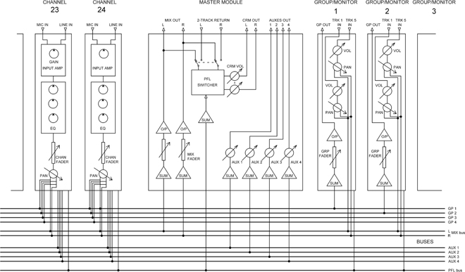
Figure 16.1 Block diagram of a split-format mixer with four groups and four aux sends.
The master section contains the summing amplifiers for the stereo mix bus, which feed a stereo fader and suitable output amplifiers. These provide the final feed to the two-track recording device at mixdown. Normally this stereo output is also sent to a pair of meters and the control-room monitor (CRM) loudspeakers, the latter via a volume control, but the meters and CRM speakers can also be switched to monitor the return from the two-track recorder. When any PFL switch on the console is pressed, this is detected, and the PFL signal (in mono) is fed to the meters and CRM speakers instead, so the signal quality and level from any channel can be assessed.
The master section also contains the summing and level controls for the aux send buses and may also incorporate talkback facilities and a line-up oscillator; these features are dealt with in more detail later in this chapter.
The In-Line Mixing Architecture
Figure 16.2 shows the basic arrangement of an in-line mixer, essentially intended for recording. There are now no group/monitor modules, their functions being performed by what might be called channel/group/monitor modules. Only four group buses are shown for clarity, but in practice, there would normally be a much higher number to make use of the in-line format.
The group summing amplifier is now part of the channel. It no longer has its own fader; instead, the summing amp gain is controlled by a rotary “bus trim” control so overload can be avoided. This is normally placed out of the way at the very top of the module. The group signal is sent out to the recording machine, and the track return comes back in, usually via a balanced amplifier. A Track/Group switch SW2 selects either the group or the track return signal for the metering and the monitor path; as shown in the figure, it consists only of a monitor fader and a monitor panpot, which send the signal to the stereo mix bus to create a monitor mix. The monitor fader is normally a short fader mounted on the channel, as opposed to the long channel fader, which is right at the front of the console. Sometimes a rotary monitor fader is fitted.
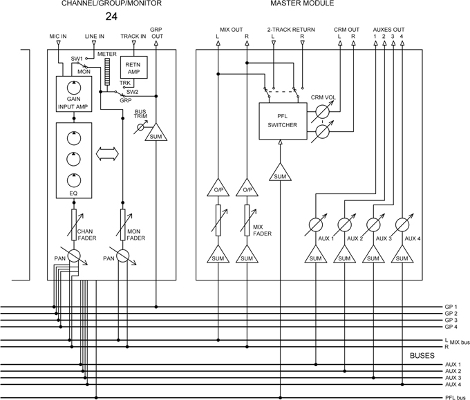
Figure 16.2 Block diagram of an in-line mixer with N groups and four aux sends.
There are two slightly differing approaches to the operation of an in-line module:
- In the first approach, at mixdown, switch SW1 now selects the track return signal rather than the line input, and the signal reaches the stereo mix bus via the full facilities of the channel. Sometimes additional switching allows the monitor path to be used as an extra effects return, as in split consoles. Typically the line input jack is pressed into service as the input connector for this purpose.
- An alternative design approach is not to switch the source of the channel path to the track return at mixdown but instead to move the whole EQ section from the channel to the monitor path. This means that the short monitor fader would have to be used for level adjustment, which is not ideal when there is a long fader right in front of you. This has particular force when fader automation is fitted, for it is normally only applied to the long fader. A switch called “fader flip” is therefore fitted, which swaps over the function of the two faders, allowing the long fader to be used at mixdown. This sort of approach involves a lot of reconfiguration when switching from record to mixdown mode, and on the more sophisticated consoles, this is handled entirely by electronic switching, with global control from the master section, so that only one switch need be pressed to change the console mode. This second method always seems to me to be unnecessarily complex, but it has seen extensive use.
- The master section shown in Figure 16.2 is identical to that shown for the split console in Figure 16.1.
A Closer Look at Split-Format Modules
We will now look in more detail at the channel, group, and master modules that make up a split mixing console.
The Channel Module (Split Format)
Figure 16.3 shows a typical input channel for a relatively simple split-format mixing console. The input stage provides switchable balanced mic and line inputs; the mic input has an impedance of 1–2 kΩ, which provides appropriate loading for a 200 Ω mic capsule. If a +48 V phantom power facility to power microphones is provided, it is independently switchable on each channel. The line input will have a bridging impedance of not less than 10 kΩ. The mic preamplifier in particular will have a wide range of gain, such as 0 to 70 dB, while the line input tends to have a more restricted range such as +20 to -10 dB. The track return from the recording machine is shown connected through to the line input via the normalling contact of the line jack socket so that mixdown with the full channel facilities can begin as soon as the mic/line switch is set to “line”, so long as no jack has been inserted into the line input to break the normalling contact. The line input is shown as unbalanced in Figure 16.3 for clarity, but in practice, it would usually be a balanced input using the tip and ring connections of the jack socket.
The input stage is followed immediately by a switchable high-pass filter (usually -3 dB at 100 Hz) to remove low-frequency disturbances picked up by the microphone as soon as possible; if not filtered out, these can eat up headroom. The filter is usually second or third order, giving a roll-off of 12 or 18 dB per octave, respectively.
The tone-control section (universally known in the pro audio business as “EQ” or equalisation) typically includes one or more mid-band resonance controls as well as the usual shelving Baxandall-type high and low controls. On all but the simplest mixers, the EQ section can be switched out to allow before/after comparisons.

Figure 16.3 Block diagram of a typical channel module for a small mixer.
The larger and more sophisticated consoles incorporate dynamics sections into each channel. This is not shown in Figure 16.3 to aid clarity. The dynamics facilities available vary but usually include compression, limiting, and sometimes noise gating; some consoles have been produced with just the noise-gate function, as it is easier to fit the required electronics into a limited space. A perennial problem with this sort of thing is finding panel room for the extra controls required; the permissible length of a module is limited by the reach of the human arm.
Next comes the insert point, though in some designs it may be configured so it can be placed ahead of the EQ and dynamics section instead. This is a jack or pair of jacks that allow external processing units to be plugged into the signal path. When nothing is plugged in, the “normalling” contacts on the jack socket allow the signal to flow through unchanged.
The PFL (pre-fade-listen) switch routes the post-insert signal to the master module and the monitor speakers independently of all other controls; a PFL-detect bus signals the master module to switch the studio monitoring speakers from the normal stereo mix bus to the PFL bus.
Next in the chain comes the channel on switch. This may be either a simple mechanical switch or an electronic mute block. Note the PFL feed is taken off before the ON switch so the channel signal is always accessible. The channel level in the mix is controlled by a linear fader with a post-fade amplifier typically giving 10 dB of gain, and the panpot sets the stereo positioning, odd group numbers being treated as left and even as right.
The channel shown has three auxiliary sends. The auxiliary sends of a console represent an extra mixing system that works independently of the main groups; the number and configuration of these sends have a large effect in determining the overall versatility of the console. Each send control provides a feed to a console-wide bus; this is centrally summed and then sent out of the console. Sends come essentially in two kinds. Pre-fade sends are taken from before the main channel fader and are therefore independent of its setting. Post-fade sends take their feed from after the fader so that the send level falls or rises according to the fader setting.
Pre-fade sends are normally used for “foldback”, i.e. sending the artist a headphone feed of what he/she is perpetrating, which is important if electronic manipulation is part of the creative process and essential if the artist is adding extra material that must be in time with that already recorded. In the latter case, the existing tracks are played back to the artist via the pre-fade sends on the monitor sections.
Post-fade sends are used as effects sends; their source is after the fader so that the effect will be faded down at the same rate as the untreated signal, maintaining the same ratio. The sum of all feeds to a given bus is sent to an external effects unit and the output of this returned to the console. This allows many channels to share one expensive device, such as a high-quality digital reverb, and for this sort of purpose is much more appropriate than patching processors into the channel insert points.
There may be anything from 1to 12 or more sends available. In the example shown, the first send (Aux 1) is a dedicated pre-fade send, which is typically used for foldback. The third (Aux 3) is a dedicated post-fade send, typically used for effects such as reverb. The second send (Aux 2) can be switched so it is either pre- or post-fade. In a recording console, the greatest need for foldback sends is during track laying, while effect sends are in greatest demand at mixdown; it is therefore common for some or all of the sends on a channel to be switchable pre- or post-fade.
On more sophisticated consoles, it is often possible to switch every auxiliary send between pre and post to give maximal flexibility. Traditionally, this meant pressing a switch on every input module, since it is most unlikely that a mixture of pre and post sends on the same bus would be useful for anything. On a 64-input console, this is a laborious process. More advanced designs minimise the effort by setting pre/post selection for each auxiliary bus with a master switch that controls solid-state pre/post switching in each module. An example of this approach is the Soundcraft 3200 recording console.
Effect Return Modules
In complex mixdowns it may be necessary to return a large number of effects to the mix. While, as described earlier, it is often possible to press unused monitor sections or channel modules into service as effect returns, sometimes this just does not provide enough, and specialised “effects return” modules may be fitted. These usually have facilities intermediate between channels and monitor sections, and it is common to fit two and sometimes even four into the space occupied by a channel module. The returned effect, which may well now be in stereo, such as the output of a digital reverb unit for example, is usually added to the stereo mix bus via level and pan controls.
The Group Module
Figure 16.4 shows a typical group module for a recording desk. Each mix bus has its own summing amplifier; the summed group signal is then sent to an insert so external processing can be applied. The insert send is very often arranged for ground-cancelling operation, for the simple reason that the summing amp inherently phase inverts the signal, which must be returned to the correct polarity by another amplifier stage before it meets the outside world. This second stage can be arranged to be ground cancelling at minimal expense. The operation of ground-cancelling outputs is described in Chapter 19.
The signal from the insert return goes to the group fader. Like that of the channel, it is a linear fader with a post-fade amplifier typically giving 10 dB of gain. The signal then goes to an output amplifier suitable for driving the recording device, possibly via lengthy cables. On all but the cheapest designs, this is a balanced output.
The second major function of the typical group module is to allow the creation of a monitor mix so that as a track is recorded, those already done can be played back at roughly the same levels they will have in the final mix; this is obviously essential to allow new material to be synchronised with that already in existence. Back in the days of tape recording machines, the monitor playback had to be done by the record head, as the playback head was physically displaced and so would have given a delayed signal; this meant the quality of the monitor mix was compromised, as the record head was optimised for recording and not playback. With digital recording, this is of course not a problem.
The monitor section typically consists of a balanced line input to prevent ground-loop problems with the recorder, some form of switching between the group and recorder return, so the track being recorded can be incorporated into the monitor mix and level and panpot controls. EQ is not often fitted for reasons of space, but aux sends for foldback and effects are standard, because adding reverb to the monitor mix makes it much more realistic. A PFL switch for each monitor section is usually provided.
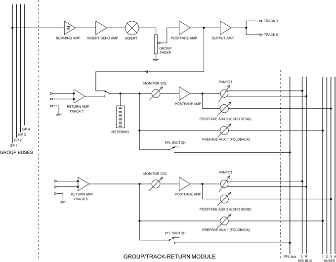
Figure 16.4 Block diagram of a typical group module for a small recording mixer.
Normally relatively few tracks are recorded at a time, so it is sensible to have more monitor sections than groups. For example, a four-group mixer can be very effectively used with an 8-track recorder if Group 1 is connected to Track 1 and Track 5, Group 2 is connected to Track 2 and Track 6, and so on. The track to be recorded is selected at the recorder. To make use of this, each group module will contain one actual group section and two monitor sections, which explains why there is not normally room for even basic EQ in the monitor sections.
The Master Module
Figure 16.5 shows the basics of a typical master section. It contains the summing amplifiers for the stereo mix bus, with their associated insert send amplifiers and insert points. This is followed by a stereo fader (sometimes implemented as two mono faders with the knobs mounted immediately next to each other), a +10 dB post amp, and a balanced or ground-cancelling output stage which feeds the two-track recorder during mixdown.

Figure 16.5 Block diagram of a typical master module for a small mixer.
The stereo mix bus normally drives the L-R meters and the control-room monitor (CRM) loudspeakers, but a manual source-select switch allows this feed to be replaced by the return signal from the two-track recorder for quality checking of the final stereo recording. Whenever a PFL switch anywhere on the console is pressed, the PFL-detect system responds and activates two solid-state switches that replace the stereo monitor signal with the PFL signal. The L-R meter feeds are taken off after the PFL switching so those meters can be used to check the level at whichever point in the system the PFL switch in question happens to be.
The master section also contains the summing and level controls for the aux send buses. The auxes may have dedicated meters or just a PFL switch each.
The master module will also carry any master status switches for globally changing things such as group/recorder switching for the monitor sections, pre/post operation of auxes, and so on.
Talkback and Oscillator Systems
The talkback system allows the mixing engineer to talk to the musicians in the studio or add spoken comments to the recording using a microphone mounted on the console. Back in the day, it was considered cool to mount the talkback microphone on a flexible gooseneck, but these get in the way, and the modern approach is to have a small electret microphone mounted flush with the master module panel.
For talkback to the studio the microphone feed is routed to the aux buses, on the assumption that one or more of these will be in use for foldback and so will be connected to a loudspeaker in the studio area. Routing may also be provided to a dedicated talkback loudspeaker. In many cases, there is a facility to route to the first two auxes only, as these will almost certainly be used for fold back purposes; see the typical system in Figure 16.6.
For recording, identification the microphone feed is routed to the group buses. This facility, which allows the engineer to identify a recording by saying something like “Spinal Tap –take 147” is often called a “slate” facility by analogy with the film industry.
When the talkback facility is used, there is a danger of acoustical feedback. If a microphone in the studio is active and routed through channel and group to the control-room monitors, the monitor speaker output will be picked up by the talkback microphone, fed to the studio … and away she goes. It is therefore normally arranged that pressing any of the talkback switches will attenuate or completely cut the monitor speaker signal. On larger consoles the amount of attenuation (or “dim” as it is usually called in this context) is adjustable.
If the talkback microphone is mounted in the master panel, the distance between it and the engineer will vary as he moves. More sophisticated consoles sometimes incorporate a talkback compressor to reduce the level variations.
Many of the larger recording consoles include a “Listen” facility whereby the control room can hear messages from the studio even if no microphone channels are faded up. A microphone is mounted somewhere out of the way (often suspended from the ceiling) and is routed to the monitors when the “Listen” switch is pressed.
Most mixers of medium size and above incorporate a line-up oscillator which can be routed to all the groups and the stereo mix. This allows the mixer metering to be lined up with external level indication on the recorder. A fixed frequency oscillator running at 1 kHz with a variable output level is the minimum facility; more advanced models have switched or fully variable frequency controls.
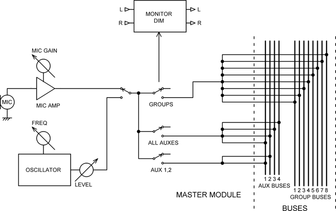
Figure 16.6 Talkback and oscillator system with routing to aux and group buses.
In the typical talkback/oscillator system of Figure 16.6, the line-up oscillator is shown sharing with the talkback system the bank of mix resistors that inject signal into the buses. On a large console, this is quite a lot of resistors, and it would not be sensible to design them in twice. The only compromise is that it is not possible to use talkback and the oscillator at the same time, but then why would you want to? The default selection is talkback, because this is used much more frequently than the oscillator.
The In-Line Channel Module
Figure 16.7 shows a typical channel/group/monitor module for an in-line mixing console. This uses the first approach to in-line operation described earlier, where to enter mixdown mode, the source of the channel path is switched to the track return rather than bodily moving the EQ and other facilities into the monitor path.
The group fader no longer appears. More usefully, the summing amplifier gain can be varied by a rotary “bus trim” control to prevent overload; it is highly desirable that this control alters the gain of the actual summing amplifier rather than having a low-gain summing amplifier with a level control and post amplifier following it, because the former gives greater protection against clipping and superior noise performance at low gain settings. The bus trim is rarely altered, so it can be conveniently be placed out of the way at the very top of the in-line module. The group signal from the summing amplifier is sent out to the recording machine, usually by means of a balanced or ground-cancelling output stage to prevent ground loops occurring with the multi-track recorder. The track return usually comes back via a balanced amplifier for the same reason. A Track-Return/Group switch selects either the group or the track return signal for the metering and the monitor path; as shown in the figure, this path consists of a monitor fader (the “short fader”) and a monitor panpot, which send the signal to the stereo mix bus to create a monitor mix. Note that every in-line module will have a meter, though it is not usual to provide meters for every channel on a split console. A monitor PFL switch is provided so that an individual track return or group can be conveniently listened to.
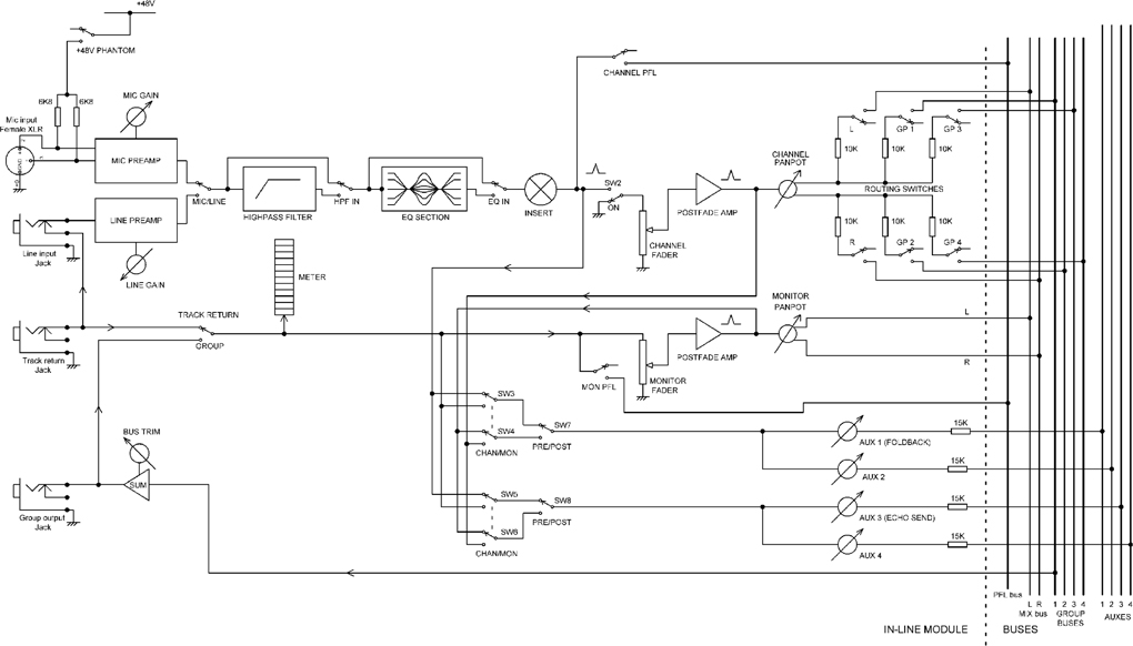
Figure 16.7 A channel/group/monitor module for an in-line recording console.
As in split consoles, it is convenient to connect the track return to the channel line input through normalling contacts on the line input jack, so switching to mixdown requires the minimum number of operations. As described earlier, in this form of in-line configuration, the monitor path is redundant, as the channel fader and panpot are used to control the signal coming back from the multi-track recorder, and so there is usually a way in which the monitor path can be used as an extra effects return, as is commonly done in split consoles. Typically, the line input jack is used as the input connector for this purpose; alternatively, an extra insert point may be provided in the monitor path, into which an external line signal can be fed. These arrangements are not shown in Figure 16.7, which is quite complicated enough already; it is one of the drawbacks of the in-line system that it is conceptually more complex than the split console format.
The auxiliary send system is slightly more complex in an in-line module in the interests of maximum flexibility of working. In the example shown, the sends can be switched in pairs to take their signal either pre- or post-fade from either the channel or monitor path. This is implemented by means of the switches SW3–SW8. For example, during recording, the effect sends can be switched to be monitor post-fade, allowing wet monitoring. Many variations on this aux send are possible; on larger consoles, there will be six or eight sends, and sometimes a stereo aux send with its own panpot is provided.