CHAPTER 17
Microphone Preamplifiers
Microphone Types
There are many ways to make a microphone [1], but for our purposes, there are three main types:
- The dynamic microphone, which consists of a diaphragm that moves a coil of wire in a strong magnetic field. Output -80 to 0 dBu, the higher level only occurring when you put a microphone inside a bass drum. Phantom power is not required.
- The capacitor microphone, where the diaphragm forms one plate of a capacitor with a constant charge applied via a very high value resistor –typically 10 GΩ (yes, 1000 MΩ, a specialised part) so that variations in the capacitance cause voltage variations. There will be a head amplifier built into the microphone body that brings the output up to about the same as a dynamic mic, i.e. -80 to 0 dBu. Dynamic and capacitor microphones can therefore use the same input amplifiers. Phantom power is required.
- The ribbon microphone, where the diaphragm is in the form of a very thin corrugated conducting ribbon in a strong magnetic field; it is essentially a dynamic mic with a single conductor instead of a coil. They have traditionally been regarded as delicate and very vulnerable to damage, as the ribbon is typically about 50 times thinner than the diameter of a human hair, but modern materials have helped somewhat with this. Ribbon microphones are ferociously expensive, costing thousands of dollars. Early ribbon mics were hefty items because of the need for permanent magnets weighing up to 6 pounds (2.7 kg). The introduction of powerful neodymium magnets has allowed modern ribbon mics to be much lighter and more compact.
The output from the ribbon is very low (50–100 μV), and a step-up transformer is often used to get a usable level; a typical sensitivity (with transformer) would be -50 dBu/Pa (2.4 mV/Pa). The output impedance from the transformer is usually around 200–300 Ω, which works well with the inputs used for dynamic and capacitor microphones. A head amplifier is sometimes also built into the microphone to give further amplification and reduce the output impedance. In this case, phantom power is required.
Microphone Preamplifier Requirements
A microphone preamplifier is a serious design challenge. It must provide a gain variable from 0 to 70 dB or more to amplify deafening drumkits or discreet dulcimers, generate minimal internal noise, and have a high-CMRR balanced input to cancel noise pickup in long cables. It must also be able to withstand +48 V DC of phantom power suddenly applied to its input while handling microvolt signals.
It is now rare to use input transformers to match a low-impedance (150–200Ω) microphone to the preamplifier, since the cost and weight penalty is serious, especially when linearity at low frequencies and high levels is important. Both dynamic and capacitor microphones have a low output impedance of this order, the former because of the low number of turns used in the coil, the latter because active buffering of the extremely high capsule impedance is essential.
The low-noise requirement rules out the direct use of opamps, since their design involves compromises that make them at least 10 dB noisier than discrete transistors when faced with low source impedances. The answer, for at least the last 30 years, has been to use hybrid input stages that combine discrete input transistors to give low noise, combined with opamps to provide raw open-loop gain for linearisation and load-driving capability.
To summarise the requirements of a microphone preamplifier:
- Variable gain, usually from 0 to +70 dB. Some designs have a gain range extending to +80 dB. The bottom 20 dB section of the range is often accessed by switching in a 20 dB input attenuator.
- Minimal noise. Taking the source impedance of a microphone as 200Ω, the Johnson noise from that resistance is -129.6 dBu at 25°C, 20 kHz bandwidth. This puts an immediate limit on the noise performance; if you set up 70 dB of gain, then the noise output from the preamplifier will be -59.6 dBu even if it is itself completely noiseless. Most mic preamplifiers approach this at maximum gain, often having a noise figure as low as 1 or 2 dB but depart from it further and further as gain is reduced. In other words, the noise output does not fall as fast as it would if the preamp was noiseless, because reducing the gain means increasing the effective resistance of the gain control network, so it creates more Johnson noise.
- The input must have a high common-mode rejection ratio (CMRR) to reject interference and ground noise. The CMRR should ideally be high, be flat with frequency, and remain high as the input gain is altered over the whole range. In practice, CMRR tends to worsen as gain is reduced. Because of the need for a balanced input, microphone inputs are almost always female XLR connectors.
- The input must have a constant resistive input impedance of 1 to 2 kΩ, which provides appropriate loading for a 200Ω dynamic microphone capsule. This is also a suitable load for the internal head amplifiers of capacitor microphones.
- The input must be proof against the sudden application (or removal) of +48 V DC phantom power. It must withstand this for many repeated cycles over the life of the equipment.
Transformer Microphone Inputs
For a long time, transformer microphone inputs were the only real option. The cost and weight of a mic input transformer for every channel is considerable, especially at the quality end of the market, because a large transformer core is needed to handle high levels at low frequency without distortion. Because of the low signal levels, mumetal screening cans were normally used to minimise magnetic interference, and this added to the cost and weight.
Step-up ratios from 1:5 to 1:10 were used, the higher ratios giving a better noise performance but more difficulties with frequency response because of the greater capacitance of a larger secondary winding. The impedance reflected to the input depends on the square of the step-up ratio, so with a 1:10 transformer, the secondary had to be loaded with 100 kΩ to get the desired 1 kΩ at the primary input.
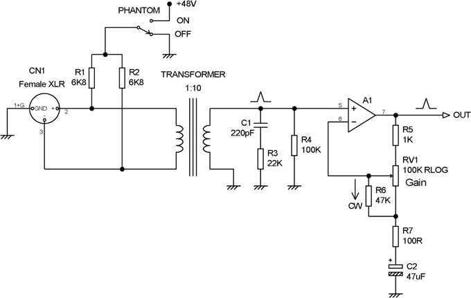
Figure 17.1 A transformer microphone preamplifier. Gain range +20 to +80 dB.
The arrangement in Figure 17.1 has an amplifier gain range from to 0.3 to 60 dB, to which is added 20 dB from the transformer ratio of 1:10, giving +20 to +80 dB of overall gain. R6 in conjunction with the reverse-log pot shapes the control law so it is roughly logarithmic. R4 is the 100 kΩ secondary loading resistor, and C1, R3 form a Zobel network to damp the secondary resonance. In the mid-seventies, when opamps were still a dubious proposition for quality audio, the input amplifiers were very often discrete transistor stages using four or more transistors. Note R5, which prevents the gain from being reduced to exactly unity. Its presence is testimony to the fact that the discrete preamplifiers were difficult to stabilise at HF if the output and inverting input were directly connected together. R1 and R2 feed in phantom power when the switch is in the ON position.
Microphone transformer technology had and still has its own advantages. A balanced input with a good and constant CMRR was inherent. The step-up ratio, which gave “gain for free” in electronic if not financial terms, and the associated impedance matching, meant that it was easy to design a quiet input stage. Transformers also gave good RF rejection and isolated the input preamplifier from phantom power voltages. For EMC reasons in particular, transformer microphones continued in use in broadcast mixing consoles long after they had disappeared from recording and PA equipment.
The Simple Hybrid Microphone Preamplifier
The cost incentive to develop an effective low-noise transformerless microphone input was considerable, and after much experimentation, the arrangement shown in Figure 17.2 became pretty much standard for some years, being extensively used in mixers around the period 1978–1984. (In this period, the more expensive consoles stuck to transformer microphone amplifiers.) The difficulties of getting the noise low enough and the linearity good enough were at first formidable, but after a good deal of work (some of which I did), such stages became almost universal. Q1 and Q2 work as common-emitter stages, with the gain-control network R5, RV1, C3 connected between the emitters. As the resistance of this network is reduced, the differential gain increases, but the common-mode gain remains low. The two signals at the collectors are then summed by the opamp. This does not have to be a low-noise type, because the gain in the transistors means it is they which determine the noise performance, and the TL072 was almost universally used in this position, being at the time much cheaper than the 5532. With appropriate choice of transistors (a type with low Rb) and collector current, preamplifiers of this type can give an equivalent input noise (EIN) of -128 dBu at maximum gain, equivalent to a noise figure of only 1.2 dB with a 200 Ω load. The EIN rises as gain is reduced, because the resistance of the gain-control network and its Johnson noise is increased. The noise output still falls as gain is reduced, but not as fast as the gain.

The gain law is very non-linear with Rg; (=R5 + RV1) a reverse-log D-law pot helps, but there is still some cramping of the calibration at the high gain end, and preamplifier gain ranges of more than 50 dB are not really practicable with this simple arrangement.
Today, this approach is considered obsolete for anything except budget mixer purposes because of its mediocre distortion performance. You will note that the input transistor pair have no overall feedback loop closed around them, and their nonlinearity creates significant distortion, especially at high gains.
The two reverse-biased diodes in the transistor collector circuits are to prevent the opamp being damaged by having its input driven below the -17 V rail when phantom power was applied or removed. Note that the input coupling capacitors C1, C2 shown here are not intended to cope with the phantom voltage if used. On arriving at the input XLR, the microphone signal first encounters the phantom feed resistors, DC blocking capacitors (usually rated at 63 V), a switchable 20 dB attenuator, and possibly a phase invert switch that swaps over the inputs before it reaches the preamplifier. This is illustrated below in Figure 17.4.
The Balanced-Feedback Hybrid Microphone Preamplifier (BFMA)
The microphone preamp architecture described in the previous section has the merit of simplicity, but because there is no global feedback loop around the input transistors, its distortion performance falls far short of the rest of a mixer, which typically consists of pure opamp circuitry with very low distortion. It is obviously undesirable practically, aesthetically, and in every other way for the very first stage in the signal chain to irretrievably mess up the signal, but this is what happened for several years. In the mid-1980s, I decided to do something about this. Many methods of applying feedback to the input stage were tried but foundered on the fact that if feedback was applied to one of the transistors, the current variations in the other were excessive and created distortion. The use of two feedback paths in anti-phase, i.e. balanced feedback, was my solution to this problem; this meant that one feedback path would have to be via an inverting amplifier with extra phase shifts that might imperil HF stability.
The basic concept is shown in Figure 17.3. Direct negative feedback to Q2 goes through R12, while the inverted feedback passes through the unity-gain inverting stage U1:B and goes through R11 to Q1. The gain-control network R5, RV1 and C3 is connected between the two feedback points at the Q1, Q2 emitters and sets the closed-loop gain by controlling the NFB factor. Distortion is pretty much eliminated, even at maximum gain.
The solution to the stability problem is to make sure that the direct HF feedback through C10 dominates that through C12, which has been through the inverter U1:A; this is aided by adding C4 to the inverter to control its HF response. This feedback is therefore not symmetrical at extreme HF, but this has no effect on the functioning of the circuit with audio signals.

Figure 17.3 The balanced-feedback microphone amplifier, known to its friends as the BFMA.
The closed-loop gain is given by Equation 17.1, which looks complicated but becomes clearer when you appreciate that the terms in brackets simply represent the parallel combination of the emitter resistor Re (R1, R2 in the figure) and half the resistance of the gain control network Rg. Rnfb is the value of R11, R12. The 2 on the bottom comes from the fact that we are only using one output of the amplifier –there is an inverted output from the inverter which could be phase summed to give twice the gain. We don’t do that because it is desirable to have as low a minimum gain as possible. With the values shown, the gain range is +22 to +71 dB, which in conjunction with a switchable 20 dB pad gives a useful total range of about 0 to 70 dB.
In order to get enough maximum gain with reasonable values for R5 and C3, the feedback resistors R11, R12 have to be quite high at 82 kΩ. This means that the control of the DC level at the output is not very good. To solve this, the DC servo integrator U2:A was added; R13 is connected to the preamplifier output, and the integrator acts via the non-inverting input of the inverter opamp to keep the output at 0 V.
This technology was used on several consoles, such as the Soundcraft TS12, and later appeared in the Yamaha GA 24/12 and GA32/12 mixers in 1998, a very sincere form of flattery. It had a relatively short life at Soundcraft, as I came up with something better: the padless microphone preamplifier described later in this chapter.
Microphone and Line Input Pads
Microphone pads, or attenuators, are used when the output is too high for the mixing console input to cope with; this typically happens when you put a microphone inside a kickdrum. Attenuators are also used when for reasons of economy it is desirable that the microphone input doubles up as a line input.
A typical arrangement is shown in Figure 17.4. The preamplifier has a typical gain range of +20 to +70 dB. There is an input XLR and phantom feed resistors R1, R2. C1 and C2 are DC blocking capacitors to stop the phantom voltage from getting into the preamplifier; these should be as large as possible to preserve LF CMRR. Next comes a 20 dB balanced attenuator made up of R3–R6; note that the loading of the preamplifier input resistor R10 must be taken into account when designing the attenuator resistor values; one of the functions of this resistor is to prevent the preamplifier input from being open-circuited when the pad switch SW1 or the mic/line switch SW2 is between contacts. C3 and C4 are two further DC blocking capacitors, which prevent the input terminals of the preamplifier, which are not in general at 0 V, from causing clicks in the switching. C5, C6, and C7 increase EMC immunity and also keep the preamplifier from oscillating if the microphone input is left open-circuit at maximum gain. Such oscillation is not an indication that the preamplifier itself is unstable; it normally happens because the insert jacks, which carry the output signal from the preamplifier, are capacitively crosstalking to the microphone input, forming a feedback loop. Ideally the microphone input should be open-circuit stable not only with the input gain at maximum but also with full treble boost set up on the EQ section. This can be challenging to achieve, but it is possible with careful attention to layout. I have done it many times.
In line mode, the microphone gain is of course much too high, and the usual practice is to use a 30 dB attenuator on the line input, which allows a high input impedance to be set by R7, R9 while R8 provides a low source impedance to minimise preamplifier noise. This pad alters the gain range to -10 to +40 dB, which is actually too wide for a line input, and some consoles have another switch section in the mic/line switch, which reduces the gain range of the preamplifier so that the overall range is a more useful -10 to +20 dB. The larger and more expensive consoles usually have separate line input stages which avoid the compromises inherent in using the microphone input as a line input.
There is an important point to be made about the two attenuators. You will have noticed that the microphone attenuator uses four resistors and has its centre connected to ground, whereas the line attenuator uses a more economical three resistors with no ground connection. The disadvantage of the three-resistor version is that the wanted differential signal is attenuated but the unwanted common-mode signal is not, and so the CMRR is much worsened. This does not happen with the four-resistor configuration because the ground connection means that both differential and common-mode signals are attenuated equally. There is no reason the line attenuator here could not have been designed with four resistors; I just wanted to make the point.
The microphone amplifiers described have a high CMRR, and a problem with attenuators like this is that both types degrade the overall CMRR quite seriously because of their resistor tolerances, even if 1% components are used.
The Padless Microphone Preamplifier
The ideal microphone preamplifier would have a gain range of 70 dB or thereabouts on a single control, going down to unity gain without the inconvenience of a pad switch. It was mentioned in the previous section that resistive pads degrade the overall CMRR and also the noise performance as an inevitable consequence of following a 20 dB pad with an amplifier having 20 dB of gain. In addition, space on a channel front panel is always in short supply, and losing a switch would be very welcome. I therefore invented the padless microphone preamplifier. Looking at the mixer market today (2019), the idea seems to have caught on.
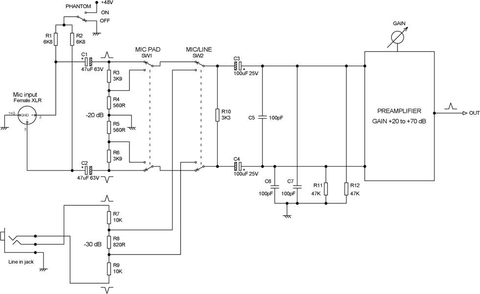
Figure 17.4 Mic and line attenuators at the input of a preamplifier.
The concept is based on the balanced feedback mic amp described earlier, but now the total gain is spread over two stages to give a smooth 0–70 dB gain range with the rotation of a single knob.
The first stage shown in Figure 17.5 is based on the BFMA circuit in Figure 17.3, but with the feedback resistors reduced to 2k7 to reduce the gain range. The gain-control network R5, RV1, and C3 has also been halved in resistance to reduce Johnson noise, and the net result is a gain range of +1.5 to +49 dB; as before, a reverse-log D-law pot is used. The lower feedback resistors mean that no servo is required to correct the DC conditions. Note that the greater amount of NFB means that under overload conditions, it is possible for the common-mode range of the opamp to be exceeded, leading to the well-known TL072 phase reversal and latchup. This is prevented by R11, D3, and D4, which have no effect on linearity in normal operation.

Figure 17.5 The padless balanced feedback microphone preamp: mic input stage.
The second stage of the padless mic amp is shown in Figure 17.6. This consists essentially of a variable-gain balanced input stage as described in Chapter 18, configured for a gain range of 0 to +20 dB. The gain pot is once again a reverse-log D-law pot, and the combination of the gain laws of the two stages gives a very reasonable law over the almost 70 dB range, though there is still a little cramping at the high-gain end.
The second stage is also used as a line-input stage with a gain range of -10 to +20 dB. The mic/line switching used to do this may look rather complex, but it does a bit more than simply change sources. In Figure 17.6, switch SW1 is shown in the line position. In ‘mic’ mode the first stage reaches the inverting input of the second via SW1-B; the output of the mic amp can be phase inverted simply by swapping over its inputs. Line input resistors R1, R2 give reduced gain for line input working, and in mic mode, they are shorted together by SW1-A to prevent crosstalk from line to mic, which is an important issue when track-normalling is incorporated; see Chapter 16. In several of my designs these resistors were placed on the input connector PCB rather than in the channel, to keep their hot ends away from other circuitry and further reduce line to mic crosstalk. SW1-C shorts the junction of R1, R2 to ground, further improving mic/line crosstalk if the line input is not balanced. In mic mode SW1-D shorts the unused second stage non-inverting input to ground.

Figure 17.6 The padless balanced feedback microphone preamp: mic/line switching and second stage.
In line mode, R1, R2 are connected to the second stage via SW1-B and SW1-C. In mic mode; SW1-D shorts R8 to ground so that the gain range of the second stage is increased to the required 30 dB. SW2 is a phase invert switch that simply swaps over the input connections to the second stage.
The padless mic amp gives both a good gain control law and lower noise at low gain settings. The noise performance versus gain for a typical example can be seen in Table 17.1; as described earlier, the EIN and noise figure worsen as the gain is turned down, due to the increased resistance of the gain network. A noise figure of 30 dB may appear to be pretty dire, but the corresponding noise output is only -98 dBu, and this will soon be submerged in the noise from following stages.
This effect can be reduced by reducing the impedance of the feedback and gain control network. This increases the power required to drive them, and because of the square root in the Johnson noise equation, a reduction by a factor of 10, which would need some serious electronics, would only give a 10 dB improvement, and that at the low gain end where it is least needed. Specialised outboard mic amps with low-resistance feedback networks driven by what are in effect small power amplifiers have been developed but do not seem to have caught on.
Another advantage of the padless approach is that one pair of DC blocking capacitors suffices, rated at 63 V as in Figure 17.5, and this improves the CMRR at low frequencies. The padless microphone preamplifier concept was protected by patent number GB 2242089 in 1991 and was used extensively over many ranges of mixing console.
| Gain dB | Noise out dBu | EIN dBu | Noise figure dB |
|---|---|---|---|
| 1.4 | –98.2 | –99.6 | 30.0 |
| 6.6 | –95.4 | –102.0 | 27.6 |
| 15.4 | –90.5 | –105.9 | 23.7 |
| 31.7 | –83.1 | –114.8 | 14.8 |
| 44.1 | –77.5 | –121.6 | 8.0 |
| 51.8 | –72.7 | –124.5 | 5.1 |
| 60.6 | –65.7 | –126.3 | 3.3 |
| 69.3 | –58.7 | –128.0 | 1.6 |
Capacitor Microphone Head Amplifiers
A capacitor capsule has an extremely high output impedance, equivalent to a very small capacitor of a few picofarads. It is in fact the highest impedance you are ever likely to encounter in the audio business and certainly the highest I have ever had to deal with. For this reason, there is invariably a head amplifier built into the microphone body; it has a modest amount of gain, which makes the microphone output level compatible with dynamic mic preamplifiers, as described earlier. Special circuit techniques are required to combine low noise and high impedance, working with a strictly limited amount of power. A while ago, I designed the electronics for a new capacitor microphone by one of the well-known manufacturers, and the circuitry described here is a somewhat simplified version of that.
The first point is that the microphone capsule had an impedance of about 5 pF, so to get a -3 dB point of 10 Hz, the total load impedance has to be no more than 3.2 GΩ (yes, that’s 3200 MΩ). The capsule needs to be fed with a polarising voltage through a resistor, and the head amplifier needs a biasing resistor. In this design, both were 10 GΩ, which means that the input impedance of the amplifier itself had to be not less than 8.9 GΩ. Resistors with these astronomical values are exotic components that come in a glass encapsulation that must be manipulated with tweezers –one touch of a finger and the insulation properties of the glass are fatally compromised.
Figure 17.7 shows my capacitor mic head amp. R1 supplies the capsule polarising voltage, and R2 biases the first stage, a unity-gain JFET source-follower augmented by opamp U1:A, which provides the gain for a high NFB factor to linearise Q1. The drain of Q1 is bootstrapped via C3 to prevent local feedback through the gate-drain capacitance of the JFET from reducing the input impedance. R3, R5, R6 set the DC conditions for Q1.
The second stage is a low-noise amplifier with gain of +4 dB, defined by the ratio of feedback resistor R17 to R15 and R16. Like the first stage, it is a hybrid design that combines the low noise of low-Rb transistor Q2 with the open-loop gain and load-driving capability of an opamp.
The stage also acts as a unity-gain follower, making up a second order Butterworth Sallen and Key high-pass filter when C6, C7 or C8, C9 are switched in; the resistive elements are R10 and R14.
The system has two steps of attenuation: -10 and -20 dB. The first 10 dB step is obtained by using SW1:B to take the output from the junction of R15 and R16 instead of the normal stage output. The second 10 dB-step results from switching C2 across the mic capsule, forming a capacitive attenuator that reduces the input to the first stage and prevents overload. The gains available are thus +4 dB, -6 dB, and -16 dB. The maximum sound pressure handling is +146 dB SPL, or +155 dB SPL with the -20 dB pad engaged.
The incoming phantom power is tapped off by R20, R21 and fed to a discrete BJT regulator that gives +32 V to power the opamp and +14 V to run a small LC oscillator that pumps the +32 V rail up to the +63 V required to polarise the capsule. Total current consumption is 2.2 mA.
The noise output is -120.7 dBu (A-weighted), which may appear high compared with the moving-coil microphone amplifiers described, but remember that a capacitor microphone puts out a high signal voltage so that the S/N ratio is actually very good. The mic capsule, being a pure reactance, generates no noise of its own, and the noise output comes only from the Brownian motion of the air against the capsule diaphragm and from the electronics. A larger-diameter capsule means lower noise because more energy is absorbed from the coherent sound waves; the same applies to the Brownian motion, but this partially cancels, just as with the use of multiple opamps for low noise. [2]

Noise measurements of this technology require special methods. The impedances are so high that meaningful results can only be obtained by putting the circuitry inside a completely closed metal screening enclosure.
Ribbon Microphone Amplifiers
The output directly from a ribbon in its magnetic field (often referred to as the ribbon motor) is of the order of 50 to 100 microvolts (-86 dBu to -77.8 dBu). The level is inversely proportional to the ribbon mass and in directly proportion to the magnetic field strength. Ribbon width varies from 1 to 6 mm. Microphone amplifiers rarely have more than 70 dB maximum gain, so to get the signal up to a usable level, a step-up transformer with a ratio of between 1:25 and 1:40 is used. Compare microphone amplifiers that have a transformer; there the ratio is rarely as high as 1:10. Ribbon mic transformers have more in common with moving-coil cartridge transformers, which also handle microvolt signals. Both have high step-up ratios and are often double shielded to keep out hum; see Chapter 10 for more details.
Ribbon transformers must have a very low resistance primary (such as 10 mΩ) so that the current through it will be as great as possible; it is being fed from a very low impedance, of the order of 0.1 Ω. The secondary resistance will also be relatively low, typically less than 5 Ω. Toroidal construction helps to keep down the winding resistances and reject hum. The primary inductance also needs to be high to give an even frequency response.
The step-up ratio of a ribbon transformer is limited by the fact that the output impedance is increased by the square of the turns ratio. For a 1:40 transformer, that is 1600 times, so a 0.1 Ω ribbon impedance becomes an output impedance of 160 Ω. Normal mic inputs usually have an input impedance in the 1 to 2 kΩ range, so a higher output impedance would lead to undesirable loading and losses. So-called active ribbon mics have a low-noise amplifier stage after the transformer, typically with 12 dB of gain and a very low output impedance for driving long cables.
A typical arrangement is shown in Figure 17.8, using a Lundahl LL2913 ribbon transformer. [3] This part has four primaries of 0.2 Ω resistance each, with a step-up ratio of 1:37 with all four connected in parallel. The resistance of each primary is only 0.2 Ω; that of the secondary is 59 Ω. Note the ribbon has been turned 90° in the diagram to display the corrugations. R1 and C1 are a Zobel network and R2 a loading resistor to control any secondary resonance issues and give an even frequency response; the values shown are representative but need to be optimised for each transformer type.
Lundahl also makes the specialised LL1297A transformer, which can be configured for step-up ratios of 1:55 or 1:110. There are two primaries, each with a resistance of 0.05 Ω. Lundahl emphasises that this high ratio is intended for use in active ribbon mics. [4]

Figure 17.8 A ribbon-microphone with a 1:37 step-up transformer.
Jensen is a well-known transformer manufacturer but they do not appear to make a ribbon transformer as such. Their JT-346-AX transformer, intended for moving-coil phono use, has been used for ribbon applications by connecting the three primaries in parallel, which gives a step-up ratio of about 1:12, definitely on the low side. The resistance of each primary is relatively high at 5.7 Ω each, so it is not ideal for the job; but then, it was not designed for it.
Both standard microphone amplifiers and moving-coil phono amplifiers can be built without the cost and weight of transformers; as a general rule in the audio business, transformers will be designed out wherever possible. The ribbon mic, however, presents a very severe challenge to that approach. It is addressed in the third edition of The Art of Electronics, where the aim is a voltage noise density of less than 100 pV/√Hz. This was achieved with a simple differential pair, with each arm represented by up to 24 paralleled BJT devices. [5]
References
[1] Wikipedia https://en.wikipedia.org/wiki/Microphone Accessed Sept 2019
[2] Ono, et al “Development of a Super-Wide-Range Microphone for Sound Recording” JAES, Vol. 56, No. 5, May 2008, pp 372–380
[3] www.lundahltransformers.com/wp-content/uploads/datasheets/2913.pdf Accessed Sept 2019
[4] www.lundahltransformers.com/wp-content/uploads/datasheets/1927A.pdf Accessed Sept 2019
[5] Horovitz & Hill The Art of Electronics 3rd edition. Cambridge University Press, 2015, pp 505–509