CHAPTER 20
Headphone Amplifiers
Driving Heavy Loads
This chapter focuses on techniques for driving loads heavier than can be handled by a single 5532 or LM4562 opamp –basically any impedance less than 500 Ω. This is typically a headphone load, the impedance of headphones varying widely from 600 Ω to 16 Ω or less, with sensitivity inversely related so the higher impedance models need more drive voltage. The need to drive impedances below 500 Ω is also likely to arise in very-low-noise designs, so that special measures have to be taken just to drive the next stage. A good example is my Preamp 2012 design for Elektor. [1] It is assumed here that the heavy loads must be driven to the same high standards of noise and distortion that are required for lighter loading.
In writing this chapter, I have become conscious that it would be easy to find enough material for a complete book on headphone amplifiers. Inevitably, I have had to be very selective, but I think you will find plenty of new information here.
Driving Headphones
The wide range of load impedances is accompanied by a wide range of sensitivity. Headphones of 600 Ω impedance require 10 times or more voltage to achieve the same sound pressure level (SPL) than do those of 30 Ω impedance, though there is much variation. The sensitivity of most of the headphones currently on the market is covered by a range of +110 to +130 dB SPL per volt. If a rather loud +110 dB SPL is taken as the maximum level required, voltages between 110 mV and 1.1 V will be needed. These are low voltages compared with the maximum of about 10 Vrms that can be obtained from standard ±17 V rails, and you may be thinking that it would be more efficient to run a headphone amplifier off much lower rails, such as ±5 V. While this is true, it is rarely done, as a) it is much easier to get low distortion with the standard rails and b) extra power supplies are expensive to provide.
The traditional solution to the wide impedance/sensitivity range is a resistor of the order of 50 Ω to 100 Ω in series with the amplifier output, which reduces the maximum output voltage available as the load impedance is reduced. This has a valuable safety function, as applying the full voltage required for 600 Ω headphones to 30 Ω units will almost certainly wreck them, as well as generating SPLs that will cause hearing damage. The series-resistor technique has been used extensively, despite the fact that it reduces the so-called damping factor of the amplifier-headphone combination to about 0.3. The damping factor of a power amplifier-loudspeaker combination is a meaningless ratio, because the amplifier output impedance is a tiny fraction of the loudspeaker voice-coil resistance, so the latter utterly dominates the transient behaviour; here the amplifier output impedance is greater than that of the transducer and therefore could be expected to have a serious effect on its frequency response and transient behaviour. Nevertheless, this technique has been in wide use for many decades; there seems to be a general feeling that “damping factor” does not apply to headphones, though it is far from clear why this should be the case. It also seems to be the general view that capacitor-coupled outputs are acceptable for headphones but not full-scale power amplifiers. There is some technical justification for this, as large electrolytic capacitors can introduce distortion when passing large signal currents, even at mid-frequencies. [2]
The series-resistor approach has two other important advantages. First, so long as the resistor has a sufficient power rating, the headphone amplifier is inherently short-circuit-proof without any need for protection circuitry that might, if ill conceived, degrade the distortion performance by premature operation. DC-offset protection may still be required. Second, the amplifier should be stable into any conceivable load without the need for Zobel networks or output inductors.
A solution to the output impedance problem is to retain the series resistor but take the negative feedback from the load side of it. This will give a very low output impedance (see the zero-impedance outputs in Chapter 19) but retains the power-limiting action and inherent immunity to short circuits. However, a Zobel network and output inductor are now likely to be required for reliable stability with all loads.
Special Opamps
Opamps exist with a greater load-driving capability than the 5532; for example, the NJM4556A from JRC is capable of driving 150 Ω, but it seems to have achieved little market penetration, possibly because its linearity even into light loads was distinctly inferior to the 5532 and LM4562. By 2009, none of the usual distributors were carrying it, and it is not clear if it is still in production.
A modern and more promising candidate is the OPA1622, released in 2016. It can drive direct loads down to 128 Ω to 6 Vrms and 32 Ω to 2 Vrms, both at very low distortion (less than 0.0001% at 1 kHz, according to the data sheet). It can also drive 16 Ω at very low distortion, but the output is limited to about 700 mVrms. It is a BJT-input opamp with commendably low voltage noise density (2.8 nV/√Hz) and current noise density comparable with the 5532 (0.8 pA/√Hz). On the downside, it comes in a VSON SMT package that is not easy to handle, and it is currently very expensive; at the time of writing (2019), it was £4.22 each at 10-off.
Multiple Opamps
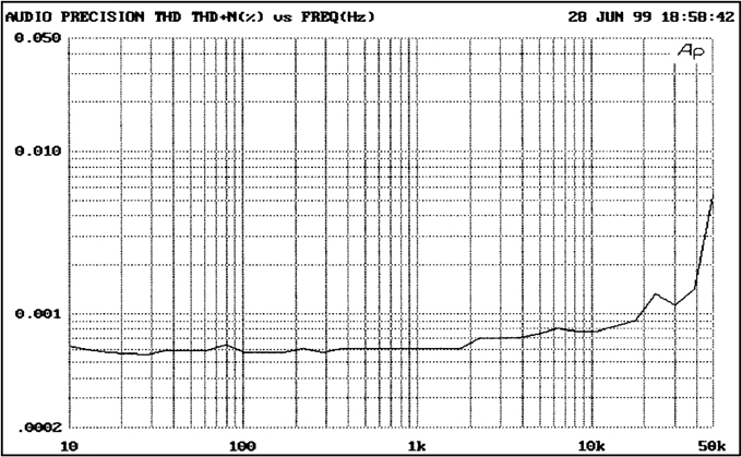
In some circumstances paralleled opamp stages are the simplest answer. This is sometimes called an opamp array or multi-path amplifier. There is much information on this in Chapters 1, 13, and 18, focusing mainly on the noise benefits; here I will concentrate on load-driving ability. In Figure 20.1 the upper trace shows a single 5532 section attempting to drive 5 Vrms into 220 Ω. The distortion is very high for a 5532, and it is clearly running out of current capability. Adding a second section in parallel with the outputs coupled by 10 Ω resistors, as shown in Figure 1.10 in Chapter 1, drops the THD back to the familiar low levels. The gains of the paralleled voltage-follower stages are very closely equal, so the small-series output resistors can allow for any microscopic differences, and no significant currents pass from opamp to opamp.

Figure 20.1 One and two 5532 sections attempting to drive 5 Vrms into 220 Ω.
This can be a very simple and cost-effective way to solve the problem of driving medium loads, and it can be extended by connecting more 5532 sections in a parallel, essentially without limit. Figure 20.2 shows four parallel 5532 sections driving 100 Ω to 5 Vrms with very little distortion. An array of 12 parallel 5532 sections can drive a 25 Ω load with 5 Vrms very effectively. Being me, I took the opamp-array technique to its logical conclusion, and possibly beyond, in my power amplifier for Elektor [3], which used 32 opamp packages, giving 64 parallel sections of 5532 joined with 1 Ω sharing resistors. This can easily drive an 8 Ω loudspeaker to 15 Wrms, with the usual very low 5532 distortion. The opamp supply rails limit the power output, so another version was designed that used two of these amplifiers bridged to give about 60 W/8Ω; the number of opamps in each amplifier was doubled to cope with the doubled load currents, so there were 128-off 5532 sections in parallel, each with a 1 Ω sharing resistor. This project was completely straightforward to design and test, and I think it demonstrates conclusively that you can use as many parallel opamps as you like.
Since the 5532 is usually the cheapest opamp available, using a number of them is not costly. The LM4562 will unquestionably give lower distortion but at the time of writing is significantly more expensive.
The best linearity is given by separating the gain and load-driving functions, as shown in Figure 20.5 further on. The first opamp provides all the voltage gain, so the output amps can be operated as voltage-followers with 100% negative feedback to give the best linearity.
As described in Chapter 1, paralleled opamps not only increase drive capability but also reduce noise and allow a lower effective output impedance when driving capacitive loads.
Opamp-Transistor Hybrid Amplifiers
When lower headphone impedances are to be driven, the number of multiple opamps required can become unwieldy, taking up an excessive amount of PCB area, and it becomes more economical to adopt a hybrid circuit. (These are “hybrid” circuits in that they combine IC opamps with discrete transistors; the name does not refer to thick-film construction or anything like that.) The usual procedure is to add a Class-AB output stage after the opamp. A Class-A output stage is perfectly feasible if ultimate quality is required, though the power consumption is naturally much higher and the efficiency with real signals something like 1%. The discrete devices could be either bipolar transistors or power FETs, but I invariably use bipolar transistors because their greater transconductance translates into better linearity, and they are totally predictable in every parameter that matters for this application.
I have always made it clear that Class-B and Class-AB in a power amplifier are not the same thing. Class-B is that unique quiescent condition where the distortion is a minimum. Class-AB is more highly biased so that it is effectively Class-A for small outputs, but above that, extra distortion is generated as the output devices switch on and off. Here the situation is very different, instead of the driver-output device pairs of a power amplifier, there is a single transistor that turns on and off more gradually. There is no real distinction between Class-B and AB and no need for critical biasing.
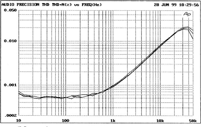
The arrangement in Figure 20.3a has been used for many years, dating back to when using a TL072 for the opamp made a significant cost saving. It is economical and dependable, and I have used it to drive headphones in low-cost mixing consoles. The output stage is the simplest possible version of Class-AB, but it really works quite well, though its distortion characteristics, as seen in Figure 20.4, are not of the highest standard. The output devices are TO92 small-signal types with high beta, and this is crucial to an acceptable distortion performance; the bias is set by D1, D2, and there is no adjustment. The gain is 3.2 times. Inserting extra stages into opamp feedback loops must be done with care to avoid adding extra phase shifts that may cause HF instability; here there are no problems, and no extra stabilising components are required. The output is AC coupled by C2 so that DC-offset protection is not required, and output resistor R7 takes care of short-circuit protection and caters for the different drive voltages required by 600 Ω and 30 Ω headphones.
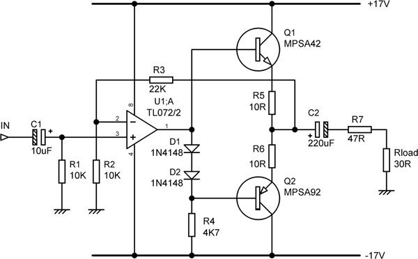
Figure 20.3 Traditional hybrid headphone amplifier combining a TL072 with a discrete Class-B output stage. Note the series output resistor R7, with typical value.
Figure 20.5shows a more sophisticated version with lower distortion and greater output into lower impedances. I have deployed it in preamplifiers with a headphone output. There are three TO92 output pairs giving greater drive power; no heat sinks are required. The gain is higher than in Figure 20.3 at 5.4 times (+14.6 dB) and is provided by A1, allowing A2 to work at unity closed-loop gain so there is maximal negative feedback for correcting errors in the output stage. Bootstrapping is applied to R6, R7 to maintain a relatively constant current through bias components D1, R5. C3 aids stability; at very high frequencies, the NFB is taken from before the output stage and does therefore not suffer phase shifts from it. This circuit is reliably HF stable with a 5532 for A2; an LM4562 in this position showed hints of instability, but this may be curable by adjusting C3. The noise output was measured at -107.0 dBu, so the EIN is -107.0–14.6 = -121.6 dBu, which is pleasingly low.
The distortion performance is shown in Figure 20.6, without use of a series output resistor. The 5 Vrms trace is higher due to the relatively higher noise level with a smaller output.
Discrete Class-AB Headphone Amplifiers
The hybrid circuit of Figure 20.5 is relatively complicated, and one starts to wonder if a wholly discrete solution might be more economical. Figure 20.7 shows a discrete headphone amplifier based on the discrete opamp designs of Chapter 3. The output stage is a simple complementary Class-AB configuration with fixed bias.


Figure 20.6 The hybrid headphone amplifier of Figure 20.5 driving a 60 Ω load. Upper trace 5 Vrms output, lower trace 9 Vrms output.
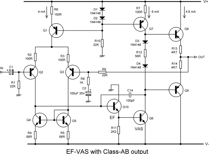
Figure 20.7 Discrete headphone amplifier with Class-AB output stage. Output devices are MJE340/350.
First we will look at the basic linearity with light loading. With a 3 kΩ load, the distortion residual at 1 kHz looks nothing like the characteristic crossover distortion seen in a power amplifier. It is pure third harmonic. This situation continues all the way up to 20 kHz, the residual remaining as pure third harmonic but increasing in relative level.
The distortion with light loading can be reduced dramatically by increasing the quiescent current in the output stage, by adding a biasing resistor R12 in series with the two diodes in the VAS collector circuit, as shown in Figure 20.7. The plot in Figure 20.8 demonstrates that HF distortion falls steadily as the value of the bias resistor increases, with no obvious sign of an optimal value. A 10 Ω resistor only gives a modest improvement, but 27 Ω reduces HF distortion by a factor of 5, and 56 Ω seems to give most of the improvement that is attainable. The latter corresponds to a quiescent current of 4.6 mA in the output devices. While in this form it makes a very useful model amplifier for studying the small-signal stages of power amplifiers, its distortion increases rapidly when heavier loads are driven.
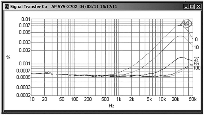
Figure 20.8 Effect of increasing output bias on discrete Class-AB amplifier with load of 3 kΩ. Added bias resistor R12 at 0R (top trace) 10R, 27R, 56R, 100R. +20 dBu output, ±20 V rails.

Figure 20.9 shows distortion remains low for a 220 Ω load but increases rapidly for heavier loading as the output stage is taken out of its Class-A region, and the THD residual becomes a complex mixture of higher harmonics, increasing at 6 dB/octave with frequency. When comparing this with other designs, be aware that the closed-loop gain is higher at 23 times.
Discrete Class-A Headphone Amplifiers
Because the power requirements of headphones are modest, it is quite practical to adopt an amplifier design that works in pure Class-A. This assumes that push-pull Class-A is used to get the maximum efficiency. Even so, with real music signals, the efficiency is likely to be as low as 1% at full volume and even less at lower levels.
Figure 20.10 shows another development of the discrete opamp using a Class-A output stage. The high quiescent dissipation means that TO-220 output transistors must be used; since these have relatively low beta, they are paired with TO-92 driver transistors, the result looking very like a full-scale power amplifier. The quiescent current is set at 90 mA by the bias generator Q9 and fixed resistors R12, R16, R17. No bias adjustment is required, as in Class-A the quiescent current is not critical.
In the prototype, a small vertical heat sink with a thermal resistance of 10 C/W (type SW38) was used for each output device, with the bias transistor Q9 mounted not just on the same heat sink but actually on top of output device Q12 for the best thermal coupling. The standard clip can still be used to hold the devices to the heat sink. From cold turn-on to full operating temperature, the quiescent remains within ±10%. A feedback control system could hold the quiescent current much more closely than this [4], but its complexity is hardly necessary at such modest powers. No short-circuit protection is required, because the output resistance R20, made up of two 33 Ω 750 mW resistors in series, can safely absorb the power if the output is shorted.
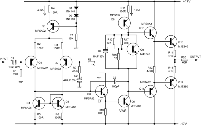
Figure 20.10 Class-A hybrid headphone amplifier with EF output stage.
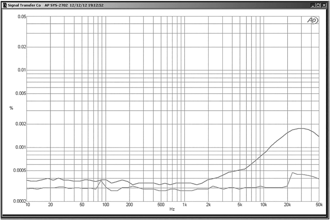
The distortion driving a 30 Ω load at 3 Vrms out is shown in Figure 20.11. The THD at 10 kHz is 0.0008%, comfortably below 0.001%, and predominantly second-harmonic. The maximum output is 3.3 Vrms due to the effect of the output resistor.
Because of the high performance of this relatively simple circuit, I think it is worthwhile to look at the measurements in more detail than usual:
| Gain | |||
|---|---|---|---|
| Measured gain | 5.52 times | +14.83 dB | No load |
| Measured gain | 4.97 times | +13.93 dB | (600 Ω load) |
| Measured gain | 1.74 times | +4.81 dB | (30 Ω load) |
| Maximum Output | |
|---|---|
| 10.5 Vrms | No load |
| 9.4 Vrms | 600 Ω load |
| 3.3 Vrms | 30 Ω load |
| Noise Performance | ||
| Noise measurements bandwidth 22–22 kHz, unweighted, RMS sensing, input terminated with 40 Ω | ||
| Noise out | -107.7 dBu | No output load |
| Equivalent Input Noise (EIN) | -122.5 dBu | |
| Noise out | -115.8 dBu | Output load 30Ω |
| Equivalent Input Noise (EIN) | -120.6 dBu | |
| Noise out is lower with the 30 Ω load because, with the series output resistor, it forms an attenuator. | ||
| Power Consumption | |
| 92 mA per amplifier from ±17 V rails | (3.2 watts) |
Balanced Headphone Amplifiers
It is believed by a small minority that a balanced drive to headphones can be of advantage. It is difficult to think of any technical reason why this might be so, because the moving-coil speaker elements are not connected to anything except the cables feeding them, so the presence of a common-mode voltage is irrelevant.
Most headphones will need to be rewired for balanced use, as the typical arrangement for high-quality headphones is to have a three-wire cable running from a ¼-inch jack plug to one earpiece, with a two-wire cable running from there to the other earpiece. This means that part of the ground connection is common to the left and right signals, and since it has some resistance it will cause interchannel crosstalk. Paradoxically, cheap headphones with a figure-of-eight cable that splits off to each earpiece may be better in this respect because there are separate grounds to each earpiece, and these only meet up at the jack plug, so there is the minimum amount of common ground resistance.
Four-way jack plugs do exist (with tip, two rings, and sleeve), but these are usually in the 3.5 mm size for mobile phone use. In hi-fi, the connection to headphones wired for balanced use is normally made with two three-pin XLR connectors.
References
[1] Self, Douglas “Preamplifier 2012” Elektor, Apr/May/Jun 2012
[2] Self, Douglas Audio Power Amplifier Design 6th edition. Focal Press, 2013, p 107
[3] Self, Douglas “The 5532 Op Amplifier” Elektor, Oct/Nov 2010
[4] Self, Douglas Audio Power Amplifier Design 6th edition. Focal Press, 2013, pp 429–432