Chapter 3: Building an Industrial Robot Claw
Industrial robots have been around for a long time. In many cases, industrial robots are not the humanoid-looking robots we imagine when thinking of robots. Instead, many are robot claws that can do a wide variety of tasks: surgery, welding, assembly, painting, and more. In this chapter, you are going to build a robotic claw pick up a red ball that comes with the kit, to better understand how these claws work and operate. In the following screenshot, you can see what you will be building:

Figure 3.1 – Robotic claw
In this chapter, we will break down the build and program, as follows:
- Build the frame for the Intelligent Hub
- Setting up the motor frame to move right and left
- Setting up the motor frame to move up and down
- Framing the motor that operates the claw
- Writing the code
Technical requirements
For the building of the robot, all you will need is the Robot Inventor Kit. For programming, you will need the LEGO MINDSTORMS app/software.
Access to the code can be found here: https://github.com/PacktPublishing/Smart-Robotics-with-LEGO-MINDSTORMS-Robot-Inventor/blob/main/Chapter%203%20Claw%20Code.lms.
If you would like a more detailed photo-by-photo build process of the robot, please head here: https://bit.ly/2NkkypN
Building the claw
Before we build the claw, let's explore the strategy being used for these claws. There are many LEGO robotic claws to be found online. This one tries to do some things differently, as follows:
- The claw needs to be able to be controlled by a human.
- The claw needs to be able to move from side to side.
- The claw needs to be able to move up and down.
- The claw needs to be able to open and close the claw to grab various objects.
We are going to start this build using a large teal 11x19 base plate as the main building foundation for this robotic claw. Ensuring that we have a solid foundation is key, and the teal 11x19 base plate shown in the following screenshot is perfect for building on top of when designing an claw:
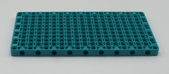
Figure 3.2 – The LEGO teal base plate
Let's build the robotic claw now, starting with the frame for the Intelligent Hub!
Building the frame for the Intelligent Hub
One part of this kit that is different from previous Mindstorms kits is that the wires for all sensors and motors are set to a specific length. In previous kits, we could attach various cable sizes as we built our bigger structures.
Because all wires are a set length that we cannot adjust, we must consider this creative constraint in the build design. With that being said, we need to build a frame to place the Intelligent Hub at a certain height to allow the motors to be able to reach the Intelligent Hub while in motion.
You will need the following pieces:
- Two black 11x15 open frames
- One black 7x11 open frame
- Four gray connector pins with bush stops
- Four black connector pins
The required pieces are shown in the following image:

Figure 3.3 – Overview of parts needed to begin the build
Start by adding the two black 11x15 open frames to the side of the teal base plate. Use the gray connector pins to hold them in place by inserting them through the pinholes into the sides of the teal base plate.
Using two black connector pins on each side, secure the black 7x11 plate to the top of the black 11x15 open frames, as illustrated in the following image:
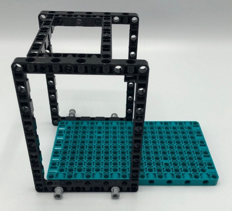
Figure 3.4 – Building a stand for the Intelligent Hub using the open frames
Using two large open frames and one medium-sized open frame, we will assemble a standing desk for the Intelligent Hub. We will attach the Intelligent Hub to the top, where it will sit one row off the back of the base plate. The final step of this part of the build is to add the Intelligent Hub to the top of the frame.
Setting up the motor frame to move right and left
This section sets the foundation to the entire robotic claw. You will start by building a strong base for the claw to establish the motor that will allow the claw to move right and left.
You will need the following pieces:
- Intelligent Hub
- One motor
- Six black connector pins
- Two gray perpendicular connector pins, bent
Start by adding four black connector pins to the four corners of the bottom side of the Intelligent Hub, as illustrated in the following image:
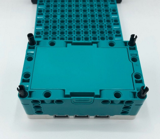
Figure 3.5 – Pin placement on the underside of the Intelligent Hub
Go ahead and connect the Intelligent Hub to the top of the base you just assembled. It should lock into the 7x11 open frame, as illustrated in the following image:
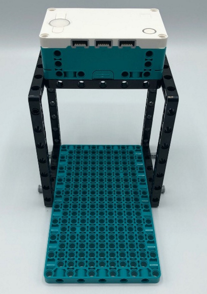
Figure 3.6 – Stand for the Intelligent Hub
Using one motor, two gray perpendicular connectors, and two pins, we can secure the motor to the base, as illustrated in the following image:

Figure 3.7 – Parts needed to secure motor to base
Make sure your motor is properly secured to the base. To do this, add the gray connector pins to the sides of the motor, along with the black connector pins in the middle pinhole of the motor on both ends, as illustrated in the following image:
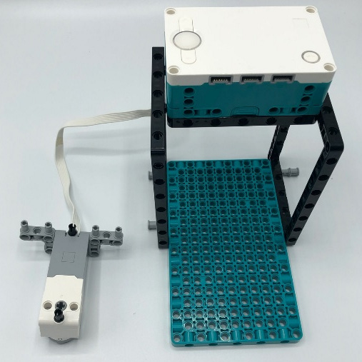
Figure 3.8 – Gray connector pins attached to the motor
When you connect the motor, we will place it three rows back from the front of the base plate. Place the black pins on the underside of the motor to really secure it to the base, as illustrated in the following image:
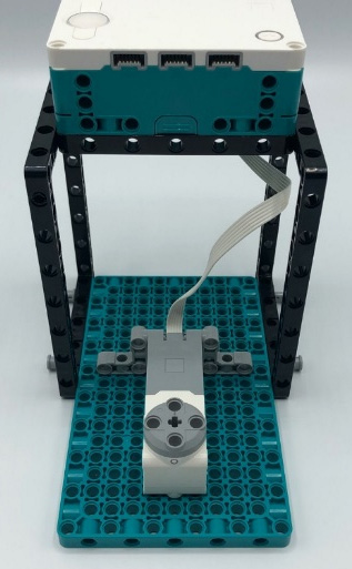
Figure 3.9 – Placement of the motor
Next, it is time to build a solid frame for the motor and turntable, for the claw to properly move. You will craft a table using the following pieces:
- One turntable
- Four blue connector pins
- One teal 3x3 Technic piece
The required pieces are shown in the following image:
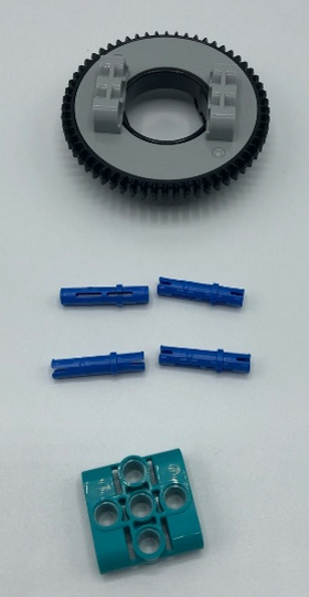
Figure 3.10 – View of the unassembled turntable
To begin this part of the build process, start by sliding the 3x3 teal Technic piece in the middle of the turntable, on the gray side. Ensure the pinholes align with the gray pinholes of the turntable. Secure the teal 3x3 piece to the turntable using two blue connector pins on either side, as illustrated in the following image:

Figure 3.11 – View of turntable piece assembled
Locate the following parts to go along with this turntable piece:
- Two black 11L beams
- Two gray connector perpendicular pins
- Two teal 3x3 Technic pieces
- One teal 3L beam
- Four blue connector pins
The next screenshot provides a basic layout on how to attach all these pieces together, with a step-by-step description to follow:
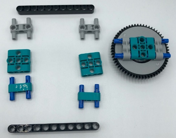
Figure 3.12 – General layout of parts
The following steps align with the preceding image, starting from the top and working down:
- Start with one black 11L beam.
- Add the two gray perpendicular pins to the outside edges.
- Next, attach a 3x3 teal Technic piece to each of the gray pins.
- Follow this up by adding two blue connector pins to the outside holes of the teal 3L beams and connect these to the 3x3 teal pieces.
- Before you finish this build, insert the turntable piece right into the middle of this part, as shown in Figure 3.13, using the blue connector pins exposed on the turntable.
- Finally, secure it all together with the second black 11L beam.
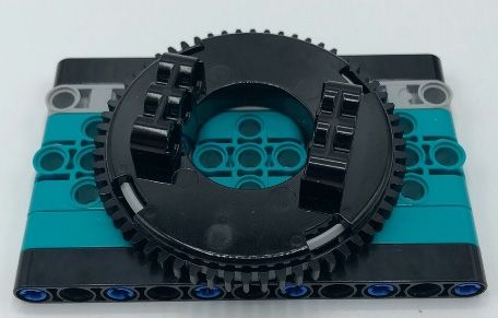
Figure 3.13 – Turntable fits in middle
This is what it should look like on the underside, to ensure you have things properly placed. The turntable should spin freely:

Figure 3.14 – Black connector pins in the second pinhole from the edges
If all is good, then find four black connector pins and add them to the black beams in the pinholes one hole from the end
Now that this piece is assembled, we will attach this to another open frame.
You will need the following pieces:
- Two teal 2x4 L beams
- Two black 2x4 L beams
- One 7x11 black open frame
- Four black connector pins
Add two black connector pins on both 11L sides of the open frame, as illustrated in the following image:

Figure 3.15 – Black pins added to the open frame
Next, you will stack the turntable piece on top of this open frame, as illustrated in the following image:

Figure 3.16 – Stacking the turntable piece on the open frame
After these two build pieces are stacked, then go ahead and use the 2x4 L beams and connect the turntable piece to the open frame, as illustrated in the following image:
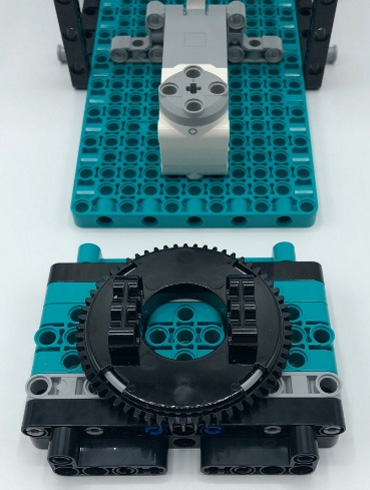
Figure 3.17 – View of the built turntable piece
Go ahead and find the following pieces:
- One yellow 5L axle
- One white connector piece
- Two black 5x7 open frames
- Four black connector pins
- Four gray connector pins with bush stops
The required pieces are shown in the following image:
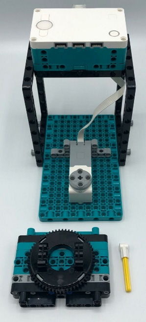
Figure 3.18 – Yellow axle to begin to connect parts
Insert the white connector piece to the end of one side of the yellow axle. Insert the yellow axle through the middle of the turntable, securing it to the middle pinhole of the motor that is placed on the main teal base plate, as illustrated in the following image:
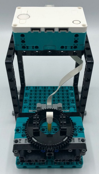
Figure 3.19 – The turntable will sit low
The following image shows the elements you should now have left:
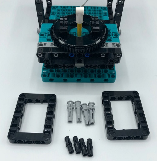
Figure 3.20 – Parts needed for this build section
Using your 5x7 open frames, gray connector pins, and black connector pins, you are going to add these parts to the sides of the turntable piece to secure and mount it to the main base plate, as illustrated in the following image:
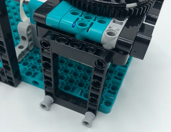
Figure 3.21 – Gray connector pins hold frames to base
The next step is to lock the motor to the turntable to allow the entire claw to move right and left. These parts will connect the top of the claw to the turntable.
You will need the following pieces:
- Four teal T Technic pieces
- Four blue connector pins
- Four black connector pins
- Two black 7L beams
- One black 12L axle
- Two gray axle bushes
To build these parts you will connect the T pieces to each of the black 7L beams, using two blue connector pins. Both parts will be built with the T piece being on the outside of the black beam. You will build two of these parts with the T teal piece on the outside, as illustrated in the following image:

Figure 3.22 – T teal piece on the outside of the beams
You will then add each of these parts to either side of the turntable, locking them into place. This is illustrated in the following image:

Figure 3.23 – Side view of build model
Find the 12L axle and two gray bushings. These are illustrated in the following image:
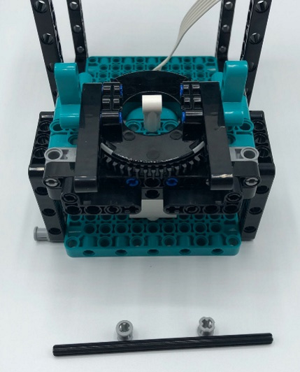
Figure 3.24 – Parts to secure all elements together
Slide the 12L axle through the middle pinhole of the T pieces and through the white pin connector in the middle of the turntable. Secure the axle using the two gray bush stops on the ends of the axle, as illustrated in the following image:
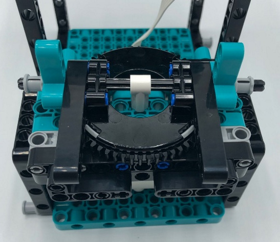
Figure 3.25 – Holding together with gray bush stops
The final step in this build part is to now attach the final two teal T Technic pieces to the end of the black beams that are now on the turntable. Use two black connector pins on each one to attach, as illustrated in the following image:
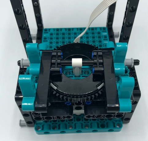
Figure 3.26 – View of build at this current step
Your next step in this build is to build up the frame for the other motors, for the claw to be built upon.
To get started, you will need the following pieces:
- Four white panels
- Four blue axle pins
- Twelve black connector pins
- Four teal 3x5 L beams
- Four black 3x5 beams
To begin, locate two white panels, and on each of them add two black connector pins, as illustrated in the following image:
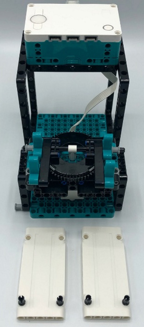
Figure 3.27 – White panels for the claw
Using the black connector pins, attach the white panels to the teal T parts that are currently on the turntable, as illustrated in the following image:
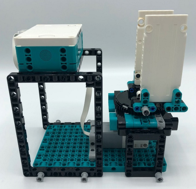
Figure 3.28 – Two white panels added to the turntable
This is how the build will look from the side now:
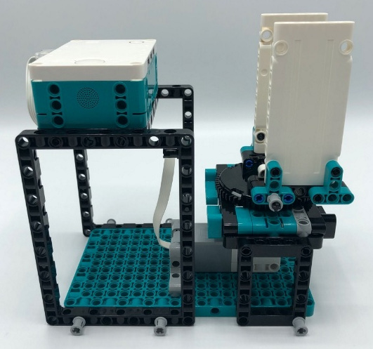
Figure 3.29 – Side view of the build
With the build facing you, where the turntable is to the front and the Intelligent Hub is to the back, add a black connector pin and a blue axle connector pin to both white panels, as illustrated in the following image:

Figure 3.30 – Placement of connector pins
The last step to complete on this part of the build is to add two more panels, to complete the main structure of the claw. Note the parts to secure the two panels, using the L-shaped Technic pieces in the following image. One white panel will use the four teal 3x5 L beams, and the other will use the four black 3x5 L beams.
This is how it would look from the front after adding the panels:

Figure 3.31 – Third white panel added
This is how it would look from the other side of the panel:

Figure 3.32 – Fourth white panel added
Here is how the build should look at this point in time:
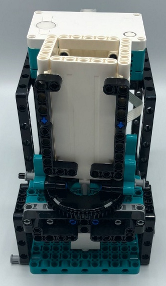
Figure 3.33 – Top view of the white panels
Let's finish up this part with the final pieces. You will need the following pieces:
- Twelve black connector pins
- Three black 5x7 open frames
- Two blue connector pins
Begin by adding four black connector pins to the corners of the white panels on the top of the build, as illustrated in the following image:

Figure 3.34 – Adding black connector pins to the panels
Using the two blue connector pins, insert them in two corners of one of the open frames, as illustrated in the following image:
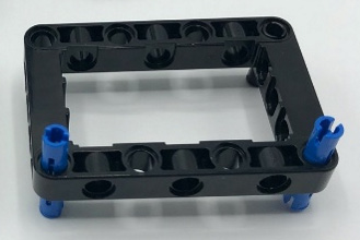
Figure 3.35 – Parts for the base of the claw motor
Stack the three open frames together, using six of the black connector pins. Placement is not essential, but you just want to make sure they are securely held together. The last two black connector pins will be added to the top, between the two blue connector pins, as illustrated in the following image:
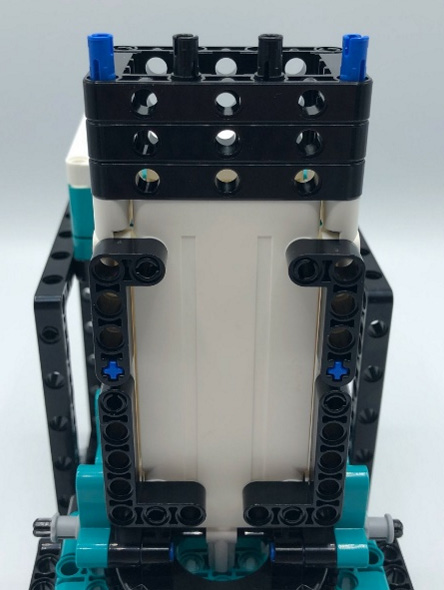
Figure 3.36 – Open frame stand for claw
Now that we have set up the motor frame to move left and right, let's see how to set it up to move up and down.
Setting up the motor frame to move up and down
You are now ready to add the two motors that will control the claw's upward and downward movements.
You will need the following parts:
- Two motors
- One gray 3L axle
- Two teal 5L beams
- Six black connector pins
- One teal 3x3 Technic piece
Grab two motors and connect them with a 3L axle, as illustrated in the following image:
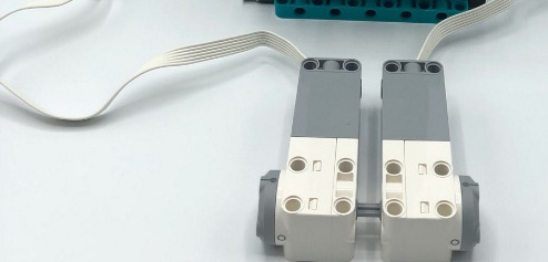
Figure 3.37 – Connected motors using 3L axle
Add them on top of the four connector pins, on top of the three open frames, as illustrated in the following image:
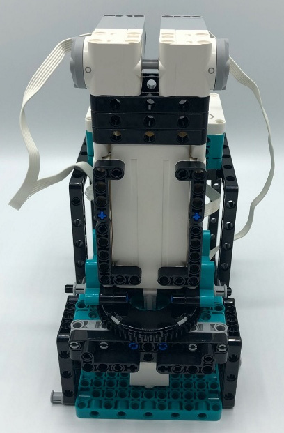
Figure 3.38 – Placement of motors on top of open frames
Using the two teal 5L beams and four of the black connector pins, secure the motors together, as illustrated in the following image:
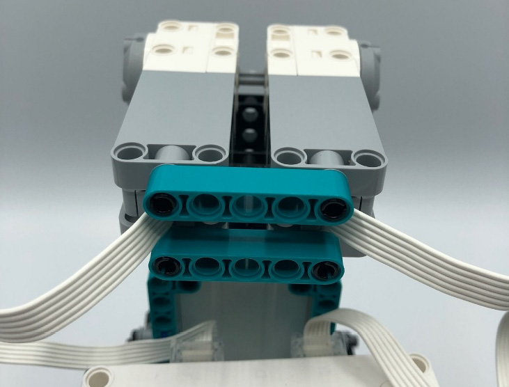
Figure 3.39 – Securing the motors together
At this point, you need to fold up and hide the wires. We will close off the wire and secure these 1x5 beams using one 3x3 teal Technic piece and two black connector pins, as illustrated in the following image:
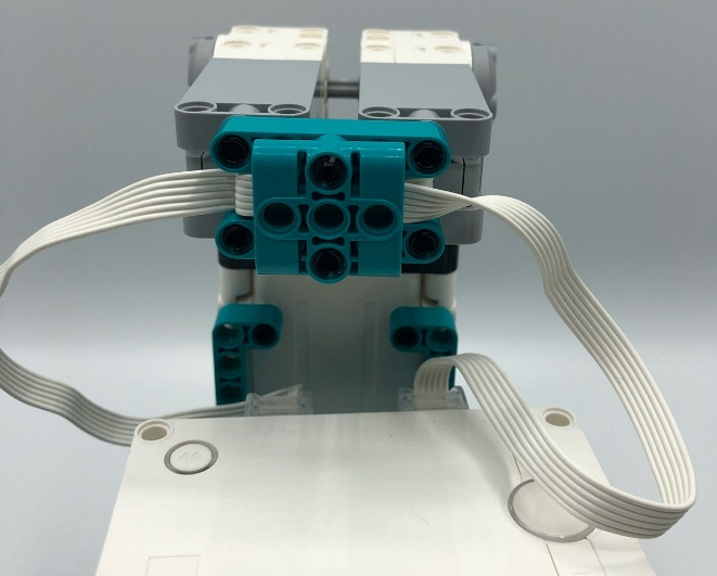
Figure 3.40 – Securing the motor wires
You can now plug these motors into ports B and F. If you have not already done so, you can also add the motor at the bottom of the base to port C. After you have connected the motors, let's keep building from the motors. Next, you will need to add a gray 3L axle to the middle of each of these motors. After that, add a gray perpendicular connector pin to each motor. The result is shown in the following image:
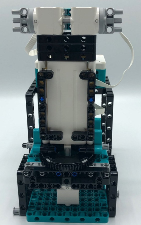
Figure 3.41 – Robot claw main frame
This would be a great time before you continue building to run a test code, to ensure your claw can move from right to left and to tweak any adjustments that need to be made. Write a simple program moving the motor just to make sure it moves.
Framing the motor that operates the claw
You are now down to your final motor that will control the claw being able to open and close.
For this section of the build, you will need the following parts:
- One motor
- One gray 3L axle
- Two black connector pins
- One teal 5L beam
Start this build part by adding two black connector pins and the gray 3L axle to the pin holes on the motor, as illustrated in the following image:

Figure 3.42 – Preparation for claw motor
Attach the teal 5L beam to the connector pins that you just added to the motor in the previous step, as illustrated in the following image:

Figure 3.43 – Adding the 5L beam to the motor
You are going to continue to build out the claw on this motor. To do so, you will need the following parts:
- Two black connector pins
- Two black 45-degree beams
- One gray 3L axle
- One black axle and pin connector
Start by adding the two black connector pins to the ends of the 5L beam, as illustrated in the following image:

Figure 3.44 – Parts for first phase of claw
Using the first pinhole of the black 45-degree beams, add one pin to each end. On the 45-degree beam that is on your right side, insert the 3L axle in the second pinhole and secure it using the black pin and axle connector piece, as illustrated in the following image:

Figure 3.45 – Base of the claw
Now, locate the following parts:
- One black 2L pin axle connector
- Two tan axle pin connectors
- One gray 3x5 perpendicular H-Shape beam
You will connect the axle and pin connector to the motor using a 1x2 beam, as illustrated in the following mage:

Figure 3.46 – Top view of the base of the claw
Take the second tan axle pin connector and add it to the other 45-degree beam using the axle hole, as illustrated in the following image:
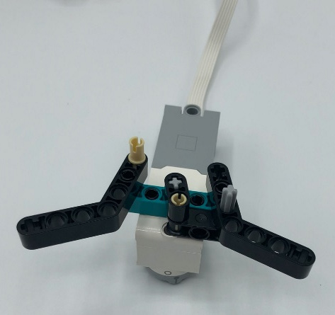
Figure 3.47 – Connector placement for movement
Additionally, you will hold everything in place while allowing movement of the claws by layering on the H-Shape Technic element. Again, check the placement of the connector pins to allow the claw to move properly. The result should look like this:

Figure 3.48 – H shaped piece to help with claw movement
Let's get this claw all put together. You will need these pieces next:
- Four black 45-degree beams
- Two blue pin axle connectors
- Two brown 3L axles with end stops
The required pieces are shown in the following image:

Figure 3.49 – Parts for second phase of claw build
Insert a brown 3L axle through the end of each of the 45-degree beams in the axle hole. Be sure the 45-degree beams are bent to face inward as these are part of your claw mechanism.
Insert a blue axle pin connector into the end of the 45-degree beams that are already attached to the motors.
Connect the 45-degree beams that have the brown 3L axle to the 45-degree beams that are attached to the motors. You will start to see the formation of a claw. The next image provides a visual of what your build will look like after this series of steps:
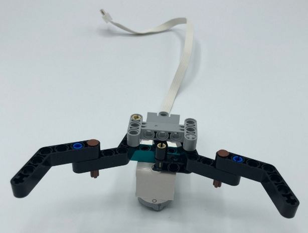
Figure 3.50 – Connecting 45-degree beams together
Find two more 45-degree black beams and attach them to the underside, where the brown 3L axle is still showing. Connect by using the axle hole of the 45-degree beams, as illustrated in the following image:

Figure 3.51 – Second-phase build of claw view
Let's keep building this claw to ensure it can grip the red ball that comes with the kit. You will need the following pieces:
- Two black 45-degree beams
- One black connector pin
- One blue axle pin connector
- One black 3L beam
- One dark-gray axle pin connector
- One blue connector pin
- Two yellow 5L axles
- Four black rubber 1x2 axle connectors
To start this part of the claw, begin by attaching a 45-degree beam to the right side of the claw. Use the black connector pin and the blue axle pin connector to secure it into place. Note how the beam will stick out from the inside. The black connector pin is inserted in the pinhole to the right of the brown axle. The blue connector pin is used to the right of the black connector pin, as illustrated in the following image:
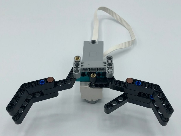
Figure 3.52 – Adding support bracket for an object on the right claw
Let's move to the left side of the claw. For this side, you will need the following parts:
- One 45-degree black beam
- One 3L black beam
- One dark-gray pin axle connector
- One blue connector pin
The required parts are shown in the following image:

Figure 3.53 – Parts for support bracket for object on left claw
Start by attaching the 3L beam to the 45-degree beam. Use the dark-gray connector pin on the end of the 45-degree beam using the axle hole. Add the 1L side of the blue connector pin to the pinhole next to the axle hole, as illustrated in the following image:
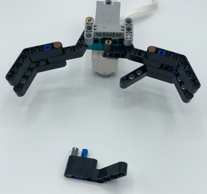
Figure 3.54 – Assembled parts for support bracket for an object on left claw
This part will connect to the underside of the left side of the claw, as illustrated in the following image:

Figure 3.55 – Assembled view of support brackets on the left claw
Secure all the parts of the claw together using the yellow 5L axle pieces. Insert each axle onto the end of the claw, as illustrated in the following image:
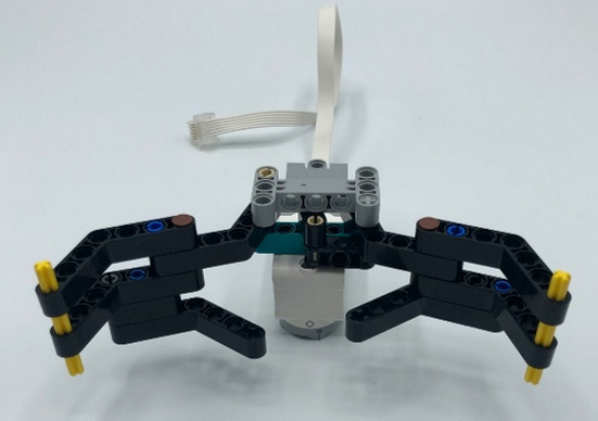
Figure 3.56 – Yellow axles added to the claw
The last part to this claw is to attach the two black rubber axle parts to the ends. These parts help with gripping the red ball upon pickup and are shown in the following image:

Figure 3.57 – Grippers to hold the ball
When the robot claw rises to its full extent and brings the ball straight up, the claw cannot contain the red ball without the rubber attachments. Using the rubber elements and an extra holding mechanism that does not get in the way of the claw moving, we can finish up the claw to better stabilize the red ball while in motion. Note that you can adjust and modify the claw to your own needs if you want to grab other items besides the red ball.
Keep in mind that you can create the claw to your liking at this point in time. This claw was designed to pick up and move the red ball in the kit. You might need to adjust the claw if you wanted to grab different items or objects.
The final step of the claw is to attach this claw mechanism to the rest of the robot body. You will need the following parts:
- Two white 13L beams
- Two teal 5L beams
- Two black 5L beams
- Two black 3L beams
- Two black 9L bent beams
- Six blue connector pins
- Four black connector pins
- Two dark-gray pin axle connectors
In the following image, you will see what the build looks like on the right side, with the elements needed on the left side:

Figure 3.58 – Claw support beams to add to the main frame
You will build two of these parts so that you have one for each side of the claw motor, to be attached to the main base of the robot.
Start with the white 13L beam. Insert two blue connector pins in pinholes 3 and 7, as illustrated in the following image:

Figure 3.59 – Blue pin connectors added to white beam for brackets
Attach the teal and black 5L beams to the blue connector pins. Add two black connector pins to the black beam, as illustrated in the following image:
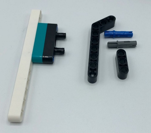
Figure 3.60 – Adding the 5L beams
Next, add the bent 9L beam, with the bent piece facing up. Add the dark-gray connector pin into the axle hole of the bent beam and the blue connector pin to the base of the bent part of the beam. Finally, slide the black 3L beam over these pins, as illustrated in the following image:

Figure 3.61 – Assembled view of the bracket
Repeat this process for the second piece, and just be sure that both pieces have the white beam on the outside of the build, as illustrated in the following image:
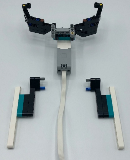
Figure 3.62 – Layout of the brackets for the claw
Once you have checked to make sure they are built properly, then go ahead and connect to the claw on the back of the motor. Just to double-check, you should have the following two parts built at this point in time, as seen in the next image:

Figure 3.63 – Two build components you should have at this point
The final step of this build is to add the claw attachment to the main frame. Connect the claw to the motors at the top of the robot claw on the base. You can adjust the claw on the 1x13 Technic beam, but I have found this setup to be most effective when the motor is not slipping and is moving properly. The result is shown in the following image:

Figure 3.64 – The claw attachment set on the robot
A key detail here is the wire of the claw motor. It needs to be run between the two B and F motors to reach the Intelligent Hub properly, to allow for proper movement. You will connect the claw motor to port D. Check your wires by moving the claw to the right and left, checking for snags with the wire.
Here is what the robotic claw should look like from the left when completely assembled:
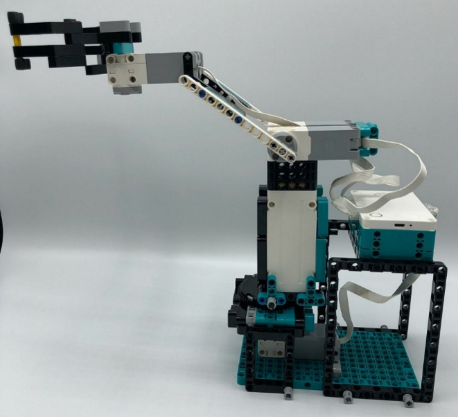
Figure 3.65 – Left-side view of the completed robotic claw
This is how it should look from the front:
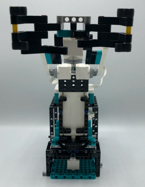
Figure 3.66 – Front view of the completed robotic claw
This is how it should look from behind:
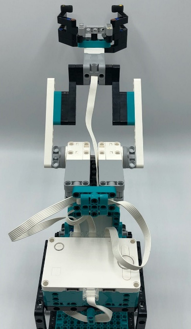
Figure 3.67 – Rear view of the completed robotic claw
And this is how it should look from the right:
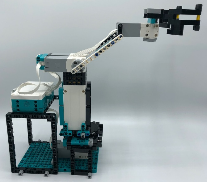
Figure 3.68 – Right-side view of the completed robotic claw
Now that your claw is complete, it is time to move into the coding to bring the robot claw into use.
Writing the code
For this build, we are going to focus on the remote app coding only. This will be a program that will allow you to control the robot using the remote-control feature of the app to move the claw right, left, up, and down, and to open and close the claw.
Overall, this program is fairly simple to develop and is created to be easily adaptable for you to remix to meet your needs. Use this sample code to make sure everything works, and then begin to tweak the code to make it work to your needs. Make sure you have the proper ports plugged in, and then move into the code.
Identifying the ports
If you have not plugged in your motors yet, then let's get them plugged in to the proper ports. You will plug the motor that moves the claw to the right and left to motor port C. The motor that controls the opening and closing of the claw will plug into port D. The two motors that control the arm of the claw to go up and down will use ports B and F. Once you have the motors plugged in, then double-check that the motors are plugged in correctly.
You can check that your motors are properly plugged in by checking the Port View in the software, as seen in the following screenshot:
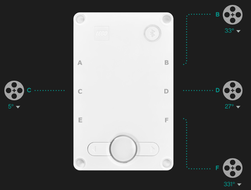
Figure 3.69 – Port View in the MINDSTORMS software
It is time to write the program so that you can control the claw.
Remote-control robot program
To get started with this program, let's go ahead with the following steps to make the robot come to life:
- Open up the MINDSTORMS software.
- Click on Projects at the bottom of the menu bar.
- Scroll down to Other, click or press the icon, and then select Create New Project.
- On the New Project window, select the Word Blocks option, and click on Create.
- Before we can activate the Remote Controller blocks, we have to turn on the commands we need. In order to do this, we must click on the joystick icon on the right-hand side of the screen, as illustrated in the following screenshot:

Figure 3.70 – Joystick icon on the right-hand side of the screen will pull up the control panel
- This will give you the screen needed to build your remote control. Once you are here you need to select the edit icon, which is the pencil in the upper right-hand corner, as shown in the following screenshot:

Figure 3.71 – Choose the pencil icon to create your controller
- On this Remote Control window, select the teal plus icon at the bottom of the screen to add the necessary widgets. In this project, we will select two of them. We will add the D-Pad and the Horizontal Slider widgets. Feel free to use a different widget configuration to control your robot, but for the sake of this example, we will use these two widgets. The different widgets available are shown in the following screenshot:
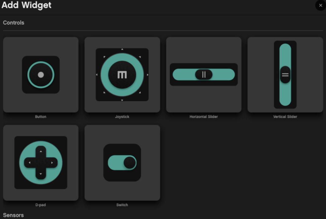
Figure 3.72 – Choose the Joystick and Button widgets
This is what you will need for your controller layout:
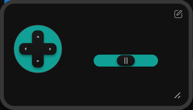
Figure 3.73 – Controller layout
Be sure to select the teal check to save your design, as shown in the bottom-right corner of the following screenshot:
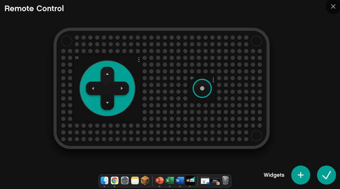
Figure 3.74 – Teal check in bottom-right corner to save settings
You can also move widgets around the grid to place them where you would like for your remote controller. Each person has preferences, so adjust to your needs. Figure 3.73 shows the controller layout I prefer to give an example of what the controls can look like on the remote control.
- Let's start with what will happen when the program starts. As mentioned earlier, the code is simple and is open for you to make it unique. Essentially, what we want to do here is make sure that the robot is aligned and ready for use. Using the blue motor block section add two blocks, adjusting the speed of motors C and D to a low speed to align to position 0. This will move the robot to a starting position of facing forward, ready to get to work. The speed is low so that it does not go crazy, and this keeps the movement smooth. The startup code is illustrated in the following screenshot:

Figure 3.75 – The basic startup code
- The next step is to get the robot to move up, down, right, and left. I have organized the coding blocks to mimic the directional pad. Again, the speed of the motors is low, at around 5%, to keep movement slow and steady. The code is pretty straightforward, using the blue motor blocks and pink movement blocks. Please note, as seen in the following screenshot, that you are using some pink movement blocks that are part of the extension section of the code. Please activate the More Motor and More Movement blocks to find the blocks used in this program:
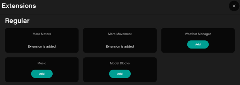
Figure 3.76 – Extensions block menu
Test your code and make sure the claw moves to your liking. You might need to tweak the numbers a bit to make it work the way you want. I prefer a code layout that mimics the controls, as you can see in the following screenshot:

Figure 3.77 – The code
- The final step is programming the claw to open and close. Using the teal remote-control blocks to activate the horizontal slider, we will add some simple code to have the motor open and close to our liking.
The speed is low, and we can duplicate the code and change the direction of the motor when the slider is high compared to low. The code blocks in the following screenshot showcase the low speed of 5% to move the claw:
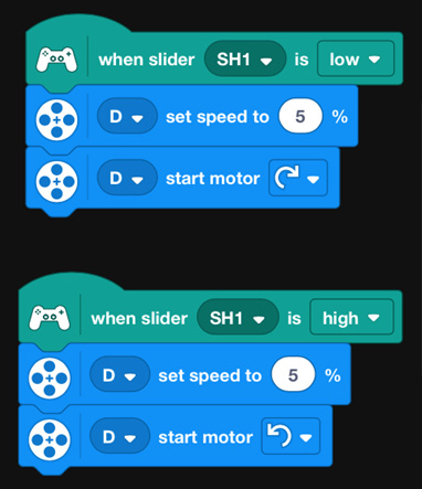
Figure 3.78 – Claw code
In the end, your code will look something like this:

Figure 3.79 – Final display of code
And that is it! You did it. You built a nice-looking and working robot claw. Now comes the fun part, which is to remix the claw to make it your own. Let's look at some ideas.
Making it your own
This is the part I love, and I hope you do too. This robot is just the beginning of the fun. It is now time for you to take this framework of the robot build and sample code, to make it unique to your talents and imagination.
Here are a couple of ideas to consider applying to this robot:
- Add sensors to trigger autonomous robot decisions. For example, could you add a color sensor so that as the claw moves, it is waiting to detect red to stop and pick up the ball and move to another location?
- Add lights of the light-emitting diode (LED) matrix on the Intelligent Hub to provide insights or cool new looks as the robot operates.
- Add sound effects to make it sound like an industrial robot.
Summary
In summary, we explored the concept of industrial robots by building a robotic claw that can pick up a red ball and transport it to another location. Industry continues to rely on robotics to achieve production goals. Additionally, we explored how to have several motors working together to create an actual working claw. This is a classic build that must be done with any new robotic kit!
Let's now head to the next chapter and explore a whole different world of robotics by building a guitar!