2
UML: A QUICK REFERENCE
UML offers 12 diagrams towards representing an application’s requirements analysis and solution design. Each of these 12 diagrams can be classified into 3 categories as follows.
STRUCTURE DIAGRAMS
UML offers the following four structure diagrams, which can be used to represent the static structure of an application.
- Class diagrams
- Object diagrams
- Component diagrams
- Deployment diagrams
BEHAVIOR DIAGRAMS
UML offers the following five behavior diagrams, which can be used to represent the dynamic behavioral aspects of an application.
- Use Case diagrams
- Sequence diagrams
- Activity diagrams
- Collaboration diagrams
- Statechart diagram
MODEL MANAGEMENT DIAGRAMS
UML offers the following three model management diagrams, which can be used to represent how different application modules are organized and managed.
- Packages
- Subsystems
- Models
Class and sequence diagrams have been provided for examples in this book. This section provides a brief introduction to the class and sequence diagrams and explains the different class/sequence diagram elements used in this book.
CLASS DIAGRAMS
Class diagrams are part of the structure diagrams and are used to describe the static structure of a system. The structure and behavior of classes and their association with other classes are depicted inside of a class diagram.
Class
Figure 2.1 shows the generic representation of a class.
It consists of three compartments (rectangular sections). The class name is placed in the topmost compartment. The set of attributes (both instance variables and class variables) are listed in the second compartment beneath the class name compartment. The set of methods/operations is listed in the third compartment.
Though the generic representation consists of three compartments as described above, the compartments may vary in number and type. One can suppr ess compartments and also have additional compartments to accommodate such aspects as constraints and tagged values.
Figure 2.2 shows an example of a class.
| ClassName |
| Attributes |
| Operations |
Figure 2.1 Generic Class Representation
| Customer |
| -name:String |
| -userID:String |
| -password:String |
| +getName(J:String |
| +setName(newName: String) |
| +getUserID():String |
| +setUserID(newUserID:Str:Ing) |
| +getPassword():String |
| +setPassword (newPassword:String) |
Figure 2.2 An Example Class Representation
Inner Class
An inner class is a class defined inside another class. The concept of an inner class exists in some of the object-oriented languages such as Java, C++ (through struct and enum) and C# (with true inner classes), but is not a standard object-oriented concept.
UML does not provide a definite way of representing an inner class. The notation shown in Figure 2.3 is used in this book to represent an inner class, where the inner class is placed in the operations section of class in which the inner class is defined.
Figure 2.4 shows an example of an inner class Memento defined inside the DataConverter class.

Figure 2.3 Inner Class Representation

Figure 2.4 An Example Inner Class Representation
Access Specifiers
In Java, the visibility of different members of an object and their accessibility by different client objects is controlled using access specifiers. Access specifiers for attributes and operations can be specified using symbols from Table 2.1.
Table 2.2 lists Java access specifiers and their scope.
In Figure 2.2 (Customer class) name is a private attribute and getName is a public method.
Static
Underlining a variable or method of a class specifies it as static (with class level scope). In Figure 2.5, the method getInstance is a static method of the FileLogger class. Client objects can invoke the getInstance method on the FileLogger class without having to create its instances.
Table 2.1 Access Specifiers Symbols
Table 2.2 Access Specifiers: Scope Details

Figure 2.5 Static Method Representation
Abstract Class/Method
A method without body, in a class, is referred to as an abstract method. A class with at least one abstract method is treated as an abstract class. Client objects may not instantiate an abstract class. A subclass of an abstract class must implement all abstract methods of the abstract class or be declared as an abstract class itself.
Displaying a class/method name in italics specifies it as an abstract class/ method. The Creator class in Figure 2.6 is an abstract class with an abstract method factoryMethod.
Exception
A dashed arrow with a stereotype label “throws” is used to indicate that a specific method throws an exception. The arrow points from the method to the exception class. Both the methods isValid and save in Figure 2.7 declare to (possibly) throw an exception of the java.rmi.RemoteException type.
Note
A note is attached to a UML diagram to provide additional information for a symbol such as comments, constraints or code. In general, notes can be attached to any diagram element in any UML diagram.
A note is denoted by a dog-eared rectangle and is attached to a diagram element by a dotted line. Figure 2.8 shows a note attached to the attribute of a class.
Generalization
Generalization is used to depict the object-oriented concept of inheritance when there is a base class with common behavior and each of its derived classes contains specific details/behavior.

Figure 2.6 Abstract Class/Method Representation

Figure 2.7 Representation of Methods Throwing Exceptions

Figure 2.8 A Note to Provide Additional Information
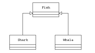
Figure 2.9 Inheritance Relationship
In Figure 2.9, the closed, hollow arrowhead pointing from the Shark/Whale subclass to the Fish superclass represents generalization.
Interface
An interface specifies the externally visible operations of a class, but not the actual implementation of those operations. An interface often specifies only a part of the behavior of an actual implementer class. An interface can be drawn using a class-like rectangular setup, with the text “interface” above the name of the interface. Figure 2.10 shows an interface named VisitorInterface.

Figure 2.10 An Interface
Realization
A realization depicts the relationship between an interface and a class that provides the actual implementation. This can be drawn in two ways depending on how the interface is depicted.
- Using a closed, hollow arrowhead pointing from the implementing class to the interface with a dashed line
- With a line and a circle, where the circle represents the interface (with the name of the interface kept near the circle) and the line can be drawn pointing to the class that implements the interface represented by the circle.
In both Figure 2.11 and Figure 2.12, the OrderVisitor class implements the interface declared by the VisitorInterface (Java) interface.
Dependency
A dependency depicts the relationship between a source and a target component, when there is a dependency relationship between the two. It means, when there is a change in the target, the source element undergoes a necessary change but not vice versa.
The Order class in Figure 2.13 makes use of the execute method of the DBUtil class to execute SQL (structured query language) statements and hence is dependent on it.

Figure 2.11 Interface-Implementer Representation I

Figure 2.12 Interface-Implementer Representation II

Figure 2.13 One Class Dependent on the Other
The dashed arrow points from the dependent Order class to the target DBUtil class.
Class Association
Class association specifies the structural relationship between classes.
The concept of multiplicity discussed below is very closely tied to class associations.
Multiplicity
Multiplicity is used to indicate the number of instances of one class linked to one instance of the other class. Table 2.3 lists different values that can be used to indicate the multiplicity.
The following three different types of associations are used in example UML diagrams in this book.
Navigability
When Class A contains the information required to reach Class B, then the navigability is from Class A to Class B. In other words, Class A knows about Class B, but not vice versa.
In Figure 2.14, an instance of the LogAbstraction class internally maintains a LoggerBridge object and hence will be able to reach it directly. Hence a LoggerBridge object is navigable from a LogAbstraction instance.

Figure 2.14 The Navigability from One Class to the Other
It is also possible for the navigability to be bidirectional. In that case, the solid line of association between the two classes either contains arrowheads on both the ends or none.
The following two associations are applicable when there is a whole–part relationship between two classes. In other words, one class contains the other.
Composition
Class A contains Class B.
This statement denotes a strong ownership between Class A, the whole, and Class B, its part. In other words, the part class cannot meaningfully exist on its own without the whole class.
In Figure 2.15:
- A line item is part of an order.
- A line item cannot exist without an order.
Aggregation
This is a lighter form of composition. The whole class plays a more important role than the part class, but unlike the case of composition, the part class can meaningfully exist on its own without the whole class.
In Figure 2.16:
- A Player is part of a Team.
- A Player can be part of more than one Team and hence, when a Team is dissolved, the Player still remains.

Figure 2.15 The Composite Relationship

Figure 2.16 The Aggregate Relationship
SEQUENCE DIAGRAMS
Sequence diagrams are used to depict interactions among collaborating objects in terms of messages exchanged over time for a specific result. In addition, a sequence diagram may also be used to model business flows. Let us take a quick look at some of the diagram elements used in creating sequence diagrams.
Object
An object is represented with the name of the class in a rectangle preceded by a colon. Figure 2.17 shows an object named Controller.
Message
A message is a communication between objects. The solid horizontal line indicating a message can be labeled with the name of the message/operation along with its argument values. Figure 2.18 is a message call named save.
In general, a message call in a sequence diagram will map to a class operation. The main exceptions are when you are not directly modeling a class interaction. For example, a sequence diagram may be used to model a user using an ATM machine where the interaction is more along the lines of the user sending a message to the system or the system sending a response to the user. In this case, the modeling is at a different conceptual level and the notion of direct mapping to class operations may not be appropriate. Sequence diagrams may also be used to model business flows, in which case the message may represent the passing of a note, a file, a letter, etc.

Figure 2.17 An Object in a Sequence Diagram

Figure 2.18 A Message Call from One Object to Another

Figure 2.19 A Message Call from an Object onto Itself
Self Call
This is a message call from an object onto itself. Figure 2.19 is a self call of a message named createSQL.
Let us create a sample sequence diagram (Figure 2.20) with the following functionality, using different sequence diagram symbols discussed above.
- An Internet user enters data in an online registration form and submits it.
- All user submissions are first received by a Controller object.
- The Controller object creates an Account object with the data submitted by the user.
- The Account object creates and uses a DBManager object to save the data to a database.

Figure 2.20 Sample Sequence Diagram