
LEARNING OBJECTIVES
To be able to distinguish various dimensions along which tools can be classified
To be aware of the major trends in (collections of) software tools
To appreciate the role of tools in the software development process
Note
Software development is generally supported by tools, ranging from those that support a single activity to integrated environments supporting a complete development process. In this chapter, we discuss the main classes of software development tools and their role in the development process.
The demand for software grows faster than the increase in software development productivity and available manpower. The result is an ever-increasing shortage of personnel; we are less and less able to satisfy the quest for software. To turn the tide, we must look for techniques that result in significant productivity gains.
One of the most obvious routes to pursue is automation itself. We may use the computer as a tool in the production of software. In the past, all sorts of things were automated, save software development itself. Programmers knew better than that.
We have long been accustomed to employ the computer as a tool for the implementation of software. To this end, programmers have a vast array of tools at their disposal, such as compilers, linkers, and loaders. Also during testing, tools such as test drivers and test harnesses have been used for a long time. The development of tools to support earlier phases of the software life cycle is more recent. One example of the latter is software to aid the drawing and validation of UML diagrams.
The use of software tools may have a positive effect on both the productivity of the people involved and the quality of the product being developed. Tools may support checking conformance to standards. Tools may help to quantify the degree of testing. Tools may support progress tracking. And so on.
The application of tools in the software development process is referred to as Computer Aided Software Engineering (CASE). Apart from the traditional implementation and test tools, CASE has a relatively short history. The first tools to support design activities appeared in the early 1980s. Today, the number of CASE products is overwhelming.
As the number of available CASE products proliferates, it becomes expedient to classify them. One way of doing so is according to the breadth of support they offer. Table 15.1 gives a classification of CASE products along this dimension. Some products support a specific task in the software development process. Others support the entire software process. The former are called tools, the latter environments. In between these two extremes it is useful to identify CASE products that support a limited set of activities, such as those which comprise the analysis and design stages. Such a coherent set of tools with a limited scope is referred to as a workbench.
Environments can be further classified according to the mechanism that ties together the individual tools that make up the environment. In a toolkit, tools are generally not well integrated. The support offered is independent of a specific programming language or development paradigm. A toolkit merely offers a set of useful building blocks. A language-centered environment contains tools specifically suited for the support of software development in a specific programming language. Such an environment may be hand-crafted or generated from a grammatical description of the language. In the latter case, the environment tends to focus on the manipulation of program structures.
Table 15.1. Classification of CASE products
CASE product | Supports | ||||
|---|---|---|---|---|---|
Tool | One task | ||||
Workbench | Limited set of activities | ||||
Environment
| Entire software process |
The essence of integrated and process-centered environments is the sharing of information between the tools that make up the environment. Integrated environments focus on the resulting product. The heart of an integrated environment is a data repository, containing a wealth of information on the product to be developed, from requirements up to running code. Process-centered environments focus on sharing a description of the software development process.
Obviously, classifying actual CASE products according to this framework is not always easy. For example, many environments that span the complete life cycle evolved from workbenches that supported either front-end activities (analysis and global design) or back-end activities (implementation and test). These environments tend to contain tools specifically geared at supporting tasks from the corresponding part of the life cycle, augmented by a more general support for the other phases (such as for editing, text processing, or database access).
Table 15.2 lists a number of dimensions along which CASE products can be classified. Using all of these dimensions to classify a CASE product yields a faceted classification scheme, which provides more information and is more flexible than the one-dimensional framework of Table 15.1.
No development method is suited for all classes of problems. Likewise, there is no CASE product for all problem classes. Specific properties of a given class of problems will impact the tools for that class. An important property of embedded systems is that the software is often developed on some host machine which is different from the ultimate target machine. Specific tools are required for the development of such systems, for instance tools that allow us to test the software on the host machine.
For many business applications, the human-computer interaction plays a prominent role, while the requirements analysis of such systems tends to be problematic. A development environment for such systems had better contain tools that support those aspects (analyst workbench, prototyping facilities, and facilities to generate screen layouts). As a final example, when developing real-time software, it would be preferable to have tools that allow us to analyze system performance at an early stage.
Table 15.2. Faceted classification structure for CASE products
Dimension | Typical values |
|---|---|
Breadth of support | Tool, workbench, or environment |
Class of problem | Embedded, business, real-time, ... |
Size of system | Small, medium, or large |
User scale | Individual, family, city, or state |
Number of sites | 1, >1 |
Process scale | Product, people, or product-and-people |
Process support | None, fixed, or variable |
Execution paradigm | State machine, Petri net, production rules, procedures, ... |
A second dimension relates the set of tools to the size of the system to be developed. In practice, it shows that tool usage increases with problem size. For a small project, we may confine ourselves to a simple configuration control system, simple test tools, and a shared database system to store documents. In a medium-sized project, more advanced support could be used, for example, a structured database with objects such as design documentation, test plans, or code components. Certain traceability relations between objects, such as A uses B, or A implements B, could be maintained. For a medium-sized project, the toolset would also include tools to support management tasks, for example to create CPM or PERT charts. For a large project, we may require that the tools be mutually compatible. The toolset for a large project will generally also impose more constraints on their users.
The user scale refers to the number of users the product supports. Not surprisingly, the user-scale dimension is closely related to the system size dimension. Larger systems require larger development teams, don't they? Using a sociological paradigm, possible values along the user-scale dimension are called individual, family, city and state. Some products support the individual developer. These products are dominated by issues of software construction and the emphasis is on tools that support software construction: editors, debuggers, compilers, etc. CASE products that offer configuration management and system build facilities can be classified as belonging to the family model of software development environments. In the family model, a great deal of freedom is left to the individual developer, while a number of rules are agreed upon to regulate critical interactions between developers.
This model is not appropriate if projects get really big. Larger populations require more complicated rules and restrictions on individual freedom. Within my family, a few simple rules suffice (Jasper and Marieke take turns in washing dishes) and adjustments and local deviations are easily established (Jasper has a party today and asks Marieke to take over). Within a large company, policies have to be more strictly obeyed and cooperation between individuals is enforced (as in a city). Likewise, toolsets to support the development of large systems should enforce proper cooperation between individual developers.
A state may be viewed as a collection of cities. A company may be viewed as a collection of projects. In the state model, the main concern is with commonality and standardization, to allow developers to switch between projects, to be able to reuse code, designs, test plans, etc.
If development is done at more than one site, we need tools to facilitate collaboration and coordination. On one hand, tools such as those for configuration management and requirements management need to provide support to coordinate development work at multiple sites. On the other hand, tools from the realm of Computer-Supported Cooperative Work (CSCW) could be part of the tool suite. This dimension is also closely related to the user-scale and system-size dimensions, since larger projects tend to be distributed over multiple sites; see also Chapter 20.
The process scale specifies whether the CASE product supports code production activities, people activities, or both. CASE products focusing on code production concentrate on support for the evolution of software. They contain tools to write, compile, test, debug, and configure code. These are all activities done by a computer. Other CASE products concentrate on personnel interactions, such as the scheduling of review meetings. Still others do both. Values along this axis may be termed product, people, and product-and-people.
CASE products may or may not support the development process. If the development process is supported, some tools do so on the basis of a predefined model of the process. Others allow the user to define his own process model. If the CASE product supports the development process, it may employ various internal means of guiding the execution (or enactment) of the development process, such as state machines, Petri nets, production rules, or procedures.
The various approaches to collections of software tools are addressed using the simple classification scheme of Table 15.1. Toolkits are discussed in Section 15.1. UNIX is a prime example from this category. Section 15.2 discusses language-centered environments. This encompasses both environments created manually around some given programming language, and environments generated from a grammatical description of the program structures being manipulated. In both cases, the support offered mostly concerns the individual programmer. Sections 15.3 and 15.4 discuss integrated and process-centered environments, respectively. Since most workbenches may be viewed as trimmed-down integrated environments, workbenches are also discussed in Section 15.3.
The discussion below is fairly global in nature. We will skim over details of individual tools. Our aim is to sketch discernible trends in this area and to have a critical look at the possible role of tools in the software development process.
With a toolkit, developers are supported by a rather loosely-coupled collection of tools, each of which serves a specific, well-defined, task. The analogy with a carpenter is obvious. His toolkit contains hammers, screwdrivers, a saw, and so on. These tools each serve a specific task. However, they are not 'integrated' in the way a drill and its attachments are.
The prime example of a toolkit environment is UNIX. UNIX may be viewed as a general support environment, not aimed at one specific programming language, development method, or process model. UNIX offers a number of very convenient, yet very simple, building blocks with which more complicated things can be realized (Kernighan and Mashey, 1981):
The file system is a tree. The leaves of this tree are the files, while inner nodes correspond to directories. A specific file can be addressed absolutely or relative to the current directory. The addressing is through a pathname, analogous to the selection of method names in Java. Directories are files too, though the user cannot change their contents.
Files have a very simple structure. A file is but a sequence of characters (bytes). So there are no physical or logical records, there is no distinction between random access files and sequential access files, and there are no file types.
An I/O device is a file too; if it is opened, it automatically activates a program which handles the traffic with that device. In this way, a user may write programs without knowing (and, indeed, without having to know) where the input comes from or where the output goes to.
All system programs (and most user programs) assume that input comes from the user's terminal and output is written to that terminal. The user can easily redirect both input and output. Through a call of the form
prog < in > out
input is read from file
in, while output is written to fileout. The program itself need not be changed.UNIX offers its users a very large set of small, useful, programs. To name but a few:
wccounts the number of lines, words, and characters in files;lprprints files; andgrepdoes pattern matching.Programs can easily be combined to form larger programs. If the output of one program is to serve as input to another program, they can be connected by a pipe, denoted by '|'. The following command makes a list of all file names and prints that list:
ls | pr
There is no need for an auxiliary file to store intermediate results.
In this way, users are led to try to reach their goals by gluing existing components together, rather than writing a program from scratch. A disadvantage of UNIX is that there is little consistency in interfaces and the choice of command names. For different programs, the '-k' option, say, may well mean something rather different. To stop a dialog, you may try kill, stop, quit, end, leave, and a few others. If you get tired, CTRL-C is likely to work too.
The average UNIX user knows only a fairly limited subset of the available commands and tools (Fischer, 1986). It is quite likely that, after a while, a workable set of commands will be known and used, and then the learning process stops. Inevitably, the facilities offered under UNIX are far from optimally used.
In UNIX, the different tools have minimal knowledge of the objects they manipulate. Various integrated and process-centered environments have been built on top of UNIX. They make use of the attractive features of UNIX, but try to overcome its disadvantages by imposing more structure.
Besides tools that support the individual programmer, UNIX also offers support for programming-in-the-large, through configuration management and system build facilities such as SCCS and Make. These are discussed in Section 15.3.2.
Nowadays, most software is developed interactively, changes are made interactively, and programs are tested and executed interactively. Much research in the area of language-centered environments is aimed at developing a collection of useful, user-friendly, effective tools for this type of activity. Since most of these environments focus on supporting programming tasks, this type of environment is often called a programming environment. To emphasize their graphic capabilities to manipulate program constructs, they are sometimes called visual programming environments.
Environments that are built around a specific programming language exploit the fact that a program entails more than a mere sequence of characters. Programs have a clear structure. This structure can be used to make the editing process more effective, to handle debugging in a structured way, and so on. Knowledge of properties of the objects to be manipulated can be built into the tools and subsequently used by these tools. Well-known early examples of language-centered environments are Interlisp and the Smalltalk-80 environment.
Present-day language-centered environments generally come with a host of components that considerably ease software development. Examples of such environments include Microsoft Studio .NET and Eclipse. The support offered ranges from a set of APIs for generating user interfaces (such as Swing), to facilities for handling persistence (EJB) or creating Web applications (Ajax). The richness of features comes with a price: a rather long learning curve.
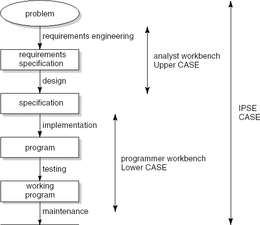
This section is devoted to CASE products that support (parts of) the software development process. Depending on the scope of the set of tools available, such an environment is called an Analyst WorkBench (AWB), a Programmer WorkBench (PWB), a Management WorkBench (MWB), or an Integrated Project Support Environment (IPSE); see also Figure 15.1. The acronym CASE (Computer-Aided Software Engineering) is often used to indicate any type of tool support in the software development process. The qualified terms Upper CASE and Lower CASE refer to tool support during the analysis-design and implementation-test phases, respectively.
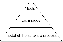
In the ideal case, the choice of a specific set of tools will be made as follows. First, a certain approach to the software development process is selected. Next, techniques are selected that support the various phases in that development process. As a last step, tools are selected that support those techniques. Some steps in the development process may not be supported by well-defined techniques. Some techniques may not be supported by tools. Thus, a typical development environment will have a pyramid shape as in Figure 15.2.
In practice, we often find the reverse conical form: a barely developed model of the development process, few well-defined techniques, and a lot of tools. In this situation, the benefits of the tools are limited at best. To paraphrase the situation: for many a CASE, there is a lot of computer-aided and precious little software engineering.
Analyst workbenches serve to support the activities in the early phases of software development: requirements engineering and (global) design. In these phases, analysis and design data is gathered. Often, a graphical image of the system is made, for instance in the form of a set of UML diagrams. From a practical point of view, important problems concern the drawing and redrawing of those diagrams and guarding the consistency and completeness of the data gathered. AWB tools specifically address these points.
The kernel of an AWB is a database in which the information gathered is stored. The structure of the database can be free or it can be derived from the techniques supported. The AWB also contains tools to support the following types of activity:
Drawing, changing and manipulation of pictures: This may vary from simple drawing programs that have no knowledge of the pictures' semantics, to programs that have an elaborate knowledge of the semantics of the drawing technique in question. As far as the latter is concerned, we may think of automatic generation of pointers to subpictures, the automatic reconfiguration of pictures to circumvent intersecting lines, and so on. If the drawing technique has been sufficiently formalized, the user support can be comparable to that offered by a syntax-directed editor for programming languages.
Analysis of data produced, as regards consistency and completeness: The possibilities of doing this are strongly dependent upon the degree to which the drawing technique itself imposes strict rules. There is a choice as to when this checking takes place. If the user is immediately notified when an error is made, there is little chance for errors to cascade. On the other hand, the freedom to 'play' during the exploratory development stages is also limited. If checking is done at a later stage, the user may continue on the wrong track for quite a while before detection, and it then becomes more difficult to identify the proper error messages.
Managing information: A prime example is managing requirements. A simple way is to store them in a plain text document. More advanced tools allow for maintaining relations between requirements, tracing requirements to design documents, detecting and handling conflicts, and so on.
Generating reports and documentation: It is important to be able to adapt the precise form of reports and documentation to the requirements of the user. For instance, internal standards of some organization may enforce certain report formats. It should be possible to configure the tools to adhere to these standards.
Further tools of an AWB may support, amongst others, prototyping, the generation of user interfaces, or the generation of executable code. (Post et al., 1998) found that users perceive two types of (Upper-CASE) tool: those that are good at supporting analysis and design tasks and those that are good at code generation and prototyping. Apparently, the tools tend to emphasize one of these uses.
A programmer workbench consists of a set of tools to support the implementation and test phases of software development. The term originated in the UNIX world (Dolotta et al., 1978). The support offered by UNIX mainly concerns these types of activity. Many programming environments constructed around a certain programming language also support these phases in particular. In a PWB, we find tools to support, among others:
editing and analysis of programs;
debugging;
generation of test data;
simulation;
test coverage determination.
The tools that support teamwork on large projects deserve our special attention. In a typical environment, a group of programmers will be working on the same system. The system will have many components, developed, tested, and changed by different people. During the evolution of the system, different versions of components will result. Automatic support for the control of such a set of components, both technically and organizationally, is a sheer necessity.
One of the early systems for configuration control is the source code control system (SCCS), originally developed for IBM OS and best known from UNIX. SCCS enables the user to keep track of modifications in files (which may contain such diverse things as program code, documentation, or test sets). The system enables the user to generate any version of the system. New versions can be generated without old versions being lost. Important aspects of SCCS are:
no separate copies of versions are kept: only the modifications (so-called deltas) to previous versions are stored;
access to files is protected: only authorized users can make changes;
each file is identified by author, version number, and date and time of modification;
the system asks the user for information on the reason for a change, which change was made, where, and by whom.
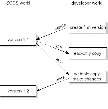
Figure 15.3 illustrates the main operations provided by SCCS. Within SCCS, all information is kept in s-files. The operation create creates the s-file for the first time. If the original file is named prog, then the SCCS file is named s.prog. The operation get yields a read-only copy of the file requested. This read-only copy can be used for compiling, printing, and so on. It is not intended to be edited. The operation edit retrieves a copy to be edited. SCCS takes care of protection in the sense that only one person can be editing a file at one time. Finally, the delta operation stores the revised version of the file edited.
Versions of SCCS files are numbered, 1.1, 1.2, 1.3, 2.1, etc. The number to the left of the period is the major version number (release number). The number to the right of the period is the minor version number. The first version is numbered 1.1. By default, get and edit retrieve the latest version of a file, while delta results in an increase of the minor version number. If an older version is required or the major version number is to be increased, this must be specified explicitly.
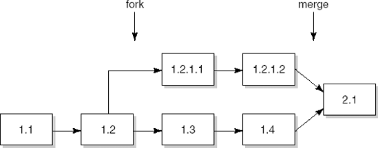
The above scheme results in a linear sequence of versions. SCCS also provides the possibility of creating branches (forks), as illustrated in Figure 15.4. For example, starting from version 1.2 we may create versions 1.3, 1.4, etc to represent normal development of a system component, and versions 1.2.1.1, 1.2.1.2, etc to represent bug fixes in version 1.2. In SCCS, the merging of development paths must be done manually.
When different versions of the same system are maintained in this way, the need to automate the construction of new executable versions arises. Make is a tool that does this (Feldman, 1978). Make uses a description of the various components of a system and their mutual dependencies. When generating a new executable system, Make inspects the date and time of the latest changes to components and only recompiles components when needed (i.e. components that have been changed since the last compilation). A tool such as Make not only saves machine time, but also ensures that the most recent version of each component is used.
The basic functionality of configuration control systems has not fundamentally changed since the development of SCCS in the early 1970s. Rather than keeping a copy of each version, SCCS and similar systems only keep track of what has changed from the previous version (the deltas). Nowadays, disk storage is not an issue and many software configuration systems use simple zip-like compression instead of deltas. Additional features offered in present-day systems are mainly directed at increasing the flexibility and usability of such systems:
The ability to symbolically tag file versions: If the repair of some bug requires changes in a number of modules, each of these revised modules may be given the same tag, say
bug27. In a subsequent build of the system, this tagbug27may then be used to reference file versions in which this bug has been taken care of. This frees the user from the need to remember that the bug concerns version 1.12 of module A, version 1.3.1.7 of module B, etc.The ability to automatically merge branches: This is by no means a foolproof operation and should be used with care. The possibility of merging branches hinges on the availability of appropriate merge tools. If changes are made in disjoint parts of a file, merge tools can generally merge these changes fully automatically.
Flexible support for multiple developers working on the same system: In SCCS, only one person can be editing a file at a time. This rather restrictive scheme is known as reserved checkout. It may unnecessarily restrict the work in a team. For example, one developer may check out a file he is not going to work on until next week. However, the fact that he did so prevents other developers from working on that file during this week. In another model, known as unreserved checkout, each developer has a working copy of a file. After a while, one developer writes back his updated copy of that file, and other developers will be notified if they want to do the same. These other developers will then, one by one, have to merge their changes with the already updated copy.
Management of workspaces: Checked-out files are put in a workspace. This may be as simple as the home directory of a developer, or more complex and supported by additional tools. For instance, as well as the files a developer is about to change, files that are needed to compile and test changes may be automatically downloaded.
Support for communication within a development team: For example, if one developer checks out a file someone else is already working on, he may be given a notification of this, so that the developers can start a dialog and coordinate their activities. The latter type of support connects the pure archival function of configuration control systems with the communication and coordination functions of workflow management systems.
Language-centered environments, as discussed in Section 15.2, support the individual developer. These environments are dominated by issues of software construction. The emphasis is on tools that support software construction: editors, debuggers, compilers, etc. Toolsets that offer configuration management and system build facilities such as those offered by SCCS and Make can be classified as belonging to the family model of software development environments: a great deal of freedom is left to individual developers, while a number of rules are agreed upon to regulate critical interactions between developers.
Most programmer workbenches offer this family type of support. For example, Make assumes that files whose names end in .c are C source files. Members of the development family follow this rule and may even have agreed upon further naming conventions. The development environment however has no way of enforcing those rules. It is up to management to make sure that the rules are followed.
A management workbench contains tools that assist the manager during planning and control of a software development project. Example tools in an MWB include:
Configuration control Besides the control of software components as discussed in the previous section, we may also think of the control of other project-specific information, such as design and analysis data, or documentation. An essential aspect of this type of configuration control concerns the control of change requests. Changes are proposed, assessed, approved or rejected, given a priority and cost estimate, planned, and executed. The corresponding procedures are described in a configuration control plan. The administration and workflow of those change requests may well be supported through a tool. See also Chapter 4.
Work assignment Given a number of components, their mutual dependencies, and resources needed (both people and hardware), tools can be used to determine critical paths in the network of tasks, and work packages may be assigned accordingly. This is a central feature of process-centered environments; see Section 15.4.
Cost estimation Various quantitative cost-estimation models have been developed. These models yield cost estimates, based on project characteristics. Tools have been developed that assist in gathering quantitative project data, calibrating cost estimation models based on this data, and making cost estimates for new projects.
An integrated project support environment (IPSE) is meant to support all phases of the software life cycle. Thus, such an environment has to contain the various tools discussed in the previous sections. Environments that span the complete life cycle usually emphasize the support of either front-end activities (analysis and global design — Upper CASE) or back-end activities (implementation and testing — Lower CASE). They then contain tools specifically geared at supporting tasks from the corresponding part of the life cycle, augmented by more general support for the other phases (such as for editing, text processing, or database access).
When developing an IPSE, we may strive for either a strong or a weak integration of its tools. A strong integration, as realized in the language-centered environments discussed in Section 15.2, has both advantages (such as better control capabilities) and disadvantages. One disadvantage is that such an IPSE tends to be less flexible. If the tools are not integrated, as in UNIX, there is more flexibility. On the other hand, more stringent management control is then needed.
We may also look for intermediate forms. For example, all objects may be stored in the UNIX file system, controlled by SCCS, and the relationships between objects may be represented using a relational database system.
The heart of an integrated environment is the data repository, containing the information shared between the tools that make up the environment. The constraints imposed on the structure of this repository mirror the degree to which the tools are integrated. A stricter integration of tools allows for a stricter definition of the structure of the data they share, and vice versa.
In a process-centered software engineering environment (PSEE), a description of the software development process is shared by the tools that make up the environment. Not surprisingly, developments in process-centered environments are closely tied to developments in process modeling, and vice versa. For example, the kinds of description used in process modeling (state transition diagrams, Petri nets, and so on) are also the formalisms used in PSEEs. Process modeling is discussed in Section 3.7.
As with an integrated environment, a process-centered environment may cover the complete life cycle. As with an IPSE, a PSEE tends to be geared towards supporting tasks from a specific part of the software development life cycle. Since back-end activities (implementation and testing) are somewhat easier to structure and formalize, work on process modeling and PSEEs has concentrated on modeling and supporting back-end activities.
Figure 15.5 gives a model of the process of conducting a code review. The notation is that of Petri nets. In Section 3.7, this same figure was used to explain the role of different formalisms in process modeling. Here, we discuss its role in a process-centered software engineering environment.
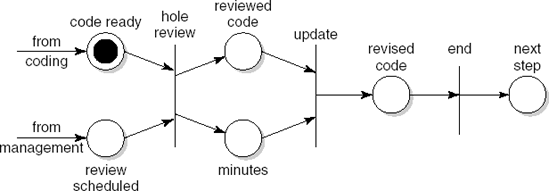
If the developer indicates that some piece of code is ready for review, the environment is notified and comes into a state as indicated in Figure 15.5. Parallel to the coding activity, management schedules a review meeting. Once this is done, the place[29] labeled review scheduled is marked. The support environment then 'knows' that the review can be held and may offer support for doing so. In this way, the environment guides the developers and other participants through the steps of the review process, alerts them when certain actions are required, maintains status information of code products and other pieces of information, etc. Thus, PSEEs provide support for software development by automating routine tasks, invoking appropriate development tools, and enforcing rules and practices.
Formal models of a software process are rigid. In practice, this rigidity is a hindrance, since there will always be exceptions. For example, the minutes of a review meeting might get lost, management may decide to skip a certain review meeting, a review meeting may have to be rescheduled because some participant was ill, etc. The Petri model of Figure 15.5 cannot cope with these situations. A number of them can be accommodated by making the model more complex. But the model will never cover all situations. There is thus a need to be able to intervene. Some PSEEs, for example, offer a way of updating process models on the fly. A fully satisfactory solution is difficult to find and the rigidity of formal models is likely to continue to conflict with the requirements of flexibility in process support.
This holds even more where it supports the early stages of software development. A designer or requirements engineer is not helped by an environment that dictates the detailed order of process steps to be taken. Broadly speaking, we may distinguish two types of activity: the unstructured, creative, and cooperative activities that characterize the early stages of software development; and the repetitive and structured activities that characterize the later stages. A similar dichotomy may be observed in PSEEs. Those that focus on the early stages have much in common with groupware and computer-supported cooperative work (CSCW) systems. These PSEEs support coordination of activities, such as access to and sharing of information, and cooperation activities, such as communication between people and scheduling meetings. This type of support is becoming increasingly important in present-day multisite development; see also Chapter 20. PSEEs focusing on the later stages have much in common with workflow management and configuration control systems. Present-day configuration control systems not only offer the basic versioning and access capabilities known from systems such as SCCS (see Section 15.3.2) but they also offer ways to define and enact software configuration tasks and policies. Some even claim that configuration management tools are the 'real' PSEEs (Conradi et al., 1998).
Developments in the area of (integrated) collections of tools move very fast. For many a facet of the software development process, good tools are available. In this chapter, we have discussed the major developments as regards computer-aided software engineering (CASE). We have done so using a simple, one-dimensional classification of CASE products, which expresses the parts of the life cycle they support:
a tool supports one specific task;
a workbench supports a limited set of activities, such as those which comprise the implementation and testing stages;
an environment supports the entire process.
We have further classified environments according to the mechanism that ties together the tools that make up the environment:
In a toolkit, the tools are generally not so well integrated. A toolkit merely offers a set of useful building blocks. UNIX is a prime example of this.
A language-centered environment contains tools specifically aimed at supporting software development in a specific programming language.
An integrated environment contains tools that share information about the resulting product. This information is stored in a data repository, and the tools read and write this repository.
A process-centered environment contains tools that share a description of the software-development process.
Though environments are supposed to cover the entire life cycle, they tend to emphasize certain parts of the process. They then contain tools specifically geared at supporting tasks from that part of the process, augmented by a more general, and often limited, support for the other parts. For example, language-centered environments tend to focus on the implementation and testing stages.
One of the major impediments to the widespread use of tools is their rigidity. Software tools are driven by formal models of what can and cannot be done. A tool for requirements engineering is likely to enforce certain rules of well-formedness on the diagrams it handles. A tool to support the testing process is likely to prescribe a certain order of process steps. The requirements engineer, though, may well want to play with ill-formed diagrams for a while. Likewise, the tester may want to deviate from the pre-established order of steps if circumstances require this. The tension between the demands for flexibility of tool users and those for formality of tool builders is one of the major challenging research themes in this area.
In a retrospective of PSEE research, Cugola and Ghezzi (1998) refer to this tension as the minimalist versus maximalist approaches. In a maximalist approach, the goal is to model all possible situations. A minimalist approach is more lightweight and acknowledges that humans play a decisive role in the decision process. A further corollary is that tools should support cooperation rather than automation.
An interesting open question is whether tools really help. Studies of tool adoption and usage show mixed results. Some conclude that tools offer real improvements, while others conclude that users have not found tools to be helpful. There are definitely certain impediments to tool adoption. Tools cost money, sometimes a lot of money. There is also a learning curve for tool users. Finally, there is quite a gulf between the state of the art as reported in this chapter and actual practice.
For many an organizational problem, automation seems to be the panacea. Likewise, the use of tools is often seen as panacea for our problems in software engineering: CASE as prosthesis. Tools, though, remain mere tools. Within the software development process, other factors play a role as well. If the tools do not fit the procedures used within your organization, they are likely to have a far from optimal effect. Also, tools cannot make up for an ineffective development method or badly qualified personnel. Good people deliver good products and mediocre people deliver mediocre products, irrespective of the tools they use.
An early taxonomy of CASE products is given in (Dart et al., 1987). Fuggetta (1993) extended this framework with a category of 'process-centered environments'. The latter classification is used in this chapter. Additional dimensions for classifying CASE products are given in (Lott, 1993). Lundell and Lings (2004) discuss how perceptions of CASE have changed over the years. The sociological paradigm (individual, family, etc.) for the user scale stems from (Perry and Kaiser, 1991).
(Barstow et al., 1984) is a collection of seminal articles on programming environments, including the UNIX toolkit approach and early language-centered environments such as Interlisp. The Source Code Control System (SCCS) is described in (Rochkind, 1975). The state of the art in configuration management is reflected in (Estublier et al., 2005). Building tools have not changed much since Make (Feldman, 1978). A recent development in this area in the Java world is Ant (Serrano and Ciordia, 2004).
In the 1980s, tool research focused on creating integrated environments. (Tahvanainen and Smolander, 1990) is an annotated bibliography of articles on software engineering environments from that period. Subsequent research in the area of tools focused on PSEEs. The state of the art in this area is reflected in (Fuggetta and Wolf, 1996) and (Ambriola et al., 1997). The case for more flexibility in software engineering environments is made in (Jankowski, 1994), (Cugola et al., 1996), (Jarzabek and Huang, 1998), and (Cugola and Ghezzi, 1998).
Tool integration issues are addressed in (Sharon and Bell, 1995). Tools assessment is the topic of (Software, 1996b). Studies of tool adoption and usage can be found in (Iivari, 1996) and (Post et al., 1998).
What does the acronym CASE stand for?
Define the following terms:
tool,
workbench,
environment.
What are the main distinguishing features of:
a toolkit,
a language-centered environment,
an integrated environment, and
a process-centered environment.
What is the difference between Upper CASE and Lower CASE?
What is the basic functionality of a tool for configuration management?
Discuss the fundamental tension between formality and informality in tools.
Why is the user scale an important issue when considering the adoption of tools?


utilities you use on a regular basis;
utilities you use infrequently or vaguely know about.
Next compare these lists with the manuals describing the environment. What percentage of the environment's functionality do you really need?