Chapter 2
Subsea Field Development
Contents
2.1. Subsea Field Development Overview
2.2. Deepwater or Shallow-Water Development
2.3. Wet Tree and Dry Tree Systems
2.3.1. Wet Tree Systems
2.3.2. Dry Tree Systems
2.3.3. Systems Selection
2.4. Subsea Tie-Back Development
2.4.1. Tie-Back Field Design
2.4.2. Tie-Back Selection and Challenges
2.5.1. Comparison between the Stand-Alone and Tie-Back Developments
2.5.2. Classification of Stand-Alone Facilities
2.6. Artificial Lift Methods and Constraints
2.6.1. General
2.6.2. Gas Lift
2.6.3. Subsea Pressure Boosting
2.6.4. Electric Submersible Pump (ESP)
2.7. Subsea Processing
2.8. Template, Clustered Well System, and Daisy Chain
2.8.1. Satellite Well System
2.8.2. Template and Clustered Well System
2.8.2.1. Clustered Satellite Wells
2.8.2.2. Production Well Templates
2.8.3. Daisy Chain
2.9. Subsea Field Development Assessment
2.9.1. Basic Data
2.9.2. Water-Cut Profile
2.9.3. Process Simulations
2.1 Subsea Field Development Overview
Subsea field development is a long and complicated procedure that begins with the primary survey and ends with the last reservoir recovery.
Figure 2-1 illustrates the life cycle of the development of an oil or gas subsea field. Initially, mapping and reconnaissance are conducted by exploration geologists and geophysicists. They ultimately delineate the development area’s geology based on the data gathered from old wells, seismic analysis, and any other information that is available. The initial issues at this stage concern the following aspects:
• Structure of the basin and the subregional features (i.e., fault and/or fold traps for hydrocarbons);
• The stratigraphy (i.e., whether the reservoir rocks exhibit porosity and permeability);
• The burial history of the basin (i.e., whether the source rocks have been buried sufficiently for hydrocarbon generation).

Figure 2-1 Field Development Life Cycle
By addressing these concerns, investigators may identify and select parts of the larger area for further study and may ultimately generate a prospect evaluation.
After the initial investigations, the reservoir description phase begins, which involves drilling delineation wells and perhaps conducting 3D seismic analyses. This new information allows reservoir engineers and geologists to calculate the volume of oil and/or gas that is present in the reservoir. Then it is time to ascertain the optimum subsea field layout and pipeline route; the production facilities will also be selected based on field layout and installation considerations. After all well and equipment testing, the field begins to produce oil and gas. However, as more and more oil and gas are transported to the host structure from the reservoir, the reservoir pressure will decrease, and need to recovery to keep the production being transported from the reservoir.
This chapter provides guidelines for the main disciplines associated with the development of a field architecture without topside facilities and also for system integration and interfacing, which are the most important parts of a field development project.
When defining a field architecture, the following issues should be considered:
2.2 Deepwater or Shallow-Water Development
Subsea field development can be categorized according to the water depth:
• A field is considered a shallow-water subsea development if the water depth at the location is less than 200 m (656 ft). In practice, shallow water is the water depth within a diver’s reach.
• A field is considered a deepwater subsea development if the water depth ranges between 200 and 1500 m (656 and 5000 ft);
• Ultra-deepwater subsea developments are those in which the water depths are greater than 1500 m (5000 ft).
The difference between shallow-water and deepwater field developments in terms of design considerations are listed in Table 2-1.
Table 2-1. Difference between Shallow-Water and Deepwater Field Developments
| Items | Shallow-Water Development | Deepwater Development |
| Hardware design | Because diver-assisted intervention is possible, an ROV--related structure is not necessary. | Because an ROV assists with all interventions, an ROV-related structure is needed. |
| Mudline trees usually will be used. | Insulation is needed for pipes due to high pressures and temperatures. | |
| A horizontal or vertical tree will be used. | ||
| Installation requirement | Limited by the size of vessel. | More difficult than in shallow water due to higher tension, especially horizontal load. |
| Umbilical design | Smaller umbilicals can be utilized due to the short distance of power transportation. | Umbilicals are bigger and more expensive. |
| Intervention, maintenance, and repair | Diver-assisted intervention is feasible. | Deepwater maintenance and repairs require the use of ROVs for surveys and some repairs. |
| Deepwater subsea developments are high cost and high risk. |
2.3 Wet Tree and Dry Tree Systems
Two kinds of subsea production systems are used in deepwater fields: dry tree systems and wet tree systems, as shown in Figure 2-2.

Figure 2-2 Dry Tree and Wet Tree Systems [1]
For the dry tree system, trees are located on or close to the platform, whereas wet trees can be anywhere in a field in terms of cluster, template, or tie-back methods. Dry tree platforms have a central well bay for the surface trees, providing direct access to the wells for workover and recovery. Tension leg platforms (TLPs) and spars are normally utilized in a dry tree system.
The size of the central well bay on dry tree platforms is dictated by well count and spacing. Topside equipment has to be arranged around the well bay. The surface trees are designed for full reservoir shut-down pressures. A large production manifold is required on deck, and a skiddable rig is required for individual well interventions [1].
For wet tree systems, the Christmas tree and its associated components are exposed to the ambient seabed conditions. In deepwater fields, the wet tree system normally utilizes a remotely controlled subsea tree installation tool for well completions, but for shallow water the diver can assist with installation and operation. Wet tree platforms have a central moon-pool for running marine risers and trees, which might also be preferred for installing other equipment, such as the manifold and blow-out preventer (BOP), if the sizes are suitable. Wet tree systems are suitable for widespread reservoir structures. They provide a degree of vessel and field expansion flexibility with simplified riser interfaces, but at the expense of high drilling and workover costs.
In recent years, operators have been compelled to reappraise their strategy of rapid development in ultra-deepwater areas due to the commercial competitiveness and technical issues related to dry tree versus wet tree systems. Globally, more than 70% of the wells in deepwater developments that are either in service or committed are wet tree systems. These data demonstrate the industry’s confidence in wet tree systems.
Compared to wet tree systems, dry tree systems require motion-optimized hulls to accommodate the riser systems; they are considered to be limited with respect to water depth and development flexibility. Globally, most subsea field developments that are either in service or committed to are wet tree systems. Although widely used for developments in shallow to medium water depths, the dry tree units are still not considered optimum for deepwater and ultra-deepwater situations.
2.3.1 Wet Tree Systems
For wet tree system, the subsea field layout usually comprises two types: subsea wells clusters and direct access wells.
Direct access is only applied in marginal field development. All such developments are usually based on semi-submersible floating production and drilling units (FPDUs) with oil export either via pipeline or to a nearby floating storage and offloading (FSO) unit, providing direct and cost-effective access from the surface to the wells to allow for workover or drilling activities directly from the production support, especially for deepwater interventions.
A subsea cluster of wells gathers the production in the most efficient and cost-effective way from nearby subsea wells, or (when possible) from a remote /distant subsea tie-back to an already existing infrastructure based on either a floating production, storage and offloading (FPSO) or a floating production unit (FPU), depending on the region considered.
Figures 2-3, 2-4, and 2-5 illustrate subsea well clusters and subsea direct-access wells. The subsea tie-back system normally can be regarded as a supplement for subsea cluster well developments, as shown in Figure 2-3.

Figure 2-3 Tie-Back Field Architecture [1]

Figure 2-4 FPU Field Architecture [1]

Figure 2-5 FPSO Field Architecture [1]
The FPU has various ways to export the oil or gas, as shown in Figure 2-6. Typically a barge, semi-submersible, or even a mini-TLP type vessel is used. Figure 2-4 illustrates an FPU field architecture.

Figure 2-6 FPU Connection Module
Figure 2-5 shows a field with an FPSO field architecture. The FPSO usually utilizes a ship- shaped or barge-type vessel as the host structure that is moored either via a turret and weathervaning system to allow for tandem offloading or spread moored with offloading via a distant buoy or still in tandem mode [1].
For both subsea well clusters or subsea direct-access wells, the three main riser options would be vertical top tensioned risers, steel catenary risers, and flexible risers. Pending use of the above field architectures and risers in conjunction with particular flow assurance design criteria, these wet tree system would be the most effective.
2.3.2 Dry Tree Systems
Dry tree system production systems are the main alternative to the subsea well cluster architecture. Their surface well architectures provide direct access to the wells.
Current dry tree system architectures consist of an FPDU hub based either on a TLP, on a Spar, or even (in some cases) on a compliant piled tower (CPT) concept. Alternative concepts in the form of barge or deep-draft semi-submersible (DDF) floaters could also be considered as possible options in some cases but have not yet materialized.
Deepwater surface well architectures in the form of a wellhead platform (WHP or FDU) associated with either an FPSO or an FPU are starting to emerge in other parts of the world (West Africa, Southeast Asia). This type of association between a WHP and an FPSO could also eventually become reality in the Gulf of Mexico as the FPSO concept becomes progressively authorized. Existing (or actually planned) WHP hubs are currently all based on a TLP concept with either full drilling capacities or with tender assistance (mini-TLP). However, other concepts such as Spar, barge, or deep-draft semi-submersible units could also be considered as alternatives.
Risers for dry completion units (DCUs) could be either single casing, dual casing, combo risers (used also as drilling risers), or tubing risers and could include a split tree in some cases.
The riser tensioning system also offers several options such as active hydropneumatic tensioners, air cans (integral or nonintegral), locked-off risers, or king-post tensioning mechanism.
2.3.3 Systems Selection
A thorough and objective assessment of wet and dry tree options should be conducted during the selection process and include costs, risks, and flexibility considerations to ensure that the development concept that best matches the reservoir characteristics is selected.
Operators are often faced with the problem that commercial metrics, such as capital cost or net present value (NPV), are inconclusive. In the base case of developments examined, the commercial metrics are shown to generally favor the wet tree concept over the life cycle of the system, but the benefit over the dry tree concept is not overwhelming. When this is the case, the operator must thoroughly assess other important differentiators before making the final selection.
The best tree system matchup with the reservoir characteristic can be selected by experience and technical analysis. The following are the basic selection points:
• Economic factors: Estimated NPV, internal rate of return (IRR), project cash flow, project schedule, and possibly enhanced proliferation control initiative (EPCI) proposals (if any available at the time of the selection) will most certainly be the key drivers of this choice.
• Technical factors: These factors are driven primarily by reservoir depletion plans and means, field worldwide location, operating philosophy, concept maturity and reliability, feasibility, and industry readiness.
• External factors: These factors are in the form of project risks, project management, innovative thinking, operator preferences, and people (the evaluation method may vary between each individual).
2.4 Subsea Tie-Back Development
Subsea developments only made sense for big reservoirs before, because the CAPEX and OPEX costs are high and it is difficult to justify the return versus the risk. So, in some cases, the small marginal oil fields are normally ignored. In recent years, subsea tie-backs were set to become popular in the development of marginal oil and gas reserves in an effective and economical way. Operators began to realize that the overall capital expenditure can be decreased by utilizing the processing capacity on existing platform infrastructures, rather than by continuing to build new structures for every field. Thus much smaller accumulations can be developed economically.
Generally subsea tie-backs require significantly lower initial investments, compared with developments using FPSOs or other fixed installations. The economics of having a long tie-back are governed, however, by a number of factors specific to that field:
• Distance from existing installation;
• Recoverable volumes, reservoir size, and complexity;
• Tariffs for processing the produced fluids on an existing installation;
• The potentially lower recovery rates from subsea tie-backs versus stand-alone development, due to limitations in the receiving facility’s processing systems;
• The potentially higher recovery rates from platform wells, due to easier access to well intervention and workovers.
The host of subsea tie-backs can be categorized as follows:
• Tie-back to floating production unit (see Figure 2-7);
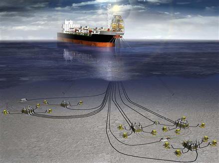
Figure 2-7 Subsea Tie-Back to FPSO [2]
• Tie-back to fixed platform (see Figure 2-8);

Figure 2-8 Subsea Tie-Back to TLP [2]
• Tie-back to onshore facility (see Figure 2-9).

Figure 2-9 Subsea Tie-Back to Onshore Facility [3]
2.4.1 Tie-Back Field Design
A subsea tie back system generally includes a subsea wellhead and a flowline to an existing production platform for example. Some serious limitations of flow assurance are expected with a longer subsea tie-back, such as hydrate formation induced plugging of the flowline due to the heat loss to the environment and therefore a decrease of temperature along the flowline.
The conventional remedial methods include thermal insulation of flowlines or injection of chemical inhibitors to prevent the formation of hydrates (refer to Part II, flow assurance part of this book). Such chemicals can be transported from the host platform to the subsea wellhead with an umbilical, and can be injected into the flowline at the wellhead. The umbilical can also be used to control the subsea wellhead. The cost of such umbilical is typically very high, and the economics of a subsea tie-back is often threatened by the excessive umbilical cost for tie-back distances greater than 30 km.
An alternative development scenario of flow assurance consists of providing a small offshore platform near the wellhead with remote control from the host platform and injection of chemical stored on the small offshore platform via a short umbilical connected to the subsea system. The presence of a platform directly above the wellhead enables pig launcher capabilities and well logging tools support.
When multiphase hydrocarbon flow is expected in the flowline, the tie-back distance is limited because of flow assurance problems. Current technological developments are aimed at providing subsea separation facilities on seafloor to separate the fluid into hydrocarbon liquid, gas and water, allowing hydrocarbons to flow over a longer distance.
Subsea equipment such as subsea pumps may be required to increase the pressure of fluid and assist flow assurance over the tie-back length. Such pump system also requires power which can be provided by a surface facility.
Dual-flowlines as shown in Figure 2-10 are used widely in the subsea tie-back system to provide a circuit for pig to start from the production platform, go through the flowlines to remove the solids in the flowlines, such as wax, asphaltene, sand, and return to the production platform.

Figure 2-10 Typical Tie-Back Connections [4]
2.4.2 Tie-Back Selection and Challenges
Advances in flow assurance and multiphase transport now allow the use of tie-backs over much longer distances, while the introduction of subsea processing will strengthen the business case for subsea tie-backs in future field developments. However, we can try to choose the best development plan, based on an overall consideration of the following factors:
• Cost: Lowest life-cycle cost (i.e. lower CAPEX and OPEX);
• Safety: Safety of personnel and other stakeholders in construction and operation;
• Environment: Impact of development on the environment;
• Technology innovation or transfer: Trial of new technology or transfer of existing technology and know-how;
• Capacity utilization: Use of existing infrastructure, facilities, and elongation of useful life;
• Recoverable volumes, reservoir size, and complexity;
• Tariffs for processing the produced fluids on an existing installation;
• The potentially lower recovery rates from subsea tie-backs versus stand-alone development, due to limitations in the receiving facility’s processing systems;
• The potentially higher recovery rates from platform wells, due to easier access to well intervention and workover.
Many marginal fields are developed with subsea completions and with the subsea tie-back flowlines to existing production facilities some distance away. Subsea tie-backs are an ideal way to make use of existing infrastructure. Long tie-back distances impose limitations and technical considerations:
• Reservoir pressure must be sufficient to provide a high enough production rate over a long enough period to make the development commercially viable. Gas wells offer more opportunity for long tie-backs than oil wells. Hydraulic studies must be conducted to find the optimum line size.
• Because of the long distance travelled, it may be difficult to conserve the heat of the production fluids and they may be expected to approach ambient seabed temperatures. Flow assurance issues of hydrate formation, asphaltene formation, paraffin formation, and high viscosity must be addressed. Insulating the flowline and tree might not be enough. Other solutions can involve chemical treatment and heating.
• The gel strength of the cold production fluids might be too great to be overcome by the natural pressure of the well after a prolonged shutdown. It may be necessary to make provisions to circulate out the well fluids in the pipeline upon shutdown, or to push them back down the well with a high-pressure pump on the production platform, using water or diesel fuel to displace the production fluids.
Subsea long tie-back developments will be utilized widely in the future with the advent of new technology such as subsea processing and subsea electrical power supply and distribution.
2.5 Stand-Alone Development
Stand alone field development needs to construct a new host platform. Installation of new infrastructure in deep water is exceedingly expensive. Using the existing infrastructure is the first consideration for starting a new development. This includes existing production platforms, pipelines and wells. Figure 2-11 illustrates a typical stand-alone field development.

Figure 2-11 Typical Stand–alone Field Development
(Courtesy SapuraAcergy)
Following issues are the main considerations for a stand-alone field development:
• Well groupings. Clustering wells or installing well templates;
• Optimizing flowline configuration;
• Possible needs for subsea production boosting or pumping as part of the initial development or future needs.
Well grouping scenarios and location should be determined according to the reservoir data and drilling engineering. Types of wells and their locations can be determined once the reservoir is mapped and the number of wells is created according to the reservoir model. Wells are typically grouped as follows:
• Satellite wells: typically used for small filed development requiring few wells, for example, concept of tie-back to the existing structures;
• Cluster wells; common concept for a stand-alone field development. Normally there are 3 to 8 subsea Xmas trees located in the surrounding of a central production manifold, as shown in Figure 2-12;

Figure 2-12 Typical Cluster Wells Concept
(Courtesy Technip)
• Template wells; the subsea wells are grouped closely together. This concept usually utilizes a template in which the well guide bases and the manifold are integrated. Subsea Xmas trees are landed and locked on each slots of the template;
2.5.1 Comparison between the Stand-Alone and Tie-Back Developments
For the stand-alone concept, the main subsea structure is normally constructed as a drilling platform and will also be used as a production platform. The structure acts as a stabilizer and conditioning for the subsea well production. Subsea risers, helicopter landing pads, and mooring facilities for boats are necessities and supported by the structure. Table 2-2 summarizes the differences between the tie-back development and the stand-alone development.
Table 2-2. Comparison between the Stand-alone and Tie-back Developments
| Concept | Features |
| Subsea tie-back development | |
| Stand-alone development |
2.5.2 Classification of Stand-Alone Facilities
The stand-alone facility is a host facility that receives the production from a field. Figure 2-13 illustrates four typical host facilities, which vary from the wellhead and process platform receiving production from surface trees to subsea trees of subsea tiebacks. The host facility could even be a land based facility receiving production from a subsea tieback to beach.

Figure 2-13 Typical Host Faculties
The stand-alone facilities used in subsea field development can be divided into two categories: fixed platforms and floating systems. Bottom of the fixed platform is located on the seabed to support the decks to be fixed above the water surface. The floater systems have to be moored in place with tendons or wire ropes to keep connection with the subsea systems below. Floating systems can be used from 300 m to more than 1500 m water depth. Following are the definitions and main features of the host facilities.
• Fixed platforms: fixed platforms are built on concrete or steel jackets which are directly anchored on the seabed. Various types of platforms, e.g. concrete caisson, and steel jacket are used for this concept. A jack up platform is also used for the production of oil and gas. Fixed platforms are usually installed in the water depth within 500 m;
• TLP: tension leg platform (TLP) is a vertically moored floating structure. A group of tethers called “leg” is used to moor the each corners of the floating structure. The lateral movement is allowed, but vertical movement is prevented by the legs. The TLP can be used in the water depth from 300 m to 1500 m. Both dry trees and wet trees can be used for the TLP production system;
• SPAR: the Spar platform utilize a large-diameter, single vertical cylinder buoy floating on the sea water surface to support the decks. Spars can be used in the water depth around 1500 m;
• Semi-submersible platforms: Semi-submersible platform can be operated for drilling, subsea equipments installation and oil/gas production.
• FPSO: a floating vessel for the processing and storage of oil and gas. The FPSO is designed to receive the production oil and gas from nearby platform or subsea production systems. The crude oil can be offloaded onto a tanker or transported through pipelines.
Comparison of the wave responses of the floaters are as following:
• FPSO is very responsive because of large water plane, large surface area (beam seas), and softer restoring force;
• Semi-submersible has a slow natural period due to softer restoring force, vortex-shedding, shallow drafts increase pitch/roll response;
• SPAR has a slow natural period due to softer restoring force, vortex shedding, deep draft reduces pitch/roll response;
• TLP has a short natural period due to highly tensioned tendons and limited water plane;
2.6 Artificial Lift Methods and Constraints
2.6.1 General
Artificial lift is widely used in the shallow water of the Gulf of Mexico, but its use in deepwater (>1,000 ft) is limited. However, most deepwater oil fields ultimately require the artificial lift to maintain the production flow and achieve economic objectives. Planning for an artificial lift in deepwater is critical, as the environment is operationally more difficult and economically more challenging.
The following are the main artificial lift methods:
2.6.2 Gas Lift
Gas lift (GL) is a predominant artificial lift method used in the offshore environment to date; however, as operators progressively move into deepwater, GL applications become more limited due to higher operating pressures and ESPs applications become more suitable. Figure 2-14 shows a typical subsea gas lift system.

Figure 2-14 Configuration of Typical Subsea Gas Lift System
(Courtesy Shell E&P)
The selection and determination of the gas lift system depends on:
The designs of gas lift for subsea wells have several requirements that are not normally encountered in the designs of traditional gas lift. First, the cost of intervention in a subsea well is considerably higher than for a traditional completion, the subsurface gas lift equipment must be designed with special attention in reliability and longevity. Secondly, the sizing of the port in the operating valve must anticipate production conditions for the life of the well. Figure 2-15 shows the details of a subsea gas lift in downhole.

Figure 2-15 Details of Gas Lift in Downhole
(Courtesy Curtin University)
The design of gas lift system involves two key parameters: gas lift volume and gas lift pressure. Gas lift volume is the total requirement for the field determined by individual well requirements. Production will increase as a function of lift gas volume until a point of maximum production is reached. Gas lift pressure should be determined carefully since this parameter will influence the system operating pressure, material and equipment specification of the well system.
2.6.3 Subsea Pressure Boosting
Some reservoirs have sufficient pressure to push the production fluid from the reservoir to the platform without the use of downhole artificial lift. However, due to the reduction of the reservoir pressure after a long time production, or because of ultra-deepwater light-oil and deepwater heavy-oil reservoirs having pressure that is near hydrostatic pressure, it is quite difficult to produce the fluids to the sea surface.
Subsea boosting as shown in Figure 2-16 reduces or eliminates the backpressure on the wells resulting from the riser hydrostatic head and the riser and flowline pressure drop caused by high viscosity. The pressure increase between the output of the boosting and the backpressure on the well will increase the flow from the well. Components of a subsea boosting station may include:
• Subsea gas compressor, normally used for gas re-injection into the reservoir for pressure maintenance;
• Subsea multiphase pump, used for reduce the back-pressure on wellheads thus increase the transport distance;
• Subsea wet gas compressors, used for gas transportation to remote offshore host facilities or onshore factory;

Figure 2-16 Subsea Pressure Boosting Pump
(Courtesy Aker Solutions)
Subsea boosting may require high consumption of the electric power during the production thus the power sources should be considered.
Subsea pressure boosting system enables longer subsea tiebacks, which potentially could enable the economics of exploiting small, remote, marginal fields. Subsea separation could provide an economic alternative for de-bottlenecking existing surface process facilities, allowing better utilization of these installations by adding new subsea tiebacks which currently would not be economic to develop. Subsea gas separation may allow oil and gas to be separated at the seabed and be transported to different production facilities, which may solve flow assurance problem due to low temperature at seabed.
2.6.4 Electric Submersible Pump (ESP)
Due to the reduction of the driving force which lifts the reservoir from downhole naturally, pumps were commonly used to increase the backpressure for production. The electric submersible pump (ESP) is an effective and economical method of lifting large volume of the fluids from downhole under different well conditions. ESP system requires a large electricity supply, but it is less complex and more efficient than delivering gas to gas lift systems.
An ESP system may include following components:
Different from the surface pump system, the ESP systems are particularly designed to be immersed in fluid. It can be either located in a well or on the seabed. The ESP motors are pressure balanced with the environment, whether that is downhole pressure or water pressure in subsea conditions.
Optional components of the ESP system may include tubing joints, check valve, drain valve, downhole pressure and temperature transmitters, etc. Figure 2-17 shows a typical ESP configuration in downhole.

Figure 2-17 Typical Downhole ESP Configuration
(Courtesy Schlumberger)
The selection of ESP types mainly depends on the well fluid properties. Following are the three major types of ESP applications:
The pump rate is a function of the rotational speed, the number of stages, the dynamic head acting against the ESP and the pumped fluid viscosity. These factors dictate the differential pressure across a pump system, and therefore the flow rate. However, for a given pump, there is an optimal design flow rate that maximizes pump efficiency and run life. Figure 2-18 shows the operating range recommended by ESP manufacturers.

Figure 2-18 Pump Performance Curve
(Courtesy Schlumberger)
Sizing of ESP is based on predicted completion performance, or flow rate. This usually involves examination of the well inflow performance relationship (IPR), which describes the production response to changes in bottomhole pressure (BHP).
Data required for calculation and sizing of ESP includes well data, production data, well fluid conditions, power sources and possible problems etc. Calculations for designing an ESP system include:
2.7 Subsea Processing
Subsea processing (SSP) can be defined as any handling and treatment of the produced fluids for mitigating flow assurance issues prior to reaching the platform or onshore. This includes:
The benefits of introducing subsea processing in a field development could be [4]:
• Reduced total CAPEX, by reducing the topside processing and/or pipeline CAPEX;
• Accelerated and/or increased production and/or recovery;
• Enabling marginal field developments, especially fields at deepwater/ultra-deepwater depths and with long tie-backs;
• Extended production from existing fields;
• Enabling tie-in of satellite developments into existing infrastructure by removing fluid;
Subsea boosting, as explained in an earlier section, is one means of increasing the energy of the system.
Subsea separation can be based either on two- or three-phase separation:
• Two-phase separators are used for separation of any gas–liquid system such as gas–oil, gas–water, and gas–condensate systems.
• Three-phase separators are used to separate the gas from liquid phase and water from oil.
As can be seen from Figure 2-19, the technology and products required for subsea boosting and water removal are available and in operation, while three-phase separation and subsea gas compression still require some qualification before being put into operation.

Figure 2-19 Subsea Separation Development [9]
Thus, a three-phase separator is useful for the crude consisting of all three phases, namely, oil, water, and gas, whereas a two-phase separator is used for the system consisting of two phases such as gas–oil, gas–water, or gas condensate. Further, subsea separation could have a positive effect on flow assurance, including the risk related to hydrate formation and internal corrosion protection derived from the presence of the produced water in combination with gas.
As opposed to the traditional methods of processing reservoir fluids at a process station, subsea processing holds great promise in that all of the processing to the point where the product is final salable crude is done at the seabed itself. This offers cost benefits and also improves recovery factors from the reservoir. Other advantages include a lesser susceptibility to hydrate formation and lower operating expenditures.
Table 2-3 summarizes the classification of subsea processing systems. Characteristics, equipment, water disposal, and sand disposal are compared for four types of subsea processing systems.
Table 2-3. Classification of Subsea Processing Systems [10]

2.8 Template, Clustered Well System, and Daisy Chain
Subsea production equipment can be configured in multiple ways based on the field specifications and operator’s approach to operation.
Field development planners need to work closely with the reservoir and drilling engineers early in the planning stages to establish a good well location plan. Once the reservoir is mapped and reservoir models created, the number of wells, types of wells, and their locations can be optimized. Well layout is usually an exercise of balancing the need to space the wells out for good recovery of the reservoir fluids against the cost savings of grouping the wells in clusters. Add to this the consideration of using extended reach wells, and the number of possible variables to consider becomes great. A further consideration, reservoir conditions permitting, is the use of fewer, high production rate wells through horizontal well completions or other well technology. Here again, there are cost trade-off considerations.
2.8.1 Satellite Well System
A satellite well is an individual subsea well. Figure 2-20 illustrates a typical satellite tie-back system. Satellite wells are typically used for small developments requiring few wells. Often the wells are widely separated and the production is delivered by a single flowline from each well to a centrally located subsea manifold or production platform. Various field layouts must be examined. This evaluation must involve hydraulic calculations and cost sensitivity analyses taking into consideration flowline cost, umbilical cost, and installation cost and flow assurance issues.

Figure 2-20 Typical Satellite Tie-Back System [2]
2.8.2 Template and Clustered Well System
If subsea wells can be grouped closely together, the development cost will usually be less than that for an equivalent number of widely dispersed wells. Well groupings may consist of satellite wells grouped in a cluster, or a well template, in which the well spacing is closely controlled by the template structure. Figure 2-21 shows a typical manifold cluster layout.

Figure 2-21 Typical Manifold Cluster Layout [2]
2.8.2.1 Clustered Satellite Wells
Clustered satellite subsea well developments are less expensive than widely spaced satellite wells mainly because of flowline and control umbilical savings. If several satellite wells are in proximity to one another, a separate production manifold may be placed near the wells to collect the production from all of the wells and deliver it in a single production flowline that is connected to the production facility. In addition, a single umbilical and umbilical terminal assembly (UTA) can be used between the well cluster and the production platform. Figure 2-22 shows a field with eight clustered satellite wells, two subsea production manifolds, and a production umbilical and UTA.
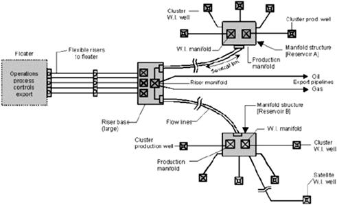
Figure 2-22 Clustered Well Systems [11]
In the case of clustered satellite wells, wells may be placed from several meters to tens of meters from one another. The wider well spacing is often dictated by a desire to be able to position the drilling rig over one well without imposing dropped object risk on adjacent wells. It is hard to precisely control the spacing of individual satellite wells, so crossover piping and control umbilicals must be able to accommodate the variations in spacing.
2.8.2.2 Production Well Templates
A template is a seabed structure that provides guidance for drilling and/or other equipment. It also works as the structural framework supporting other equipment, such as manifolds, risers, wellheads, drilling and completion equipment, and pipeline pull-in and connection equipment. The structure should be designed to withstand any load from thermal expansion of the wellheads and snag loads on the pipelines. Production from the templates may flow to floating production systems, platforms, shore or other remote facilities.
The production well template is used to support a manifold for produced fluids. Wells would not be drilled through such a template, but may be located near it or in the vicinity of the template.
The clustering wells can also be arranged by means of a well template. Well templates are structural weldments that are designed to closely position group of well conductors. The well template is typically used to group several subsea wells at a single seabed location. Apart from reservoir considerations, the number of wells in a well template is limited by the size of the well template that can be handled by the installation vessel. Small templates are usually deployed from the drilling rig. Larger ones may require a special installation vessel with heavier lift capacity or better handling characteristics.
The advantages of the production well template compared to the Clustered satellite Wells are summarized as,
2.8.3 Daisy Chain
A daisy chain configuration connects wells in serious, one after the other by flowlines. The flowline can be either connected to the wells by subsea jumpers, or directly connected to the flowbase of the wells if applicable. Figure 2-23 shows a flowline loop connected to the individual subsea wells along its route, which forms the daisy chain layout. The daisy chain field layout is considered as an economic solution comparing to the cluster manifold layout in case there are several satellite wells e.g. from different marginal fields.

Figure 2-23 Typical Manifold Daisy Chain Layout [2]
Typical example of daisy chain field architecture is Canyon Express field which is located in GoM. This project involvs 10 subsea wells in three different deepwater fields. Staring from the Canyon Station platform, one flowline connects 2 wells in the first field, 2 in the second, and is ended by a sled, which is then connected to the third field by a subsea jumper. Another flowline connects 2 wells in the third field, 2 in the second and the remained 2 wells in the first and finally tied back to the platform. These dual flowlines formed a daisy chain piggy loop.
The daisy chain approach of Canyon Express not only makes use of flowline and equipment already used and paid for, but also saves on the capital expenses comparing to a cluster manifold solution according to a conceptual study made in the early phase of the project.
Typical features of daisy chain field architecture include:
• Inline sleds may be installed at each well location thus Xmas trees can be connected to the flowline by means of jumpers;
• Subsea multiphase flow meters may be required to ensure accurate flow allocation among different wells;
• Flow assurance analysis is key in formulating the production envelop for the daisy chain flowlines;
• Subsea chokes may be necessary on each well/Xmas Tree;
• Round-trip pigging is possible to ensure timely removal of wax build-up in the flowline
2.9 Subsea Field Development Assessment
For subsea field development, field layout designs are selected based on historical data obtained from other projects, and various brainstorming and discussion sessions with teams from all other subdisciplines. Critical design factors may consist of, but are not limited to, the following [4]:
• Well placement and completion complexity;
• Flexibility of field expansion;
• Ease of construction and fabrication for the subsea hardware;
• Intervention capability (easy, moderate, or difficult to intervene);
• Rig movement (offset from mean under extreme environmental conditions);
• Installation and commissioning, such as ease of installation and commissioning, flexibility of installation sequence;
The inputs from the entire project team are used to assign percentage weights to each of these design factors. Normally, all of the various types of field layout designs, such as the subsea tie-back, subsea stand-alone, or subsea daisy chain, can be applied in the field. Reliability, risk assessment, and economic balance are the dominant factors when deciding what kinds of field layout will be chosen.
The following material presents an overview of the available means of adding energy to the production fluid and assessing the best location for the artificial lift to be introduced in a generic deepwater field development. The objectives are:
• To evaluate the artificial lift options including lift gas, electrical motor-driven pumps (ESPs or multiphase pumps) and hydraulic submersible pumps (HSPs);
• To determine the best location (riser base, subsea manifold, or downhole) for artificial lifts using lift gas;
• To determine the best location for installing electrical motor-driven pumps for artificial lifts (ESPs downhole versus multiphase pumps at subsea manifold or riser base);
• To determine the best configuration (open loop versus closed loop) for installing an HSP in a riser in conjunction with coiled tubing for artificial lift.
Figure 2-24 shows an overview of deepwater field development. An example is given in the following sections to show how to calculate and analyze a field development.
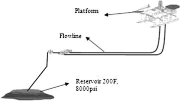
Figure 2-24 Overview of Deepwater Field Development [12]
2.9.1 Basic Data
Reservoir
• Reservoir pressure maintenance by water injection.
• True vertical depth (TVD) = 11,000 ft from mudline;
• Tubing size = 5.5-in. OD (0.36-in. WT);
• Kick-off point = 2,000 ft below mudline;
Subsea Development
• Subsea well completion, dual flowlines, three identical wells per flowline;
• Tie-back distance from subsea manifold to topsides (flowline + riser) of 25,000 ft;
• Steel catenary riser, pipe-in-pipe configuration considered for both riser and flowline with an assumed U value of 0.2 Btu/(ft2 hr °F);
• Seabed terrain assumed to be flat;
• Typical environmental conditions including seawater temperature profile and air temperature were used;
• Riser/flowline roughness = 0.0018 in.;
• 10- and 12-in. nominal riser/flowline sizes were evaluated.
A reservoir’s inflow performance relation is achieved by using Fetkovick’s equation:
![]()
where
![]()
The following slope factor and intercept factor has been selected: n = 0.82, C = 0.35.
The productivity index for the selected inflow performance relation with a wellbore flowing pressure of 325 bar and a reservoir pressure of 350 bar is as follows:
![]()
![]()
Correction to the inflow performance with regard to increased water saturation of the reservoir has not been made.
2.9.2 Water-Cut Profile
The water cut of the well fluid from the reservoir is assumed as described in the Figure 2-25. An increase in water production occurs much more slowly in this depletion case than would be the case if water injection for pressure maintenance was included. The water-cut profile is described as a function of accumulated liquid from the reservoir.

Figure 2-25 Water-Cut Profile [12]
When a volume of liquid of 30 million cubic meters (Mm3) has been extracted from the reservoir, the water-cut has reached about 99%. The total volume of oil produced to the topsides specification is shown next when 30 Mm3 liquid has been extracted:
![]()
2.9.3 Process Simulations
Process simulations have been carried out with HYSYS process simulator. The OLGAS correlation has been applied for pressure drop calculations in pipe segments. The model is illustrated in Figure 2-26, showing a simulation of a multiphase pump at the riser base in a situation when 5 Mm3 liquid has been produced from the reservoir.
A series of simulations are performed for various reservoir accumulations to establish the liquid production from the reservoir as a function of the reservoir condition. These simulations are then repeated for the various production cases that are investigated.
The time it takes to produce a certain volume from the reservoir is calculated by integrating the liquid rate function with regard to volume accumulation. Accumulated production versus time is illustrated in Figure 2-26 for a multiphase pump at the wellhead in the 1000-m case.

Figure 2-26 Process Simulation Model [12]
REFERENCES
1. Claire C, Frank L. Design Challenges of Deepwater Dry Tree Riser Systems for Different Vessel Types. ISOPE Conference, Cupertino 2003.
2. Faulk M. FMC ManTIS (Manifolds & Tie-in Systems). Houston: SUT Subsea Awareness Course; 2008.
3. Eriksen R, et al. Performance Evaluation of Ormen Lange Subsea Compression Concepts. Offshore May 2006.
4. CITEPH, Long Tie-Back Development, Saipem, 2008.
5. Sturgis R. Floating Production System Review. Houston: SUT Subsea Awareness Course; 2008.
6. Tang Y, Blais R, Schmidt Z. Transient Dynamic Characteristics of Gas-lift unloading Process. SPE. 1997;38814.
7. Deepstar. The State of Art of Subsea Processing, Part A. Stress Engineering Services 2003.
8. Lawson P, Martinez I, Shirley K. Improving Deepwater Production through Subsea ESP Booster Systems, inDepth. The Baker Hughes Technology Magazine. 2004;vol. 13.
9. Mogseth G, Stinessen M. Subsea Processing as Field Development Enabler, FMC, Kongsberg Subsea. New Orleans: Deep Offshore Technology Conference and Exhibition; 2004.
10. S.L. Scott, D. Devegowda, A.M. Martin, Assessment of Subsea Production & Well Systems, Department of Petroleum Engineering, Texas A&M University, Project 424 of MMS, 2004.
11. International Standards Organization, Petroleum and Natural Gas Industries-Design and Operation of the Subsea Production Systems, Part 1: General Requirements and Recommendations, ISO 13628-1, 2005.
12. Jahnsen O, Homstvedt G, Olsen GI. Deepwater Multiphase Pumping System, DOT International Conference & Exhibition. France: Parc Chanot; 2003.