
Chapter 12
Subsea System Engineering
Contents
12.1 Introduction
12.1.1 Flow Assurance Challenges
12.1.2 Flow Assurance Concerns
12.2 Typical Flow Assurance Process
12.2.1 Fluid Characterization and Property Assessments
12.2.2 Steady-State Hydraulic and Thermal Performance Analyses
12.2.3 Transient Flow Hydraulic and Thermal Performances Analyses
12.2.3.1 Start-Up
12.2.3.2 Shutdown
12.2.3.3 Blowdown
12.2.3.4 Warm-Up
12.2.3.5 Riser Cooldown
12.3 System Design and Operability
12.3.1 Well Start-Up and Shut-Down
12.3.1.1 Well Start-Up
12.3.1.2 Well Shut-down
12.3.2 Flowline Blowdown
12.3.2.1 Why Do We Blow Down?
12.3.2.2 When Do We Blow Down?
12.1 Introduction
Flow assurance is an engineering analysis process that is used to ensure that hydrocarbon fluids are transmitted economically from the reservoir to the end user over the life of a project in any environment. With flow assurance, our knowledge of fluid properties and thermal-hydraulic analyses of a system are utilized to develop strategies for controlling solids such as hydrates, wax, asphaltenes, and scale from the system.
The term flow assurance was first used by Petrobras in the early 1990s; it originally referred to only the thermal hydraulics and production chemistry issues encountered during oil and gas production. Although the term is relatively new, the problems related to flow assurance have been a critical issue in the oil/gas industry from very early days. Hydrates were observed to cause blockages in gas pipelines as early as the 1930s and were solved with chemical inhibition using methanol, as documented in the pioneering work of Hammerschmidt [1].
12.1.1 Flow Assurance Challenges
Flow assurance analysis is a recognized critical part of the design and operation of subsea oil/gas systems. Flow assurance challenges focus mainly on the prevention and control of solid deposits that could potentially block the flow of product. The solids of concern generally are hydrates, wax, and asphaltenes. Sometimes scale and sand are also included. For a given hydrocarbon fluid, these solids appear at certain combinations of pressure and temperature and deposit on the walls of the production equipment and flowlines. Figure 12-1 shows the hydrate and wax depositions formed in hydrocarbons flowlines, which ultimately may cause plugging and flow stoppage.

Figure 12-1 Solid Depositions Formed in Hydrocarbon Flowlines [2]
The solids control strategies used for hydrates, wax, and asphaltenes include the following:
• Thermodynamic control: Keep the pressure and temperature of the entire system out of the regions where the solids may form.
• Kinetic control: Control the conditions under which solids form so that deposits do not form.
• Mechanical control: Allow solids to deposit, but periodically removing them by pigging.
Flow assurance has become more challenging in recent years in subsea field developments involving long-distance tie-backs and deepwater. The challenges include a combination of low temperature, high hydrostatic pressure for deepwater and economic reasons for long offsets. The solutions to solids deposition problems in subsea systems are different for gas versus oil systems.
For gas systems, the main concern of solids usually is hydrates [3]. Continuous inhibition with either methanol or mono-ethylene-glycol (MEG) is a common and robust solution, but low-dosage hydrate inhibitors (LDIs) are finding more applications in gas systems. The systems using methanol for inhibition are generally operated on a once-through basis. The methanol partitions into gas and water phases and is difficult to recover. Systems using MEG on the other hand normally involve the reclamation of MEG. If a hydrate plug forms, the remediation method may be a depressurization.
For oil systems, both hydrates and paraffins are critical issues. In the Gulf of Mexico (GoM), a blowdown strategy is commonly used [4]. The strategy relies on the insulation coating on the flowline to keep the fluids out of the hydrate and paraffin deposition regions during operation. During start-ups and shutdowns, a combination of inhibition, depressurization, and oil displacement is performed to prevent hydrate and paraffin deposition. Wax is removed by pigging. The strategy is effective, but depends on successful execution of relatively complex operational sequences. If a hydrate plug forms, it is necessary to depressurize the line to a pressure usually below 200 psi for a deepwater subsea system and wait for the plug to disassociate, which could take a very long time in a well-insulated oil system.
12.1.2 Flow Assurance Concerns
Flow assurance is only successful when the operations generate a reliable, manageable, and profitable flow of hydrocarbon fluids from the reservoir to the end user. Some flow assurance concerns are:
• System deliverability: Pressure drop versus production, pipeline size and pressure boosting, and slugging and emulsion. These topics are discussed in detail in Chapter 13 on hydraulics.
• Thermal behavior: Temperature distribution and temperature changes due to start-up and shutdown, and insulation options and heating requirements. These topics are discussed in Chapter 14 on heat transfer and thermal insulation.
• Solids and chemistry inhibitors: Hydrates, waxes, asphaltenes, and scaling. These topics are discussed in Chapters 15, 16, 17, and 18.
12.2 Typical Flow Assurance Process
As mentioned earlier, flow assurance is an engineering analysis process of developing a design and operating guidelines for the control of solids deposition in subsea systems. Depending on the characteristics of the hydrocarbons fluids to be produced, the processes corrosion, scale deposition, and erosion may also be considered in the flow assurance process. The main part of the flow assurance analysis should be done prior to or during the earlier front-end engineering and design (FEED) process. The requirements for each project are different and, therefore, project-specific strategies are required for flow assurance problems. However, during the past several decades, the flow assurance process itself has become standardized, and a typical procedure is shown in Figure 12-2. The main issues associated with the flow assurance process are as follows:
• Fluid characterization and flow property assessments;
• Steady-state hydraulic and thermal performance analyses;
• Transient flow hydraulic and thermal performance analyses;
• System design and operating philosophy for flow assurance issues.

Figure 12-2 Typical Flow Assurance Process
Detailed explanations for each issue are given in the following sections. Some issues may occur in parallel, and there is considerable “looping back” to earlier steps when new information, such as a refined fluids analysis or a revised reservoir performance curve, becomes available.
12.2.1 Fluid Characterization and Property Assessments
The validity of the flow assurance process is dependent on careful analyses of samples from the wellbores. In the absence of samples, an analogous fluid, such as one from a nearby well in production, may be used. This always entails significant risks because fluid properties may vary widely, even within the same reservoir. The key fluid analyses for the sampled fluid are PVT properties, such as phase composition, GOR (gas/oil ratio), and bubble point; wax properties, such as cloud point, pour point, or WAT; and asphaltene stability.
Knowledge of the anticipated produced water salinity is also important, but water samples are seldom available and the salinity is typically calculated from resistivity logs. The composition of the brine is an important factor in the hydrate prediction and scaling tendency assessment. In cases where a brine sample is not available, predictions about composition can be made based on information in an extensive database of brine composition for deepwater locations.
The hydrate stability curves are developed based on PVT data and salinity estimates, and methanol dosing requirements are also obtained. A thermal-hydraulic model of the well(s) is developed to generate flowing wellhead temperatures and pressures for a range of production conditions. Then wellbore temperature transient analyses are carried out. Figure 12-3 demonstrates typical production profiles for oil, water, and gas for which the water content increases with time. Water content (water cut) is very important when choosing a flow assurance strategy to prevent hydrate formation.

Figure 12-3 Typical Oil, Water, and Gas Production Profiles with Time
Hydrate stability curves show the stability of natural gas hydrates as a function of pressure and temperature, which can be calculated based on the hydrocarbon phase and aqueous phase compositions. A thermodynamic package such as Multiflash is used for the calculations. The hydrate curves define the temperature and pressure envelope. The dosing calculations of the hydrate inhibitor, such as methanol or MEG, indicate how much inhibitor must be added to the produced water at a given system pressure to ensure that hydrates will not form at the given temperature. Hydrate inhibitor dosing is used to control hydrate formation when system temperatures drop into the range in which hydrates are stable during the steady state or transient state of a subsea system during start-up, normal operations, and shutdown. The inhibitor dosing requirements are used to determine the requirements for the inhibitor storage, pumping capacities, and number and size of inhibitor flowlines in order to ensure that the inhibitor can be delivered at the required rates for treating a well and subsea system during start-up, normal operation, and shutdown.
12.2.2 Steady-State Hydraulic and Thermal Performance Analyses
The steady-state flowline model can be generated with software such as PIPESIM or HYSYS. Steady-state modeling has several objectives:
• To determine the relationship between flow rate and pressure drop along the flowline. The flowline size is decided based on the maximum allowable flow rate and the minimum allowable flow rate.
• To check temperature and pressure distributions along flowlines in a steady-state condition to ensure that the flowline never enters the hydrate-forming region during steady-state operation.
• To choose an insulation combination that prevents the temperature at the riser base of a tie-back subsea system from falling below the minimum value for cooldown at the maximum range of production rates. The riser base temperature is determined as a function of flow rate and the combined wellbore/flowline insulation system.
• To determine the maximum flow rate in the system to ensure that arrival temperatures do not exceed any upper limits set by the separation and dehydration processes or by the equipment design.
12.2.3 Transient Flow Hydraulic and Thermal Performances Analyses
Transient flowline system models can be constructed with software packages such as OLGA and ProFES. Transient flowline analyses generally include the following scenarios:
During these scenarios, fluid temperatures in the system must exceed the hydrate dissociation temperature corresponding to the pressure at every location; otherwise, a combination of an insulated pipeline and the injection of chemical inhibitors into the fluid must be simulated in the transient processes to prevent hydrate formation.
12.2.3.1 Start-Up
Hydrate inhibitor should generally be injected downhole and at the tree during start-up. When the start-up rate is high, inhibitor is not required downhole, but the hydrocarbon flow should be treated with inhibitors at the tree. Otherwise, the hydrocarbon flow is required to be treated with inhibitors downhole. Once the tree is outside the hydrate region, hydrate inhibitor can be injected at the tree and the flow rate increased to achieve system warm-up. The start-up scenario is different for the combination of a cold well with a cold flowline and a hot flowline.
12.2.3.2 Shutdown
Shutdown scenarios include planned shutdowns and unplanned shutdowns from a steady state and unplanned shutdowns during warm-up. In general, the planned and unplanned shutdowns from the steady state are the same with the exception that for a planned shutdown, hydrate inhibitor can be injected into the system prior to shutdown. Once the system is filled with inhibited product fluids, no further inhibitor injection or depressurization is needed prior to start-up.
After shutdown, the flowline temperature will decrease because of heat transfer from the system to surrounding water. The insulation system of the flowline is designed to keep the temperature of fluids above the hydrate dissociation temperature until the “no-touch time” has passed. When considering minimum cooldown times, the “no-touch time” is the one in which operators can try to correct problems without having to take any action to protect the subsea system from hydrates. Operators always want a longer “no-touch time,” but it is a cost/benefit balancing problem and is decided on a project-by-project basis. Analyses of platform operation experience in West Africa indicate that many typical process and instrumentation interruptions can be analyzed and corrected in 6 to 8 hours.
Let’s use a tie-back subsea system in West Africa as an example. If the system is shut down from a steady state, the first step is to see if the system can be restarted within 2 hours. If so, start-up should begin. If not, one option for hydrate control is for the riser to be bullheaded with MeOH (if MeOH is chosen as a hydrate inhibitor) to ensure that no hydrates can form in the base of the riser where fluids are collecting. Next the tree piping will be dosed with methanol. After that, the fluid in the flowline will begin to be fully treated with methanol. Once 8 hours have passed, operators must determine if the system can be started up or not. If it can be started, they will proceed to the start-up procedure outlined previously. If it cannot be started up, the flowlines will be depressurized. The intention of depressurization is to reduce the hydrate dissociation temperature to below the ambient sea temperature. Once the flowlines have been depressurized, the flowlines, jumpers, and trees are in a safe state. If the wells have been shutdown for 2 days without a system restart, then the wellbores need to be bullheaded with MeOH to fill the volume of the wellbore down to the SCSSV. Once these steps have been taken, the entire system is safe.
Table 12-1 shows a typical sequence of events during an unplanned shutdown of a flowline system for the tie-back subsea system in West Africa. The shutdown event is followed by 3 hours of no-touch time. After these 3 hours, the wellbore and the jumpers are treated with methanol. Simultaneously, the flowline is depressurized. To ensure that this procedure can be finished in 3 hours, the blowdown is carried out with a gas-lift assist. Blowdown is followed by dead oil displacement.
Table 12-1. Unplanned Shutdown Sequence of Events
| Time (hr) | Activity | |
| 0 | Shutdown | |
| 3 | No-touch time | |
| 6 | Blowdown with gas-lift assist | Jumper/tree, MeOH injection |
| 12 | Dead oil displacement | |
12.2.3.3 Blowdown
To keep the flowline system out of the hydrate-forming region when the shutdown time is longer than the cooldown period, flowline blowdown or depressurization may be an option. The transient simulation of this scenario shows how long blowdown and liquid carryover during blowdown take. The simulation also indicates whether the target pressure to avoid hydrate formation can be reached. Figure 12-4 shows that shorter blowdown times are accompanied by greater liquid carryover. The blowdown rate may also need to be limited to reduce the amount of Joule-Thompson cooling downstream of the blowdown valve, to prevent the possibility of brittle fracture of the flowline. During blowdown, sufficient gas must evolve to ensure that the remaining volume of depressurized fluids exerts a hydrostatic pressure that is less than the hydrate dissociation pressure at ambient temperature. Until the blowdown criterion is met, the only way to protect the flowline from hydrate formation is to inject inhibitor.

Figure 12-4 Liquid Carryover versus Blowdown Time [5]
12.2.3.4 Warm-Up
During the warm-up process, hydrate inhibitor must be injected until the flowline temperatures exceed the hydrate dissociation temperature at every location for a given pressure. Figure 12-5 shows the effects of insulation material on the warm-up time. Hot oiling has two beneficial effects. First, it reduces or eliminates the time required to reach the hydrate dissociation temperature in the flowline. Once the minimum void fraction has been reached, methanol injection can be safely stopped. Reduction of the methanol injection time is a tremendous advantage for projects with limited available methanol volumes. Hot oiling also warms up the pipeline and surrounding earth, resulting in a much longer cooldown time during the warm-up period than is accomplished by warming with product fluids. This gives more flexibility at those times when the system must be shutdown before it has reached steady state.

Figure 12-5 Effect of Flowline Insulation on Warm-Up from Cold Earth [5]
12.2.3.5 Riser Cooldown
The most vulnerable portion of the subsea system, in terms of hydrate formation, is typically the riser base. The steady-state temperatures at the riser base are near the lowest point in the whole system. The available riser insulation systems are not as effective as the pipe-in-pipe insulation that is used for some flowlines. The riser is subject to more convective heat transfer because it has a higher current velocity than a pipeline and, finally, it may be partially or completely gas filled during shutdown conditions, leading to much more rapid cooling.
The desired cooldown time before the temperature at the riser base reaches the hydrate temperature, is determined by the following formula:
![]() (12-1)
(12-1)
where
![]() : minimum cooldown time, in hours;
: minimum cooldown time, in hours;
![]() : no touch time, 2 to 3 hours;
: no touch time, 2 to 3 hours;
![]() : time to treat wellbores, trees, jumpers, and manifolds with inhibitors, in hours;
: time to treat wellbores, trees, jumpers, and manifolds with inhibitors, in hours;
Cooldown times are typically on the order of 12to 24 hours. Figure 12-6 shows cooldown curves for an 8–in. oil riser with various insulation materials. The increase in the desired cooldown time requires better flowline insulation and or higher minimum production rates. The desired cooldown dictates a minimum riser base temperature for a given riser insulation system. This temperature becomes the target to be reached or exceeded during steady-state operation of the flowline system.

Figure 12-6 8-in. Oil Riser Cooldown Curves for Different Insulation Materials [5]
12.3 System Design and Operability
In a system design, the entire system from the reservoir to the end user has to be considered to determine applicable operating parameters; flow diameters and flow rates; insulation for tubing, flowlines, and manifolds; chemical injection requirements; host facilities; operating strategies and procedures; etc., to ensure that the entire system can be built and operated successfully and economically. All production modes, including start-up, steady state, flow rate change, and shutdown throughout the system life, must be considered.
Operating strategies and procedures for successful system designs are developed with system unknowns and uncertainties in mind and can be readily adapted to work with the existing system, even when that is different from that assumed during design. In deepwater projects, the objective of operating strategies is to avoid the formation of hydrate or wax plugs at any time, especially hydrates in the subsea system including wellbores, trees, well jumpers, manifold, and flowlines during system operation.
Although the operations are time, temperature, and pressure dependent, a typical operating procedure is as follows:
• Operate the flowlines in an underpacked condition during steady state; for example, maintain a sufficient gas void fraction to allow successful depressurization to below the hydrate dissociation pressure at ambient temperatures.
• For a platform shutdown, close the boarding valves and tree as close to simultaneously as possible in order to trap the underpacked condition.
• Design the insulation system to provide enough cooldown time to address facility problems before remedial action is needed, and perform the interventions.
• Inject hydrate inhibitor into the well, tree, jumpers, and manifolds.
• Blow down the flowline to the pressure of fluid below the hydrate-forming pressure.
• Flush flowlines with hot oil prior to restart from a blowdown condition.
• Start up the wells in stages, while injecting hydrate inhibitor. Continue hydrate inhibitor injection until the warm-up period for the well, tree, jumpers, and manifold has passed and enough gas has entered the flowline to permit blowdown.
The systems are normally designed to have a 3-hr no-touch time during which no hydrate prevention actions are required. Blowdown is carried out only during longer, less frequent shutdowns, and about three times per year. The logic charts for start-up and shutdown serve as an outline for the operating guidelines. Figure 12-7 shows a typical logic start-up chart for the cold well start-up of a deepwater field. The start-up logic begins with the pigging of the flowlines, assuming the flowlines have been blown down. The flowlines must be pigged to remove any residual, uninhibited fluids from them. The flowlines are then pressured up to system pressure to avoid any problems caused by a severe pressure drop across the subsea choke and to make manifold valve equalization easier when it is time to switch flowlines. The next step is to start up the well that heats up the fastest, remembering to inject hydrate inhibitor at upstream of the choke while this well is ramping up. When the system is heated, hydrate inhibitor injection can stop. For this case, once the tree has reached 150°F, MeOH injection can be stopped. The temperature of 150°F has been determined to provide 8 hr of cooldown for the tree.
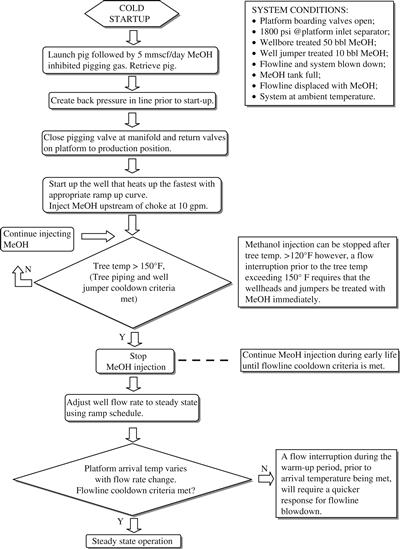
Figure 12-7 Operating Logic Chart of Start-Up for a Cold Well and a Cold Flowline
12.3.1 Well Start-Up and Shut-Down
Figure 12-8 shows a simplified typical tree schematic. The subsea tree’s production wing valve (PWV) is designated as the underwater safety valve (USV). The production master valve (PMV) is manufactured to USV specifications, but will only be designated for use as the USV if necessary. The well has a remotely adjustable subsea choke to control flow. The subsea choke is used to minimize throttling across the subsea valves during start-up and shutdown.
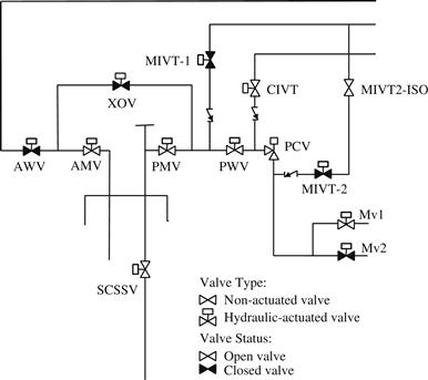
Figure 12-8 Simplified Tree Schematic
12.3.1.1 Well Start-Up
The following start-up philosophies are used for cases in which well start-up poses a risk for flowline blockage, particularly if a hydrate blockage is suspected based on the flow assurance study from the design phase:
• Wells will be started up at a rate that allows minimum warm-up time, while considering drawdown limitations. There will be a minimum flow rate below which thermal losses across the system will keep the fluids in the hydrate-formation region.
• It may not be possible to fully inhibit hydrates at all water cuts, particularly in the wellbore. High water-cut wells will be brought on line without being fully inhibited. Procedures will be developed to minimize the risk of blockage if an unexpected shutdown occurs.
• The system is designed to inject hydrate inhibitor (typically methanol) at the tree during start-up or shutdown. The methanol injected during initial start-up will inhibit the well jumpers, manifold, and flowline if start-up is interrupted and blowdown is not yet possible.
12.3.1.2 Well Shut-down
Well shutdown also poses a significant hydrate risk. The following philosophies may be adopted during shutdown operations:
• The subsea methanol injection system is capable of treating or displacing produced fluids with hydrate inhibitor between the manifold and SCSSV following well shutdown to prevent hydrate formation.
• Hydrate prevention in the flowlines is accomplished by blowing the flowline pressure down to less than the hydrate-formation pressure at ambient seabed temperatures.
• Most well shut-downs will be due to short-duration host facility shut-downs. The subsea trees, jumpers, and flowlines are insulated to slow the cooling process and allow the wells to be restarted without having to initiate a full shutdown operation.
12.3.2 Flowline Blowdown
12.3.2.1 Why Do We Blow Down?
The temperature of a flowline system is kept from forming hydrates by the heat from the reservoir fluids moving through the subsea flowlines during steady-state operation. When well shutdown occurs, and the pressure in the system is still high but the temperature of the system will decrease as heat is transferred to the ambient environment, hydrates may form in the flowline. Once the blowdown of the fluid pressures to below the hydrate-formation pressure corresponding to the environmental temperature has been performed, it is safe—from the hydrate-formation point of the view—to leave the system in this condition indefinitely.
12.3.2.2 When Do We Blow Down?
The blowdown is carried out based on several factors:
When the flowline is shut down, the countdown to the hydrate-formation temperature begins. Several hours of no-touch cooldown time is expended before hydrate inhibitor injection or blowdown is required. The base of the risers is the most at risk for hydrate formation in a subsea tie-back system. Riser bases have the least amount of insulation, lowest temperature fluid at the seafloor, and, once the system is shutdown, fluids in the vertical section condense and flow downhill to pool at the riser base. Therefore, this section of the flowline must be treated early to prevent hydrate formation. The hydrate inhibitor is injected at the platform and this will mix with the fluids at the riser base and will effectively lower the temperature at which gas/water interfaces form hydrates. This will allow us to avoid blowdown for several more hours.
Once a blowdown operation has begun, the topside PLC timer is used to determine the length of time to blow the system down. Following a shutdown, all of the flowlines will need to be completely blown down by the end of 12th hour, which is different depending on the project’s requirement. Following an extended shutdown that resulted in blowdown of the subsea system, the remaining fluids must be removed from the flowlines before the flowlines can be repressurized. The fluids remaining in the flowlines will have water present and the temperature will be the same as the water temperature. When cold, high-pressure gas is introduced to water, hydrates can form. One option is pigging the flowline to remove residual fluids; sometimes displacement with hot oil is performed without pigging. Prior to beginning a pigging operation, ensure that adequate quantities of methanol are on board the platform for start-up operations and subsequent shutdown or aborted start-up.
REFERENCES
1. Hammerschmidt EG. Gas Hydrate Formation in Natural Gas Pipelines. Oil & Gas Journal. 1939;vol. 37 No. 50.
2. Kaczmarski AA, Lorimer SE. Emergence of Flow Assurance as a Technical Discipline Specific to Deepwater: Technical Challenges and Integration into Subsea Systems Engineering. Houston: OTC 13123, Offshore Technology Conference; 2001.
3. Sloan ED. Hydrate Engineering, Monograph 21., Texas: Society of Petroleum Engineers, Richardson; 2000.
4. Pattee FM, Kopp F. Impact of Electrically-Heated Systems on the Operation of Deep Water Subsea Oil Flowlines. Houston: OTC 11894, Offshore Technology Conference; 2000.
5. S.E. Lorimer, B.T. Ellison, Design Guidelines for Subsea Oil Systems, presented at Facilities 2000: Facilities Engineering into the Next Millennium, (2000).