Chapter 15
Hydrates
Contents
15.1. Introduction
15.2. Physics and Phase Behavior
15.2.1. General
15.2.2. Hydrate Formation and Dissociation
15.2.3. Effects of Salt, MeOH, and Gas Composition
15.2.4. Mechanism of Hydrate Inhibition
15.2.4.1. Thermodynamic Inhibitors
15.2.4.2. Low-Dosage Hydrate Inhibitors
15.3. Hydrate Prevention
15.3.1. Thermodynamic Inhibitors
15.3.2. Low-Dosage Hydrate Inhibitors
15.3.3. Low-Pressure Operation
15.3.4. Water Removal
15.3.5. Thermal Insulation
15.3.6. Active Heating
15.3.6.1. Electrical Heating
15.3.6.2. Hot Fluid Circulation Heating in a Pipe Bundle
15.4. Hydrate Remediation
15.4.1. Depressurization
15.4.2. Thermodynamic Inhibitors
15.4.3. Active Heating
15.4.4. Mechanical Methods
15.4.5. Safety Considerations
15.5. Hydrate Control Design Philosophies
15.5.1. Selection of Hydrate Control
15.5.2. Cold Flow Technology
15.5.3. Hydrate Control Design Process
15.5.4. Hydrate Control Design and Operating Guidelines
15.1 Introduction
Natural gas hydrates are crystalline compounds formed by the physical combination of water molecules and certain small molecules in hydrocarbons fluid such as methane, ethane, propane, nitrogen, carbon dioxide, and hydrogen sulfide. Hydrates are easily formed when the hydrocarbon gas contains water at high pressure and relatively low temperature.
As development activities in deeper waters increase, gas hydrates have become one of the top issues in the offshore industry. Deepwater operations are being conducted all over the world in locations such as the Gulf of Mexico (GoM), West Africa (WA), and the North Sea (NS). Gas hydrate problems manifest themselves most commonly during drilling and production processes. Hydrates may appear anywhere and at any time in an offshore system when there is natural gas, water, and suitable temperature and pressure. Figure 15-1 shows a sketch of areas where hydrate blockages may occur in a simplified offshore deepwater system from the well to the platform export flowline. Hydrate blockages in a subsea flowline system are most likely to be found in areas where the direction of flow changes in the well, pipeline, and riser parts of a system.

Figure 15-1 Typical Offshore Well, Production Pipeline and Platform [1]
Hydrates are rarely found in the tubing below the downhole safety valve and the pipelines after the platform. In general, hydrocarbon fluids are at higher pressure and higher temperature before the downhole safety valve, such that the fluid temperature is higher than the hydrate formation temperature corresponding to the local pressure. On the platform, the processes of separation, drying, and compression are usually carried out. First the multiphase hydrocarbons fluids are separated into gas, oil, and water phases; then, the gas is dried and dehydrated; last, the gas is compressed for export. After gas and water are separated on the platform, hydrates cannot form in a gas export flowline without the presence of water.
Figure 15-2 shows typical temperature variations with water depth in the GoM. At the water surface, the temperature deviation in all seasons is about 15°F. When water depth is deeper than 3000 ft, the temperature deviations are very small and water temperature at the seabed becomes approximately constant at 40°F. In the wellhead and Christmas tree, many valves are used to control the production operation. Hydrates may possibly occur during the shutdown/start-up operation in the well and Christmas tree because the ambient temperatures are typically around 40°F in deepwater, even though they may not form during normal operation at steady-state conditions in which the flow rate and temperature of hydrocarbon fluid are higher. In most deepwater production, the ambient water temperature is the main factor causing hydrate formation in the subsea system, but numerous examples also exist of hydrates forming due to Joule-Thomson (JT) cooling of gas, where the gas expands across a valve, both subsea and on the platform. Without insulation or another heat control system for the flowline, the fluids inside a subsea pipeline will cool to the ambient temperature within a few miles from the well. The cooling rate per length depends on the fluid composition, flow rate, ambient temperature, pipe diameter, and other heat transfer factors.

Figure 15-2 Seawater Temperatures of GoM for All Seasons at Different Water Depths [2]
The development of hydrates should be avoided in offshore engineering because they can plug flowlines, valves, and other subsea devices. Hydrates are of importance in deepwater gas developments because ambient temperatures are low enough to be in the hydrate formation region at operating pressures. The presence of a certain amount of water in the hydrocarbon systems can be troublesome due to the formation of hydrates. When temperature and pressure are in the hydrate formation region, hydrates grow as long as water and small molecule hydrocarbons are present. Hydrate crystals can develop into flow blockages, which can be time consuming to clear in subsea equipment or flowlines and cause safety problems. Lost or delayed revenue and costs associated with hydrate blockages can be significant due to vessel intervention costs and delayed production. Thus, hydrate prevention and remediation are important design factors for deepwater developments.
The following topics about hydrates are discussed in this chapter:
15.2 Physics and Phase Behavior
15.2.1 General
Natural gas hydrates are crystalline water structures with low-molecular-weight guest molecules. They are often referred to as clathrate hydrates. The presence of the gas molecules leads to stability of the crystalline structure, allowing hydrates to exist at much higher temperatures than ice. Natural gas hydrates typically form one of three crystal structures, depending primarily on the sizes of the guest molecules. They are metastable minerals whose formation, stability, and decomposition depend on pressure, temperature, composition, and other properties of the gas and water. Hydrate formers include nitrogen, carbon dioxide, hydrogen sulfide, methane, ethane, propane, iso-butane, n-butane, and some branched or cyclic C5–C8 hydrocarbons. Figure 15-3 shows one of the typical hydrate crystal structures found in oil and gas production systems.

Figure 15-3 Hydrate Crystal Structures in Oil and Gas Production Systems [2]
Natural gas hydrates are composed of approximately 85 mol% water; therefore, they have many physical properties similar to those of ice. For instance, the appearance and mechanical properties of hydrates are comparable to those of ice. The densities of hydrates vary somewhat due to the nature of the guest molecule(s) and the formation conditions, but are generally comparable to that of ice. Thus, hydrates typically will float at the water/hydrocarbon interface. However, in some instances, hydrates have been observed to settle on the bottom of the water phase. If a hydrate plug breaks from the pipe walls, it can be pushed down along the flowline by the flowing of hydrocarbon fluid like an ice bullet, potentially rupturing the flowline at a restriction or bend.
Four components are required to form gas hydrates: water, light hydrocarbon gases, low temperature, and high pressure. If any one of these components is absent, then gas hydrates will not form. Hydrate problems can appear during normal production, but transient operations are often more vulnerable. For instance, during a shut-down, the temperature of the subsea line drops to that of the surrounding environment. Given sufficient time under these high pressures and low temperatures, hydrates will form.
The extent to which the gas, oil, and water partition during shutdown somewhat limits the growth of hydrates; although direct contact between the gas phase and the water phase is not needed for hydrate formation, an intervening oil layer slows transport of the hydrate-forming molecules. Additionally, hydrates typically form in a thin layer at the water/oil interface, which impedes further contact between the water and gas molecules. Even if the flowlines do not plug during shutdown, when the well is restarted, the agitation breaks the hydrate layer and allows good mixing of the subcooled water and gas. Rapid hydrate formation often leads to a blockage of flow at low spots where water tends to accumulate. Plugging tendency increases as the water cut increases, because there is a higher likelihood that sufficient hydrate particles will contact each other and stick together. Other typical locations include flow restrictions and flow transitions, as occurs at, for instance, elbows and riser bases.
Hydrate plugs may also occur in black oil subsea systems. Most deepwater black oil systems are not producing significant volumes of water. As water cuts rise, the incidence of hydrate plugs in black oil lines will certainly increase. Some black oils have a tendency not to plug, even when hydrates are formed. The hydrates remain small particles dispersed in the liquid phase and are readily transported through the flowline. These back oils will eventually plug with hydrates if the water cut gets high enough.
15.2.2 Hydrate Formation and Dissociation
Hydrate formation and dissociation curves are used to define pressure/temperature relationships in which hydrates form and dissociate. These curves may be generated by a series of laboratory experiments, or more commonly, are predicted using thermodynamic software such as Multi-Flash or PVTSIM based on the composition of the hydrocarbon and aqueous phases in the system. The hydrate formation curve defines the temperature and pressure envelope in which the entire subsea hydrocarbons system must operate in at steady state and transient conditions in order to avoid the possibility of hydrate formation [3].
Figure 15-4 shows an example of these curves, which shows the stability of natural gas hydrates as a function of pressure and temperature. To the right of the dissociation curve is the region in which hydrates do not form; operating in this region is safe from hydrate blockages. To the left of hydrate formation curve is the region where hydrates are thermodynamically stable and have the potential to form [4]. This does not mean that hydrates will necessarily form or that formed hydrates will cause operational difficulties. The stability of hydrates increases with increasing pressure and decreasing temperature. There is often a delay time or the temperature must be lowered somewhat below the hydrate stability temperature in order for hydrates to form. The subcooling of a system is often used when discussing gas hydrates, which is defined as the difference between hydrate stability temperature and the actual operating temperature at the same pressure. If the system is operating at 40°F and 3000 psi, and the hydrate dissociation temperature is 70°F, then the system is experiencing 30°F of subcooling.
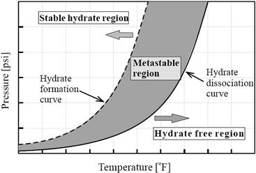
Figure 15-4 Hydrate Formation and Dissociation Regions
The subcooling of a system without hydrate formation leads to an area between the hydrate formation temperature and the hydrate dissociation temperature, called the metastable region, where hydrate is not stable. Some software packages attempt to predict this metastable region. Regularly operation within this metastable region is risky. While such differences in hydrate formation and dissociation temperatures are readily observed in the laboratory, the quantitative magnitude of this hysteresis is apparatus and technique dependent.
Hydrates may not form for hours, days, or even at all even if a hydrocarbon system containing water is at a temperature and pressure conditions close to the hydrate dissociation curve. A certain amount of “subcooling” is required for hydrate formation to occur at rates sufficient to have a practical impact on the system. Figure 15-5 shows the variation of hydrate formation time with the subcooling of hydrate formation temperature. When subcooling increases, the hydrate formation time decreases exponentially. In general, subcooling higher than 5°F will cause hydrate formation to occur at the hydrocarbon/water interface in flowlines.

Figure 15-5 Variation of Hydrate Formation Time with Subcooling [5]
A thermodynamic understanding of hydrates indicates the conditions of temperature, pressure, and composition at which a hydrate may form. However, it does not indicate where or when a hydrate plug will form in the system. Hydrate plugs can form in just a few minutes, or take several days to block production. There are two mechanisms of plug formation, one in which hydrates slowly build up on the bottom of the pipe, gradually restricting flow, and the other in which hydrates agglomerate in the bulk fluid, forming masses of slush that bridge and eventually block the flow. Both mechanisms have been observed in the field, although the latter is believed to be more prevalent. The mechanics of plug formation are not yet well understood, although it is known that certain geometries, such as flow restrictions at chokes, are prone to hydrate plug formation.
Control of hydrates relies on keeping the system conditions out of the region in which hydrates are stable. During oil production operations, temperatures are usually above the hydrate formation temperature, even with the high system pressures at the wellhead (on the order of 5000 to 10,000 psi). However, during a system shutdown, even well-insulated systems will fall to the ambient temperatures eventually, which in the deep GoM is approximately 38 to 40°F. Many methods are available for hydrate formation prediction. Most of them are based on light gas hydrocarbon systems and vary in the complexity of the factors utilized within the computational procedures. The Peng-Robinson method is one typical equation of state (EOS) method that is currently extensively utilized to predict hydrate boundaries.
Knowledge about hydrates has significantly improved in the past 10 years. Hydrate disassociation can be predicted within 1 to 3° with the exception of brines that have a high salt concentration. The hydrate disassociation curves typically provide conservative limits for hydrate management design. The effects of thermodynamic hydrate inhibitors, methanol and ethylene glycols, can be predicted with acceptable accuracy.
When the temperature and pressure are in the hydrate region, hydrates grow as long as water and light hydrocarbons are available and can eventually develop blockages. Clearing hydrate blockages in subsea equipment or flowlines poses safety concerns and can be time consuming and costly. Hydrate formation is typically prevented by several methods including controlling temperature, controlling pressure, removing water, and by shifting thermodynamic equilibrium with chemical inhibitors such as methanol or monoethylene glycol, low-dosage hydrate inhibitors.
15.2.3 Effects of Salt, MeOH, and Gas Composition
The hydrate dissociation curve may be shifted toward lower temperatures by adding a hydrate inhibitor. Methanol, ethanol, glycols, sodium chloride, and calcium chloride are common thermodynamic inhibitors. Hammerschmidt [6] suggested a simple formula to roughly estimate the temperature shift of the hydrate formation curve:
![]() 15-1
15-1
where
![]() : temperature shift, hydrate depression, °C;
: temperature shift, hydrate depression, °C;
K: constant, which is defined in Table 15-1;
Table 15-1. Constant of Equation (15-1) for Various Inhibitors
| Inhibitor | K-Value |
| Methanol | 2335 |
| Ethanol | 2335 |
| Ethylene glycol (MEG) | 2700 |
| Diethylene glycol (DEG) | 4000 |
| Triethylene glycol (TEG) | 5400 |
W: concentration of the inhibitor in weight percent in the aqueous phase;
M: molecular weight of the inhibitor divided by the molecular weight of water.
The Hammerschmidt equation was generated based on more than 100 natural gas hydrate measurements with inhibitor concentrations of 5 to 25 wt% in water. The accuracy of the equation is 5% average error compared with 75 data points. The hydrate inhibition abilities are less for substances with a larger molecular weight of alcohol, for example, the ability of methanol is higher than that of ethanol and glycols. With the same weight percent, methanol has a higher temperature shift than that of glycols, but MEG has a lower volatility than methanol and MEG may be recovered and recycled more easily than methanol on platforms.
Figure 15-6 shows the effect of typical thermodynamic inhibitors on hydrate formation at 20 wt% fraction. Salt, methanol, and glycols act as thermodynamic hydrate inhibitors that shift the hydrate stability curve to the left. Salt has the most dramatic impact on the hydrate stability temperature. On a weight basis, salt is the most effective hydrate inhibitor and so accounting correctly for the produced brine salinity is important in designing a hydrate treatment plan. In offshore fields, MEG found more application than DEG and TEG because MEG has a lower viscosity and has more effect per weight.
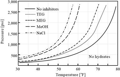
Figure 15-6 Effect of Thermodynamic Inhibitors on Hydrate Formation
Figure 15-7 shows the effect of salts in fluid on hydrate formation. Increasing salt content in the produced brine shifts the hydrate curve to lower temperatures at the same pressure. The solubility of salt to water has a limit based on the temperature.

Figure 15-7 Effect of Salts on Hydrate Formation
Figure 15-8 shows the effect of gas composition on the hydrate formation curve. More small molecular components results in a lower hydrate formation at the same pressure.

Figure 15-8 Effect of Gas Composition on Hydrate Formation
Figure 15-9 shows the effect of weight percentage of methanol on the hydrate formation curve. More weight percentage of methanol leads to a greater temperature shift of the hydrate formation curve.

Figure 15-9 Effect of MeOH on Hydrate Formation
15.2.4 Mechanism of Hydrate Inhibition
Two types of hydrate inhibitors are used in subsea engineering: thermodynamic inhibitors (THIs) and low-dosage hydrate inhibitors (LDHIs).
The most common THIs are methanol and MEG, even though ethanol, other glycols (DEG, TEG), and salts can be effectively used. They inhibit hydrate formation by reducing the temperature at which hydrates form. This effect is the same as adding antifreeze to water to lower the freezing point. Methanol and MEG are the most commonly used inhibitors.
LDHIs include anti-agglomerates and kinetic inhibitors. LDHIs have found many applications in subsea systems in recent years. LDHIs prevent hydrate blockages at significantly lower concentrations, for example, less than 1 wt%, than thermodynamic inhibitors such as methanol and glycols. Unlike thermodynamic inhibitors, LDHIs do not change the hydrate formation temperature. They either interfere with formation of hydrate crystals or agglomeration of crystals into blockages. Anti-agglomerates can provide protection at higher subcooling temperatures than can kinetic hydrate inhibitors. However, low-dosage hydrate inhibitors are not recoverable and they are expensive. The differences in hydrate inhibition mechanism between LDHIs and THIs are shown in Figure 15-10.

Figure 15-10 Mechanism of Hydrate Inhibition
LDHIs are preferred for regular operations because they reduce volumes and can work out to be cheaper. For transient events, the volumes required are not usually that large, so there is not much benefit in LDHIs, and methanol becomes the preferred inhibitor.
15.2.4.1 Thermodynamic Inhibitors
THIs inhibits hydrate formation by reducing the temperature at which hydrates form by changing the chemical potential of water. This effect is the same as adding antifreeze to water to lower the freezing point. THIs includes methanol, glycols, and others. In general, methanol is vaporized into the gas phase of a pipeline, and then dissolves in any free water accumulation to prevent hydrate formation. Hydrate inhibition occurs in the aqueous liquid, rather than in the vapor or oil/condensate. Although most of the methanol dissolves in the water phase, a large amount of methanol remains in the vapor or oil/condensate phase; therefore, the proportions of methanol dissolved in the vapor or oil/condensate liquid phases are usually counted as an economic loss.
15.2.4.2 Low-Dosage Hydrate Inhibitors
Kinetic inhibitors (KIs) are low-molecular-weight water-soluble polymers or copolymers that prevent hydrate blockages by bonding to the hydrate surface and delaying hydrate crystal nucleation and/or growth. They are dissolved in a carrier solvent and injected into the water phase in pipelines [7]. These inhibitors work independently of water cuts, but are limited to relatively low subcooling temperatures (less than 20°F), which may not be sufficient for deepwater applications. For greater subcooling, KIs must be blended with a thermodynamic inhibitor. Additionally, the inhibition effect of KIs is time limited and, thus, their benefit for shut-down is limited. KIs have been applied in the North Sea and the Gulf of Mexico. Long-term shutdowns will require depressurization, which complicates the restart process, and methanol without KIs will be required for restarts. KIs are generally environmentally friendly.
Anti-agglomerates (AAs) are surfactants, which cause the water phase to be suspended as small droplets. When the suspended water droplets convert to hydrates, the flow characteristics are maintained without blockage. They allow hydrate crystals to form but keep the particles small and well dispersed in the hydrocarbon liquid. They inhibit hydrate plugging rather than hydrate formation. AAs can provide relatively high subcooling up to 40°F, which is sufficient for deepwater applications and have completed successful field trials in deepwater GoM production systems. AA effectiveness can be affected by type of oil or condensate, water salinity, and water cut. For deepwater gas developments, AAs can only be applied where there is sufficient condensate, such that the in situ water cut is less than 50%. Methanol may still be required for shutdown and restart. AAs have toxicity issues and may transport microcrystals of hydrate into and remain in the condensed/oil phase.
15.3 Hydrate Prevention
Gas subsea systems typically contain small quantities of water, which allows them to be continuously treated with methanol or glycol to prevent hydrate formation. These inhibitors prevent the formation of hydrates by shifting the hydrate stability curve to lower temperatures for a given pressure. If the systems produce too much water, it is difficult to economically treat with methanol. As a result, the system designs have to incorporate insulation of almost all components of a system and develop complex operating strategies to control hydrate formation during transient activities such as system start-up and shutdown.
Hydrate prevention techniques for subsea systems include [8]:
15.3.1 Thermodynamic Inhibitors
The most common method of hydrate prevention in deepwater developments is injection of thermodynamic inhibitors, which include methanol, glycols, and others. Methanol and MEG are the most commonly used inhibitors, though ethanol, other glycols, and salts can be effectively used.
Inhibitor injection rates, whether methanol or MEG, are a function of water production and inhibitor dosage. Inhibitor dosage is a function of design temperature and pressure and produced fluid composition. Water production multiplied by the methanol dosage is the inhibitor injection rate, which will change throughout field operating life due to typically decreasing operating pressures and increasing water production.
Selection of the hydrate inhibitor is an important decision to be made in the early FEED design and can involve a number of criteria:
• Capital costs of topside process equipment, especially for regeneration;
• Capital costs of subsea equipment;
• Topside weight/area limitations;
• Environmental limits on overboard discharge;
• Contamination of the hydrocarbon fluid and impacts on downstream transport/processing;
Technical advantages and disadvantages of methanol and MEG are compared in Table 15-2.
Table 15-2. Comparison of Methanol and MEG [9]
| Inhibitor | Advantages | Disadvantages |
| Methanol | ||
| MEG |
Methanol and MEG are both effective inhibitors if sufficient quantities are injected; for deep water, inhibitor dosages of 0.7 to 1 bbl of inhibitor per barrel of water are generally used. Methanol can provide higher hydrate temperature depression but this effect is typically countered by high losses to the hydrocarbon liquid and gas phases. The selection of inhibitor is often based on economics, downstream process specifications, environmental issues, and/or operator preferences.
Costs for inhibition systems are driven by up-front capital costs, which are dominated by the regeneration system and also by makeup costs for inhibitor loss. Methanol is cheaper per unit volume, but has greater makeup requirements. Additionally, a methanol regeneration system may be as much as 50% less expensive than a MEG regeneration system. The methanol system starts out cheaper, but, with increasing field life, becomes more expensive due to methanol makeup costs.
The risks of using thermodynamic inhibitors include:
15.3.2 Low-Dosage Hydrate Inhibitors
While development of AAs and KIs continues, cost per unit volume of LDHIs is still relatively high, but is expected to decrease as their use increases. A potentially important advantage is that they may extend field life when water production increases.
15.3.3 Low-Pressure Operation
Low-pressure operation refers to the process of maintaining a system pressure that is lower than the pressure corresponding to the ambient temperature based on the hydrate dissociation curve. For deep water with an ambient temperature of 39°F (4°C), the pressure may need to be 300 psia (20 bar) or less. Operation at such a low pressure in the wellbore is not practical because pressure losses in a deepwater riser or long-distance tie-back would be significant.
By using subsea choking and keeping the production flowline at a lower pressure, the difference between hydrate dissociation and operating temperatures (i.e., subcooling) is reduced. This lower subcooling will decrease the driving force for hydrate formation and can minimize the inhibitor dosage.
15.3.4 Water Removal
If enough water can be removed from the produced fluids, hydrate formation will not occur. Dehydration is a common hydrate prevention technique applied to export pipelines. For subsea production systems, subsea separation systems can reduce water flow in subsea flowlines. The advantage of applying subsea separation is not only hydrate control, but also increasing recovery of reserves and/or accelerating recovery by making the produced fluid stream lighter and easier to lift. Another benefit is reduced topside water handling, treatment, and disposal.
As a new technology, subsea water separation/disposal systems are designed to separate bulk water from the production stream close to subsea trees on the seafloor. Basic components of such a system include a separator, pump to reinject water, and water injection well. Additional components include instrumentation, equipment associated with controlling the pump and separator, power transmission/distribution equipment, and chemical injection. Water cut leaving the separator may be as high as 10%. Operating experience on the Troll Pilot has shown water cuts of 0.5 to 3%. Because these systems do not remove all free water, and water may condense farther downstream, subsea bulk water removal does not provide complete hydrate protection. These systems need to be combined with another hydrate prevention technique, for example, continuous injection of a THI or LDHI. The main risk associated with subsea water separation systems is reliability.
15.3.5 Thermal Insulation
Insulation provides hydrate control by maintaining temperatures above hydrate formation conditions. Insulation also extends the cooldown time before reaching hydrate formation temperatures. The cooldown time gives operators time either to recover from the shutdown and restart a warm system or prepare the system for a long-term shutdown.
Insulation is generally not applied to gas production systems, because the production fluid has low thermal mass and also will experience JT cooling. For gas systems, insulation is only applicable for high reservoir temperatures and/or short tie-back lengths. One advantage of an insulated production system is that it can allow higher water production, which would not be economical with continuous inhibitor injection. However, shutdown and restart operations would be more complicated. For example, long-term shutdowns will probably require depressurization. An overview of insulation requirements was described in the Chapter 14.
15.3.6 Active Heating
Active heating includes electrical heating and hot fluid circulation heating in a bundle. In flowlines and risers, active heating must be applied with thermal insulation to minimize power requirements.
15.3.6.1 Electrical Heating
Electrical heating (EH) is a very fast developing technology and has found applications in the offshore fields including Nakika, Serrano, Oregano, and Habanero in the GoM, and Asgard, Huldra, and Sliepner in the North Sea [10]. Advantages of electrical heating include eliminating flowline depressurization, simplifying restart operations, and providing the ability to quickly remediate hydrate blockages.
Electrical heating techniques include:
15.3.6.2 Hot Fluid Circulation Heating in a Pipe Bundle
Hot fluid heating has many of the same advantages as electrical heating. Instead of using electricity for supplying heat, however, hot fluid, typically inhibited water, circulates in the bundles to provide heat to the production fluids. Examples of such bundles include Statoil Asgard and Gullfaks South, Conoco Britannia, and BP King. These bundles can be complex in design, with thermal and mechanical design, fabrication, installation, life cycle, and risk issues that need to be addressed.
Active heating techniques provide a good level of protection. With active heating, hydrate control is simply a matter of power, insulation, and time. Active heating can increase the operating flexibility of a subsea production system, such that concerns including water cut, start-up, and operating flow rate and depressurization times are of lesser importance.
Electrically heated flowlines and low-dosage hydrate inhibitors are two developing technologies in hydrate prevention for reducing the complexity of the design and operation of subsea systems. Electrically heated flowline technology reduces hydrate concerns in subsea systems. Instead of relying on the lengthy process of blowdown for hydrate remediation, electrical heating provides a much faster way to heat the flowline and remove the plug. The other potential advantages of electrical heating are covered in Chapter 14. Low-dosage hydrate inhibitors reduce the volume of chemicals that must be transported and injected into the subsea system. Methanol treatment rates, for hydrate control, are on the order of one barrel of methanol for each barrel of produced brine. The low-dosage hydrate inhibitors may be able to accomplish the same task at dosage rates of less than 1%. This leads to a reduction in umbilical size and complexity. Note, however, that the hydrate inhibitors must be injected continuously to prevent hydrate formation.
15.4 Hydrate Remediation
Like the kinetics of hydrate formation, hydrate dissociation is a poorly understood subject and applying laboratory observations to field predictions has proven difficult. Part of the reason is the complicated interplay of flow, heat transfer, and phase equilibria. The dissociation behavior of hydrate depends on the hydrate size, porosity, permeability, volume of occluded water, “age” of the deposit, and local conditions such as temperature, pressure, fluids in contact with the plug, and insulation layers over the pipeline.
Two factors combine to make hydrate plugs exceedingly difficult to remove: It takes a large amount of energy to dissociate the hydrate, and heat transfer through the hydrate phase is slow. Hydrates also concentrate natural gas: 1 ft3 of hydrates can contain up to 182 ft3 of gas. This has significant implications for safety in depressurizing hydrate plugs. Hydrate dissociation is highly endothermic. If heat transfer through the pipeline insulation layer from the surroundings is low, the temperature near a dissociating hydrate can drop rapidly. In addition, as gas evolves during hydrate dissociation, JT cooling of the expanding gas is also possible. By either of these mechanisms, additional hydrates and/or ice can form during the dissociation process. For a more complete discussion of gas hydrate structures and properties, the reader is referred to the book by Sloan [1].
Although the design of a unit is intended to prevent hydrate blockages, industry operators must include design and operational provisions for remediation of hydrate blockages. A hydrate blockage remediation plan should be developed for a subsea system where hydrate formation is an issue. This tells operators how to spot when a blockage might be occurring and what to do about it. The state of the art would be to have an “online” or “real-time” system using a calculation engine such as OLGA to continuously predict temperatures and pressures in the pipeline and raise an alarm if hydrate formation conditions are detected. Such a system may also be able to pinpoint the most likely blockage location.
Hydrate remediation techniques are similar to hydrate prevention techniques, which include:
• Depressurization from two sides or one side, by reducing pressure below the hydrate formation pressure at ambient temperature, will cause the hydrate to become thermodynamically unstable.
• Thermodynamic inhibitors can essentially melt blockages with direct hydrate contact.
• Active heating is used to increase the temperature to above the hydrate dissociation temperature and provide significant heat flow to relatively quickly dissociate a blockage.
• Mechanical methods such as drilling, pigging, and scraping have been attempted, but are generally not recommended. Methods include inserting a thruster or pig from a surface vessel with coiled tubing through a workover riser at launchers, and melting by jetting with MEG.
15.4.1 Depressurization
Depressurization is the most common technique used to remediate hydrate blockages in production systems. Rapid depressurization should be avoided because it can result in JT cooling, which can worsen the hydrate problem and form ice. From both safety and technical standpoints, the preferred method to for dissociating hydrates is to depressurize from both sides of the blockage. If only one side of a blockage is depressurized, then a large pressure differential will result across the plug, which can potentially create a high-speed projectile.
When pressure surrounding a hydrate is reduced below the dissociation pressure, the hydrate surface temperature will cool below the seabed temperature, and heat influx from the surrounding ocean will slowly melt the hydrate at the pipe boundary. Lowering the pressure also decreases the hydrate formation temperature and helps prevent more hydrates from forming in the rest of the line. Because most gas flowlines are not insulated, hydrate dissociation can be relatively fast due to higher heat flux from pipeline surfaces, as compared to an insulated or buried flowline.
The depressurization of the flowlines, a process known as blowdown, creates many operational headaches. Not only does the host facility have to handle large quantities of gas and liquid exiting the flowlines, it must also be prepared to patiently wait until the plug dissociates. Because multiple plugs are common, the process can be extremely long and much revenue is lost. Some subsea system configurations, such as flowlines with a number of low spots, can be extremely difficult to blow down. The best policy is to operate, if at all possible, in a manner that prevents hydrates from forming in the first place. Depressurization may not be effective due to production system geometry; a sufficiently high liquid head in the riser or flowline may prevent depressurization below hydrate conditions. In this case, some methods may be needed to reduce the liquid head. If additional equipment is needed to perform depressurization or remediation, equipment mobilization needs to be factored into the total downtime. System designers need to evaluate the cost/benefit of including equipment in the design for more efficient remediation versus using higher remediation times.
15.4.2 Thermodynamic Inhibitors
Thermodynamic inhibitors can be used to melt hydrate blockages. The difficulty of applying inhibitors lies in getting the inhibitor in contact with the blockage. If the injection point is located relatively close to the blockage, as may be the case in a tree or manifold, then simply injecting the inhibitor can be effective. Injecting inhibitor may not always help with dissociating a hydrate blockage, but it may prevent other hydrate blockages from occurring during remediation and restart.
If the blockage can be accessed with coiled tubing, then methanol can be pumped down the coiled tubing to the blockage. In field applications, coiled tubing has reached as far as 14,800 ft in remediation operations, and industry is currently targeting lengths of 10 miles.
15.4.3 Active Heating
Active heating can be used to remediate hydrate plugs by increasing the temperature and heat flow to the blockage; however, safety concerns arise when applying heat to a hydrate blockage. During the dissociation process, gas will be released from the plug. If the gas is trapped within the plug, then the pressure can build and potentially rupture the flowline. Heat evenly applied to a flowline can provide safe, effective remediation.
Active heating can remediate a blockage within hours, whereas depressurization can take days or weeks. The ability to quickly remediate hydrate blockages can enable less conservative designs for hydrate prevention.
15.4.4 Mechanical Methods
Pigging is not recommended for removing a hydrate plug because the plug can become compressed, which will compound the problem. If the blockage is complete, it will not be possible to drive a pig through. For a partial blockage, pigging may create a more severe blockage.
Coiled tubing is another option for mechanical hydrate removal. Drilling a plug is not recommended because it can cause large releases of gas from the blockage. Coiled tubing can be inserted through a lubricator. Coiled tubing access, either at the host or somewhere in the subsea system, should be decided early in the design phase.
15.4.5 Safety Considerations
Knowledge of the location and length of a hydrate blockage is very important in determining the best approach to remediation, although the methodology is not well defined, This information facilitates both safety considerations in terms of distance from the platform and time necessary to dissociate the blockage.
When dissociating a hydrate blockage, operators should assume that multiple plugs may exist both from safety and technical standpoints. The following two important safety issues should be kept in mind:
• Single-sided depressurization can potentially launch a plug like a high-speed projectile and result in ruptured flowlines, damaged equipment, release of hydrocarbons to the environment, and/or risk to personnel.
• Actively heating a hydrate blockage needs to be done such that any gas released from the hydrate is not trapped.
15.5 Hydrate Control Design Philosophies
Steady-state temperature calculations from the flow assurance process are used to indicate the flow rates and insulation systems that are needed to keep the system above the hydrate formation temperature during normal operation. Transient temperature calculations are used to examine the conditions of transient action such as start-up and shutdown process. It is essential for each part of the system to have adequate cooldown time. Dosing of hydrate inhibitor is the way hydrate formation is controlled when system temperatures drop into the range in which hydrates are stable during the transient actions. Dosing calculations of thermodynamic hydrate inhibitor indicate how much inhibitor must be added to the produced water at a given system pressure. The inhibitor dosing requirements are used to determine the requirements for inhibitor storage, pumping capacities, and number of umbilical lines in order to ensure that the inhibitor can be delivered at the required rates for treating each subsea device during start-up and shut-down operations.
15.5.1 Selection of Hydrate Control
Injection rates of thermodynamic inhibitors are a function of water production and inhibitor dosage. Inhibitor dosage is a function of design temperature and pressure, and produced fluid composition. Water production multiplied by the methanol dosage is the inhibitor injection rate, which will change throughout field operating life due to typically decreasing operating pressures and increasing water production. Hydrate control strategies for gas and oil systems are different. Gas systems are designed for continuous injection of a hydrate inhibitor. Water production is small, typically only the water of condensation. Inhibitor requirements are thus relatively small, of the order of 1 to 2 bbl MeOH/mmscf. Oil systems produce free water. Continuous inhibition is generally too expensive so some alternative control system is adopted. Insulation is often used to control hydrates during normal production, and some combination of blowdown and methanol injection is used during start-up and shutdown. But insulation is costly, and the more serious drawback may be lengthening of the hydrate plug remediation time, because insulation limits the heat transfer required to melt the hydrate solid, for cases in which hydrates have formed.
Table 15-3 provides a summary of the applications, benefits, and limitations of the three classes of chemical inhibitors.
Table 15-3. Summary of Chemical Inhibitors Applications, Benefits, and Limitations [11]
| Thermodynamic Hydrate Inhibitors | Kinetic Hydrate Inhibitors | Anti-Agglomerate Inhibitors |
| Applications | ||
| Benefits | ||
| Limitations | ||
Figure 15-11 shows the relationship between hydrate control options for different water cuts and pipeline lengths. LDHIs offer the ability to treat production with higher water rates because they are injected at lower quantities. Subsea separation of bulk water in combination with either thermodynamic or low-dosage inhibitors also can enable developments with potentially high water production. Basically, THIs, LDHIs, low-pressure operation, subsea processing (water separation), and thermal management are used in fields for hydrate prevention in subsea systems.

Figure 15-11 Hydrate Control Method for Different Water Cut and Pipeline Length
The selection of hydrate mitigation and remediation strategies is based on technical and economic considerations and the decision is not always clear-cut. While continuous injection of THIs is expected to remain the most economic and technically feasible approach to hydrate control, LDHIs or subsea processing will offer advantages for some developments. Whatever the hydrate control strategy, these decisions are critical in the early design stage because of the many impacts on both the subsea and topside equipment selection and design.
The main benefits of the thermodynamic hydrate inhibitors are their effectiveness, reliability (provided sufficient quantities are injected), and proven track records. However, these benefits are outweighed by significant limitations, including the high volumes, high associated costs (both CAPEX and OPEX), and their toxicity and flammability. In addition, they are harmful to the environment and significant disposal into the environment is prohibited.
Kinetic hydrate inhibitors are injected in much smaller quantities compared to thermodynamic inhibitors and therefore offer significant potential costs savings, depending on the pricing policies of major chemical suppliers. They are also typically nontoxic and environmentally friendly. Moreover, considerable field experience is now available following a number of successful trials. However, they have some important limitations, including restrictions on the degree of subcooling (typically only guaranteed for less than 10°C) and problems associated with residence times, which as implications for shutdowns. In addition, the effectiveness of KHIs appears to be system specific, meaning that testing programs are required prior to implementation. Unfortunately adequate testing can require appreciable quantities of production fluids, which may not be available, particularly for new field developments. Furthermore, KHIs can interact with other chemical inhibitors (e.g., corrosion inhibitors), and testing programs need to account for this too. Finally, there are no established models for predicting the effectiveness of KHIs, which presents difficulties for field developers considering the application of these chemicals.
The benefits and limitations of anti-agglomerates are largely similar to those for KHIs, although AAs do not have the same subcooling limitations. However, there is uncertainty about the effectiveness of AAs under shutdown or low flow rate conditions and it is postulated that agglomeration may still proceed. In addition, the one major limitation of AAs compared to KHIs or THIs is that they are limited to lower water cuts due the requirement for a continuous hydrocarbon liquid phase. Finally, compared to both THIs and KHIs, field experience with AAs appears to be lacking, which is reflected by the relatively small number of publications available in the open literature.
Thermal management can assist with maintaining some room for response by assisting with adequate temperatures for both hydrate and paraffin control. Passive thermal management is by insulation or burial. Pipe-in-pipe and bundled systems can extend the production cooldown time before continuous hydrate inhibition is required. However, there may not be sufficient thermal capacity to provide the necessary cooldown time for a shutdown greater than 4 to 8 hours. Phase change material insulation systems that provide heat “storage” are beginning to appear as commercial systems. Burial can provide extended cooldown times due to the thermal mass of the soil. Warm-up and cooldown times can be optimized with insulation and thermal mass.
Both electrical and heating media systems belong to the active thermal management process. Heating media systems require pipe-in-pipe or bundle flowline designs to provide the flow area required for the circulation of the heating media. When design, installation, and corrosion management issues are successful, the heating media systems can be reliable. However, the heat transported is still limited by the carrier insulation and heat input at the platform.
15.5.2 Cold Flow Technology
Cold flow technology is a completely new concept that is designed to solve hydrate blockage problems during steady-state operating conditions. It has been recently developed and is owned by SINTEF. It is different from the chemical-based technologies (THIs, LDHIs) and insulation/heating technologies for hydrate protection, and concerns the cost-effective flow of oil, gas, and water mixtures in deepwater production pipelines, from wellhead to processing facility without using chemicals to prevent hydrate or wax deposition. In cold flow technology the hydrate formation occurs under controlled conditions in specialized equipment. The formed hydrate particles flow easily with the bulk fluid mixture as slurry and do not form wall deposits or pipeline blockage. Cold flow technology is environmentally friendly because of the envisaged reduction in the use of bulk and specialty chemicals. This technology provides an exciting challenge and could result in significant economic savings.
Figure 15-12 shows a flow diagram for the cold flow hydrate technology process. The flow enters from a wellbore (WELL), and leaves through a cold flow pipeline (CFP). This system has several main process units: a wellhead unit (WHU), a separator unit (SU), a heat exchanger unit (HXU), and a reactor unit (RU). The term G/L refers to gas/liquid. Depending on the water cut and gas/oil ratio (GOR) and other fluid properties, more than one set of SU+HXU+RU may be required.

Figure 15-12 Block Diagram of Cold Flow Hydrate Technology Process [12]
Figure 15-13 is a schematic of the SINTEF-BP cold flow project, which develops a very robust process for long-distance transportation of an unprocessed well stream containing water by converting the water to a very stable and transportable gas hydrate. This process has been successfully proven in a 1-in. flow loop facility, operated with a variety of field fluids. This technology can reduce CAPEX by 15 to 30% for subsea tie-backs.

Figure 15-13 Schematic of a Cold Flow Project [13]
15.5.3 Hydrate Control Design Process
The hydrate control design process in subsea hydrocarbons system is summarized as follows:
• Determine operating conditions: pressure, temperature, GOR, water cut.
• Obtain good representative samples of oil, gas, and water.
• Measure chemical composition and phase behavior.
• Analyze reservoir fluids to determine hydrate formation conditions.
• Perform hydrate prediction calculations.
• Estimate the effects of insulation and thermodynamic inhibitors.
• Determine thermodynamic hydrate inhibitor dosing and sizes of umbilical and inhibitor storage; consider the use of LDHIs.
15.5.4 Hydrate Control Design and Operating Guidelines
The guidelines utilized for hydrate control in subsea hydrocarbon system designs and operations are summarized as follows:
• Keep the entire production system out of the hydrate formation envelope during all operations. Current knowledge is not sufficient to design a system that can operate in the hydrate region without hydrate or blockage formation.
• Inject thermodynamic inhibitors at the subsea tree to prevent the formation of hydrates in the choke and downstream during transient operations.
• Use LDHIs only for transient start-up/shutdown operations and not for continuous operation.
• Insulate flowlines and risers from heat loss during normal operation and to provide cooldown time during shutdown. Insulation of subsea equipment (trees, jumpers, and manifolds) should also be done.
• Consider wellbore insulation to provide fast warm-up during restart operations and to increase operating temperatures during low flow rate operation.
• Determine minimum production rates and flowing wellhead temperatures and check consistency with technical and economic criteria.
• Establish well and flowline start-up rates to minimize inhibitor injection while assuring that the system warms in an acceptable amount of time.
• Ramp-up well production rates sufficiently fast to outrun hydrate blockage formation in wellbores.
• Provide system design and operating strategies to ensure the system can be safely shut down.
• Monitor water production from individual wells.
• Locate SCSSVs at a depth where the geothermal temperature is higher than the hydrate temperature at shut-down pressure.
• Remediate hydrate blockages via depressurization or heating.
15.6 Recovery of Thermodynamic Hydrate Inhibitors
Thermodynamic hydrate inhibitors (methanol, glycols) are widely used as a primary hydrate inhibitor in subsea systems. For projects producing oil, the amount of methanol is limited in terms of the oil’s quality. The issue of an oxygenated solvent limit for glycols in oil is still under discussion. Even though the recovery units of methanol and glycol are improving, the units require appreciable heat to recover the THIs, and scaling in the methanol and glycol stills can generate operations challenges, especially when the produced water chemistry is not available from the reservoir appraisal during the design phase. Glycol recovery units can be designed to remove the salts that have traditionally limited the glycol quality. To reduce the methanol and glycol to the requirements of oil quality, crude washing requires large volumes of water that must be treated to seawater injection quality. The recovery units and wash units have a significant weight and can affect the project’s design. These units are large and heavy.
Figure 15-14 shows a typical flowchart for an offshore gas production facility with methanol as the hydrate inhibitor. As shown in the figure, the fluids from the subsea flowlines enter the separation vessels and are then distributed in three separate phases:
• Gas export stream to onshore gas plant in vapor phase;
• Condensate or oil export stream to shore in liquid hydrocarbon phase;

Figure 15-14 MeOH Recovery Flowchart of Offshore Gas Facility
The methanol in the hydrocarbon vapor phase is recovered by adsorption, and the methanol in the hydrocarbon liquid phase is recovered by water wash, mechanical separation, or a combination of the two. Most of the injected methanol is in the aqueous phase. A methanol tower is used to recover the methanol from the aqueous phase. More than 96% of the methanol injected can be recovered if good engineering judgment and experience are applied.
The aqueous phase mixture contains most of the methanol injected to the system. Methanol is a highly polar liquid and is fully miscible with water; therefore, the recovery of methanol from water is achieved by distillation rather than phase separation.
Methanol is fully miscible with water, while the solubility of methanol in hydrocarbons is very small. Therefore, water (the solvent) can be used to extract methanol (the solute) from the hydrocarbon condensate (the feed) efficiently. Because water is the solvent, this extraction process is called water wash.
Methanol losses in the hydrocarbon liquid phase are difficult to predict. Solubility of methanol is a strong function of both the water phase and hydrocarbon phase compositions. The recovery of the dispersed and dissolved methanol from the feed to the condensate stabilizer can be achieved by mechanical separation via coalescence, liquid–liquid extraction, or a combination of the two depending on the feed characteristics, weight, space, and cost of the entire subsea topside operation. Mechanical separation can separate the dispersed methanol from the hydrocarbon liquid phase to a certain extent. Liquid–liquid extraction can recover the smaller droplets of dispersed methanol and the dissolved methanol from the hydrocarbon liquid phase. However, liquid–liquid extraction is more costly than mechanical separation. The solvent needs to be regenerated and reused by the extraction tower. It increases the flow rate and the heating and cooling duties of the methanol distillation tower. For subsea operation, the treating facility’s space requirements, weight, and cost have to be considered together to determine which system to use to recover the methanol from the liquid hydrocarbon phase.
Methanol in the hydrocarbon vapor phase can be recovered by adsorption. If the hydrocarbon vapor passes through a cryogenic system, the methanol in the hydrocarbon vapor phase condenses into the liquid phase and can be recovered.
REFERENCES
1. Sloan E. Offshore Hydrate Engineering Handbook. SPE Monograph. 2000;vol. 21.
2. Lorimer SE, Ellison BT. Design Guidelines for Subsea Oil Systems. Facilities 2000: Facilities Engineering into the Next Millennium 2000.
3. Ellison BT, Gallagher CT, Lorimer SE. The Physical Chemistry of Wax, Hydrates, and Asphaltene. OTC. 2000;11963.
4. B. Edmonds, R.A.S. Moorwood, R. Szczepanski, X. Zhang, Latest Developments in Integrated Prediction Modeling Hydrates, Waxes and Asphaltenes, Focus on Controlling Hydrates, Waxes and Asphaltenes, IBC, Aberdeen, 1999, October.
5. Ellision B, Gallagher CT. Baker Petrolite Flow Assurance Course. Houston: Texas; 2001.
6. Hammerschmidt EG. Possible Technical Control of Hydrate Formation in Natural Gas Pipelines. Brennstoff-Chemie. 1969;vol. 50:117–123.
7. Mehta AP, Hebert PB, Cadena ER, Weatherman JP. Fulfilling the Promise of Low Dosage Hydrate Inhibitors: Journey from Academic Curiosity to Successful Field Implementation. OTC. 2002;14057.
8. Cochran S, Hydrate Control, Remediation Best. Practices in Deepwater Oil Developments. OTC. 2003;15255.
9. Cochran S, Gudimetla R. Hydrate Management: Its Importance to Deepwater Gas Development Success. World Oil. 2004;vol. 225:55–61.
10. Pattee FM, Kopp F. Impact of Electrically-Heated Systems on the Operation of Deep Water Subsea Oil Flowlines. Houston, Texas: OTC11894, Offshore Technology Conference; 2000; May.
11. Pickering PF, Edmonds B, Moorwood RAS, Szczepanski R, Watson MJ. Evaluating New Chemicals and Alternatives for Mitigating Hydrates in Oil & Gas Production. Aberdeen, Scotland: IIR Conference; 2001.
12. Gudmundsson JS. Cold Flow Hydrate Technology, 4th International Conference on Gas Hydrates. Yokohama, Japan 2002; May.
13. Lysne D. Ultra Long Tie-Backs in Arctic Environments with the SINTEF-BP Cold Flow Concept, Oil and Gas Developments in Arctic and Cold Regions. Houston, Texas: U.S.–Norway Oil & Gas Industry Summit; 2005; March.