Chapter 17
Subsea Corrosion and Scale
Contents
17.1. Introduction
17.2. Pipeline Internal Corrosion
17.2.1. Sweet Corrosion: Carbon Dioxide
17.2.1.1. Corrosion Predictions
17.2.1.2. Comparison of CO2 Corrosion Models
17.2.1.3. Sensitivity Analysis for CO2 Corrosion Calculation
17.2.2. Sour Corrosion: Hydrogen Sulfide
17.2.3. Internal Coatings
17.2.4. Internal Corrosion Inhibitors
17.3. Pipeline External Corrosion
17.3.1. Fundamentals of Cathodic Protection
17.3.2. External Coatings
17.3.3. Cathodic Protection
17.3.3.1. Design Life
17.3.3.2. Current Density
17.3.3.3. Coating Breakdown Factor
17.3.3.4. Anode Material Performance
17.3.3.5. Resistivity
17.3.3.6. Anode Utilization Factor
17.3.4. Galvanic Anode System Design
17.3.4.1. Selection of Anode Type
17.3.4.2. CP Design Practice
17.3.4.3. Anode Spacing Determination
17.3.4.4. Commonly Used Galvanic Anodes
17.3.4.5. Pipeline CP System Retrofit
17.4. Scales
17.4.1. Oil Field Scales
17.4.1.1. Calcium Carbonate
17.4.1.2. Calcium Sulfate
17.4.1.3. Barium Sulfate
17.4.1.4. Strontium Sulfate
17.4.2. Operational Problems Due to Scales
17.4.2.1. Drilling/Completing Wells
17.4.2.2. Water Injection
17.4.2.3. Water Production
17.4.2.4. HP/HT Reservoirs
17.4.3. Scale Management Options
17.4.4. Scale Inhibitors
17.4.4.1. Types of Scale Inhibitors
17.4.4.2. Scale Inhibitor Selection
17.4.5. Scale Control in Subsea Field
17.1 Introduction
In most subsea developments, oil and gas products are transported from subsea wells to platforms in multiphase flow without using a separation process. Corrosion, scale formation, and salt accumulation represent increasing challenges for the operation of subsea multiphase pipelines. Corrosion can be defined as a deterioration of a metal, due to chemical or electrochemical interactions between the metal and its environment. The tendency of a metal to corrode depends on a given environment and the metal type.
The unprotected buried or unburied pipelines that are exposed to the atmosphere or submerged in water are susceptible to corrosion in external pipe surfaces, and without proper maintenance, the pipeline will eventually corrode and fail, because corrosion can weaken the structure of the pipeline, making it unsafe for transporting oil, gas, and other fluids. A strong adhesive external coating over the whole length of the pipeline will tend to prevent corrosion. However, there is always the possibility of coating damage during handling of the coated pipe either during shipping or installation. Cathodic protection is provided by sacrificial anodes to prevent the damaged areas from corroding.
The presence of carbon dioxide (CO2), hydrogen sulfide (H2S), and free water in the internal production fluid can cause severe corrosion problems in oil and gas pipelines. Internal corrosion in wells and pipelines is influenced by temperature, CO2 and H2S content, water chemistry, flow velocity, oil or water wetting, and the composition and surface condition of the steel. Corrosion-resistant alloys such as 13% Cr steel and duplex stainless steel are often used in the downhole piping of subsea structures. However, for long-distance pipelines, carbon steel is the only economically feasible alternative and corrosion has to be controlled so as to protect the flowline both internally and externally.
Scale is a deposit of the inorganic mineral components of water. Solids may precipitate and deposit from the brine once the solubility limit or capacity is exceeded. The solid precipitates may either stay in suspension in the water or form an adherent scale on a surface such as a pipe wall. Suspended scale solids may cause problems such as formation plugging. Adherent scale deposits can restrict flow in pipes and damage equipment such as pumps and valves. Corrosion and microbiological activity are often accelerated under scale deposits.
The purpose of this chapter is to evaluate the effects of corrosion and scale deposits on subsea oil and gas pipelines and describe protection methods. The evaluation focuses on the following three aspects:
17.2 Pipeline Internal Corrosion
Two types of corrosion can occur in oil and gas pipeline systems when CO2 and H2S are present in the hydrocarbon fluid: sweet corrosion and sour corrosion. Sweet corrosion occurs in systems containing only carbon dioxide or a trace of hydrogen sulfide (H2S partial pressure < 0.05 psi). Sour corrosion occurs in systems containing hydrogen sulfide above a partial pressure of 0.05 psia and carbon dioxide.
When corrosion products are not deposited on the steel surface, very high corrosion rates of several millimeters per year can occur. This “worst case” corrosion is the easiest type to study and reproduce in the laboratory. When CO2 dominates the corrosivity, the corrosion rate can be reduced substantially under conditions where iron carbonate can precipitate on the steel surface and form a dense and protective corrosion product film. This occurs more easily at high temperatures or high pH values in the water phase. When H2S is present in addition to CO2, iron sulfide films are formed rather than iron carbonate, and protective films can be formed at lower temperature, since iron sulfide precipitates much easier than iron carbonate. Localized corrosion with very high corrosion rates can occur when the corrosion product film does not give sufficient protection, and this is the most feared type of corrosion attack in oil and gas pipelines.
17.2.1 Sweet Corrosion: Carbon Dioxide
CO2 is composed of one atom of carbon with two atoms of oxygen. It is a corrosive compound found in natural gas, crude oil, and condensate and produced water. It is one of the most common environments in the oil field industry where corrosion occurs. CO2 corrosion is enhanced in the presence of both oxygen and organic acids, which can act to dissolve iron carbonate scale and prevent further scaling.
Carbon dioxide is a weak acidic gas and becomes corrosive when dissolved in water. However, CO2 must hydrate to carbonic acid H2CO3, which is a relatively slow process, before it becomes acidic. Carbonic acid causes a reduction in the pH of water and results in corrosion when it comes in contact with steel.
Areas where CO2 corrosion is most common include flowing wells, gas condensate wells, areas where water condenses, tanks filled with CO2, saturated produced water, and pipelines, which are generally corroded at a slower rate because of lower temperatures and pressures. CO2 corrosion is enhanced in the presence of both oxygen and organic acids, which can act to dissolve iron carbonate scale and prevent further scaling.
The maximum concentration of dissolved CO2 in water is 800 ppm. When CO2 is present, the most common forms of corrosion include uniform corrosion, pitting corrosion, wormhole attack, galvanic ringworm corrosion, heat-affected corrosion, mesa attack, raindrop corrosion, erosion corrosion, and corrosion fatigue. The presence of carbon dioxide usually means no H2 embrittlement.
CO2 corrosion rates are greater than the effect of carbonic acid alone. Corrosion rates in a CO2 system can reach very high levels (thousands of mils per year), but it can be effectively inhibited. Velocity effects are very important in the CO2 system; turbulence is often a critical factor in pushing a sweet system into a corrosive regime. This is because it either prevents formation or removes a protective iron carbonate (siderite) scale.
CO2 corrosion products include iron carbonate (siderite, FeCO3), iron oxide, and magnetite. Corrosion product colors may be green, tan, or brown to black. This can be protective under certain conditions. Scale itself can be soluble. Conditions favoring the formation of a protective scale are elevated temperatures, increased pH as occurs in bicarbonate-bearing waters, and lack of turbulence, so that the scale film is left in place. Turbulence is often the critical factor in the production or retention of a protective iron carbonate film. Iron carbonate is not conductive. Therefore, galvanic corrosion cannot occur. Thus, corrosion occurs where the protective iron carbonate film is not present and is fairly uniform over the exposed metal. Crevice and pitting corrosion occur when carbonate acid is formed. Carbon dioxide can also cause embrittlement, resulting in stress corrosion cracking.
17.2.1.1 Corrosion Predictions
CO2 corrosion of carbon steel used in oil production and transportation, when liquid water is present, is influenced by a large number of parameters, some of which are listed below:
• Flow (flow regime and velocity);
• Concentration of dissolved corrosion product (FeCO3);
• Concentration of acetic acid;
The detailed influence of these parameters is still poorly understood and some of them are closely linked to each other. A small change in one of them may influence the corrosion rate considerably.
Various prediction models have been developed and are used by different companies. Among them are the de Waard et al. model (Shell), CORMED (Elf Aquitaine), LIPUCOR (Total), and a new electrochemically based model developed at IFE. Due to the complexity of the various corrosion controlling mechanisms involved and a built-in conservatism, the corrosion models often overpredict the corrosion rate of carbon steel.
The Shell model for CO2 corrosion is most commonly used in the oil/gas industry. The model is mainly based on the de Waard equation [1] published in 1991. Starting from a “worst case” corrosion rate prediction, the model applies correction factors to quantify the influence of environmental parameters and corrosion product scale formed under various conditions. However, the first version of the model was published in 1975, and it has been revised several times, in order to make it less conservative by including new knowledge and information. The original formula of de Waard and Milliams [1] implied certain assumptions that necessitated the application of correction factors for the influence of environmental parameters and for the corrosion product scale formed under various conditions.
CO2 corrosion rates in pipelines made of carbon steel may be evaluated using industry accepted equations that preferably combine contributions from flow-independent kinetics of the corrosion reaction at the metal surface, with the contribution from the flow-dependent mass transfer of dissolved CO2.
The corrosion rate calculated from the original formula with its correction factors is independent of the liquid velocity. To account for the effect of flow, a new model was proposed that takes the effect of mass transport and fluid velocity into account by means of a so-called resistance model:
![]() (17-1)
(17-1)
where Vcr is the corrosion rate in mm/year, Vr is the flow-independent contribution, denoted as the reaction rate, and Vm is the flow-dependent contribution, denoted as the mass transfer rate.
In multiphase turbulent pipeline flow, Vm depends on the velocity and the thickness of the liquid film, whereas Vr depends on the temperature, CO2 pressure, and pH. For example, for pipeline steel containing 0.18% C and 0.08% Cr, the equations for Vr and Vm for liquid flow in a pipeline are:
![]() (17-2)
(17-2)
where Tmp is the pipeline fluid temperature in °C, and the partial pressure pCO2 of CO2 in bar. The partial pressure pCO2 can be found by:
![]() (17-3)
(17-3)
where nCO2 is the fraction of CO2 in the gas phase, and popr is the operating pressure in bar.
The mass transfer rate Vm is approximated by:
![]() (17-4)
(17-4)
where U is the liquid flow velocity in m/s and d is the inner diameter in meters.
17.2.1.2 Comparison of CO2 Corrosion Models
The corrosion caused by the presence of CO2 represents the greatest risk to the integrity of carbon steel equipment in a production environment and is more common than damage related to fatigue, erosion, or stress corrosion cracking. NORSOK, Shell, and other companies and organizations have developed models to predict the corrosion degradation.
NORSOK’s standard M-506 [2] can be used to calculate the CO2 corrosion rate, which is an empirical model for carbon steel in water containing CO2 at different temperatures, pH, CO2 fugacity and wall shear stress. The NORSOK model covers only the corrosion rate calculation where CO2 is the corrosive agent. It does not include additional effects of other constituents, which may influence the corrosivity (e.g. H2S), which commonly appears in the production flowlines. If such a constituent is present, the effect must be evaluated separately. None of the de Waard models includes the H2S effect.
Figure 17-1 shows an example of corrosion rate prediction in a subsea gas condensate pipeline. Here, two of the most commonly used corrosion prediction models were combined with a three-phase fluid flow model in order to calculate corrosion rate profiles along a pipeline. This can help to identify locations where variations in the flow regime, flow velocity, and water accumulation may increase the risk of corrosion damage. For this pipeline, the temperature was 90°C at the inlet and 20°C at the outlet, and the decrease in predicted corrosion rates toward the end of the pipeline is mainly a result of the decreasing temperature. The lower corrosion rates close to the pipeline inlet are due to the effect of protective corrosion films at high temperature, which is predicted differently by the two corrosion models used. The peaks in predicted corrosion rates result from variation in flow velocity due to variations in the pipeline elevation profile.

Figure 17-1 Predicted Corrosion Rate in a Subsea Pipeline [3]
17.2.1.3 Sensitivity Analysis for CO2 Corrosion Calculation
Table 17-1 presents the base case for the following sensitivity analysis. These data are based on the design operating data for a 10–in. production flowline.
Table 17-1. Base Case for Sensitivity Analysis
| Parameter | Units | Base Case |
| Total pressure | bar | 52 |
| Temperature | °C | 22.5 |
| CO2 in gas | mol% | 0.5 |
| Flow velocity | m/s | 2.17 |
| H2S | ppm | 220 |
| pH | 4.2 | |
| Water cut | 50% | |
| Inhibitor availability | 50% |
Total System Pressure and CO2 Partial Pressure
An increase in total pressure will lead to an increase in corrosion rate because ![]() will increase in proportion. With increasing pressure, the CO2 fugacity
will increase in proportion. With increasing pressure, the CO2 fugacity ![]() should be used instead of the CO2 partial pressure
should be used instead of the CO2 partial pressure ![]() since the gases are not ideal at high pressures. The real CO2 pressure can be expressed as:
since the gases are not ideal at high pressures. The real CO2 pressure can be expressed as:
![]() (17-5)
(17-5)
where a is fugacity constant that depends on pressure and temperature:
![]()
![]()
Figures 17-2 and 17-3 present the effect of total pressure and CO2 partial pressure, respectively, on the corrosion rate. With increasing total pressure and CO2 partial pressure, the corrosion rate is greatly increased.

Figure 17-2 Effect of Total Pressure on Corrosion Rate

Figure 17-3 Effect of CO2 on Corrosion Rate
System Temperature
Temperature has an effect on the formation of protective film. At lower temperatures the corrosion product can be easily removed by flowing liquid. At higher temperatures the film becomes more protective and less easily washed away. Further increases in temperature result in a lower corrosion rate and the corrosion rate goes through a maximum [1]. This temperature is referred to as the scaling temperature. At temperatures exceeding the scaling temperature, corrosion rates tend to decrease to close to zero, according to de Waard. Tests by IFE Norway revealed that the corrosion rate is still increasing when the design temperature is beyond the scaling temperature [4]. Figure 17-4 shows the effect of temperature on the corrosion rate, where the total pressure is 48 bara and the pH is equal to 4.2. The corrosion rate increases with increasing temperature, when the temperature is lower than the scaling temperature.

Figure 17-4 Effect of Temperature on Corrosion Rate
H2S
H2S can depress pH when it is dissolved in a CO2 aqueous solution. The presence of H2S in CO2/brine systems can reduce the corrosion rate of steel when compared to the corrosion rate under conditions without H2S at temperatures of less than 80°C, due to the formation of a metastable iron sulfide film. At higher temperatures the combination of H2S and chlorides will produce higher corrosion rates than just CO2/brine system because a protective film is not formed.
H2S at levels below the NACE criteria for sulfide stress corrosion cracking (per the MR0175 NACE publication [5]) reduces general metal loss rates but can promote pitting. The pitting proceeds at a rate determined by the CO2 partial pressure; therefore, CO2-based models are still applicable at low levels of H2S. Where the H2S concentration is greater than or equal to the CO2 value, or greater than 1 mol%, the corrosion mechanism may not be controlled by CO2 and, therefore, CO2-based models may not be applicable.
pH
pH affects the corrosion rate by affecting the reaction rate of cathodes and anodes and, therefore, the formation of corrosion products. The contamination of a CO2 solution with corrosion products reduces the corrosion rate. pH has a dominant effect on the formation of corrosion films due to its effect on the solubility of ferrous carbonate. An increase in pH slows down the cathodic reduction of H+. Figure 17-5 presents the relationship between pH and corrosion rate. In a solution with a pH of less than 7, the corrosion rate decreases with increasing pH.

Figure 17-5 Effect of pH on Corrosion Rate
Inhibitors and Chemical Additives
Inhibitors can reduce the corrosion rate by presenting a protective film. The presence of the proper inhibitors with optimum dosage can maintain the corrosion rate at 0.1 mm/year. Use of inhibitor can greatly decrease corrosion rates and, hence, increase pipeline life.
The impingement of sand particles can destroy the inhibitor film and, therefore, reduce inhibitor efficiency. Inhibitors also perform poorly in low-velocity lines particularly if the fluids contain solids such as wax, scale, or sand. Under such circumstances, deposits inevitably form at the 6 o’clock position, preventing the inhibitor from reaching the metal surface. Flow velocities below approximately 1.0 m/s should be avoided if inhibitors are expected to provide satisfactory protection; this will be critical in lines containing solids.
Inhibitor Efficiency versus Inhibitor Availability
When inhibitors are applied, there are two ways to describe the extent to which an inhibitor reduces the corrosion rate: inhibitor efficiency (IE) and inhibitor availability (IA). A value of 95% for IE is commonly used. However, inhibitors are unlikely to be constantly effective throughout the design life. For instance, increased inhibitor dosage or better chemicals will increase the inhibitor concentration. It may be assumed that the inhibited corrosion rate is unrelated to the uninhibited corrosivity of the system and all systems can be inhibited to 0.1 mm/year. The corrosion inhibitor is not available 100% of the time and therefore corrosion will proceed at the uninhibited rate for some periods. Figure 17-6 shows the inhibited corrosion rate under different inhibitor availabilities. This figure is based on the assumed existence of corrosion inhibitors that are able to protect the steel to a corrosion rate CRmit (typically 0.1 mm/year) regardless of the uninhibited corrosion rate CRunmit, taking into consideration the percentage of time IA the inhibitor is available.

Figure 17-6 Inhibited Corrosion Rate under Different Inhibitor Availabilities
Chemical Additives
Glycol (or methanol) is often used as a hydrate preventer on a recycled basis. If glycol is used without the addition of a corrosion inhibitor, there will be some benefit from the glycol. De Waard has produced a glycol correction factor. However, if glycol and inhibitor are both used, little additional benefit will be realized from the glycol and it should be ignored for design purpose.
Methanol is batch injected during start-up until flowline temperatures rise above the hydrate formation region and during extended shutdown.
Single-Phase Flow Velocity
Single-phase flow refers to a flow with only one component, normally oil, gas, or water, through a porous media. Fluid flow influences corrosion by affecting mass transfer and by mechanical removal of solid corrosion products. The flow velocity used in the corrosion model is identified as the true water velocity. Figure 17-7 shows that the corrosion rate increases consistently with increased flow rate at low pH.

Figure 17-7 Effect of Flow Velocity on Corrosion Rate
Multiphase Flow
Multiphase flow refers to the simultaneous flow of more than one fluid phase through a porous media. Most oil wells ultimately produce both oil and gas from the formation and often also produce water. Consequently, multiphase flow is common in oil wells. Multiphase flow in a pipeline is usually studied by the flow regime and corresponding flow rate. Because of the various hydrodynamics and the corresponding turbulence, multiphase flow will further influence the internal corrosion rate, which is significantly different from that of single-phase flow in a pipeline in terms of corrosion.
Water Cut
The term water cut refers to the ratio of water produced compared to the volume of total liquid produced. CO2 corrosion is mainly caused by water coming in contact with the steel surface. The severity of the CO2 corrosion is proportional to the time during which the steel surface is wetted by the water phase. Thus, the water cut is an important factor influencing the corrosion rate. However, the effect of the water cut cannot be separated from the flow velocity and the flow regime.
Free-Span Effect
Pipeline spanning can occur on a rough seabed or a seabed subjected to scour. The evaluation of the allowable free-span length should be considered in order to avoid excessive yielding and fatigue. The localized reduction of wall thickness influences the strength capacity of the pipeline and, therefore, the allowable free-span length.
Figure 17-8 shows that the middle point of a free span contains additional accumulated waters and marine organisms that may accelerate corrosion development. The flow regime and flow rates will change. The corrosion defect depth in the region close to the middle point will most likely be deeper.

Figure 17-8 Effect of Free Spans on Corrosion Defect Development
17.2.2 Sour Corrosion: Hydrogen Sulfide
Hydrogen sulfide is a flammable and poisonous gas. It occurs naturally in some groundwater. It is formed from decomposing underground deposits of organic matter such as decaying plant material. It is found in deep or shallow wells and also can enter surface water through springs, although it quickly escapes to the atmosphere. Hydrogen sulfide often is present in wells drilled in shale or sandstone, or near coal or peat deposits or oil fields.
Hydrogen sulfide gas produces an offensive “rotten egg” or “sulfur water” odor and taste in water. In some cases, the odor may be noticeable only when the water is initially turned on or when hot water is run. Heat forces the gas into the air, which may cause the odor to be especially offensive in a shower. Occasionally, a hot water heater is a source of hydrogen sulfide odor. The magnesium corrosion control rod present in many hot water heaters can chemically reduce naturally occurring sulfates to hydrogen sulfide.
Hydrogen sulfide (H2S) occurs in approximately 40% of all wells. Wells with large amounts of H2S are usually labeled sour; however, wells with only 10 ppm or above can also be labeled sour. Partial pressures above 0.05 psi H2S are considered corrosive. The amount of H2S appears to increase as the well ages. H2S combines with water to form sulfuric acid (H2SO4), a strongly corrosive acid. Corrosion due to H2SO4 is often referred to as sour corrosion. Because hydrogen sulfide combines easily with water, damage to stock tanks below water levels can be severe.
Water with hydrogen sulfide alone does not cause disease. However, hydrogen sulfide forms a weak acid when dissolved in water. Therefore, it is a source of hydrogen ions and is corrosive. It can act as a catalyst in the absorption of atomic hydrogen in steel, promoting sulfide stress cracking (SSC) in high-strength steels. Polysulfides and sulfanes (free acid forms of polysulfides) can form when hydrogen sulfide reacts with elemental sulfur.
The corrosion products are iron sulfides and hydrogen. Iron sulfide forms a scale at low temperatures and can act as a barrier to slow corrosion. The absence of chloride salts strongly promotes this condition and the absence of oxygen is absolutely essential. At higher temperatures the scale is cathodic in relation to the casing and galvanic corrosion starts. The chloride forms a layer of iron chloride, which is acidic and prevents the formation of an FeS layer directly on the corroding steel, enabling the anodic reaction to continue. Hydrogen produced in the reaction may lead to hydrogen embrittlement. A nuisance associated with hydrogen sulfide includes its corrosiveness to metals such as iron, steel, copper, and brass. It can tarnish silverware and discolor copper and brass utensils.
17.2.3 Internal Coatings
The primary reason for applying internal coatings is to reduce friction, which enhances flow efficiency. Besides, the application of internal coatings can improve corrosion protection, precommissioning operations, and pigging operations. Increased efficiency is achieved through lowering the internal surface roughness since the pipe friction factor decreases with a decrease in surface roughness. In actual pipeline operation the improved flow efficiency will be observed as a reduction in pressure drop across the pipeline.
The presence of free water in the system is one cause of corrosion in an inner pipeline. An effective coating system will provide an effective barrier against corrosion attack. The required frequency of pigging is significantly reduced with a coated pipeline. The wear on pig disks is substantially reduced due to the pipe’s smoother surface.
The choice of a coating is dictated by both environmental conditions and the service requirements of the line. The major generic types of coatings used for internal linings include epoxies, urethanes, and phenolics. Epoxy-based materials are commonly used internal coatings because of their broad range of desirable properties, which include sufficient hardness, water resistance, flexibility, chemical resistance, and excellent adhesion.
17.2.4 Internal Corrosion Inhibitors
Corrosion inhibitors are chemicals that can effectively reduce the corrosion rate of the metal exposed to the corrosive environment when added in small concentration. They normally work by adsorbing themselves to form a film on the metallic surface [6].
Inhibitors are normally distributed from a solution or by dispersion. They reduce the corrosion process by either:
• Increasing the anodic or cathodic polarization behavior;
• Reducing the movement or diffusion of ions to the metallic surface;
• Increasing the electrical resistance of the metallic surface.
Inhibitors can be generally classified as follows [6]:
The key to selection of an inhibitor is to know the system and anticipate the potential problems in the system. The system conditions include water composition (such as salinity, ions, and pH), fluid composition (percentage water versus hydrocarbon), flow rates, temperature, and pressure. Application of the inhibitors can be accomplished by batch treatments, formation squeezes, continuous injections, or a slug between two pigs.
Inhibitor efficiency can be defined as:
![]()
where CRuninhibited is the corrosion rate of the uninhibited system and CRinhibited is the corrosion rate of the inhibited system. Typically the inhibitor efficiency increases with an increase in inhibitor concentration.
17.3 Pipeline External Corrosion
Infrastructures such as steel pipelines are susceptible to corrosion. This section deals with coatings and external corrosion protection such as cathodic protection (CP). The preferred technique for mitigating marine corrosion is use of coatings combined with CP. Coatings can provide a barrier against moisture reaching the steel surface and therefore provide a defense against external corrosion. However, in the event of the failure of coatings, a secondary CP system is required.
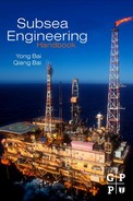
Corrosion is the degradation of a metal through its electrochemical reaction with the environment. A primary cause of corrosion is due to an effect known as galvanic corrosion. All metals have different natural electrical potentials. When two metals with different potentials are electrically connected to each other in an electrolyte (e.g., seawater), current will flow from the more active metal to the other, causing corrosion to occur. The less active metal is called the cathode, and the more active, the anode. In Figure 17-9, the more active metal, zinc, is the anode and the less active metal, steel, is the cathode. When the anode supplies current, it will gradually dissolve into ions in the electrolyte, and at the same time produce electrons, which the cathode will receive through the metallic connection with the anode. The result is that the cathode will be negatively polarized and, hence, protected against corrosion.
Figure 17-9 Galvanic Corrosion
17.3.1 Fundamentals of Cathodic Protection
Carbon steel structures exposed to natural waters generally corrode at an unacceptably high rate unless preventive measures are taken. Corrosion can be reduced or prevented by providing a direct current through the electrolyte to the structure. This method is called cathodic protection (CP), as showed in Figure 17-10.

Figure 17-10 Cathodic Protection of a Pipeline
The basic concept of cathodic protection is that the electrical potential of the subject metal is reduced below its corrosion potential, such that it will then be incapable of corroding. Cathodic protection results from cathodic polarization of a corroding metal surface to reduce the corrosion rate. The anodic and cathodic reactions for iron corroding in an aerated near neutral electrolyte are:
![]() (17-6)
(17-6)
![]() (17-7)
(17-7)
respectively. As a consequence of Equation (17-7), the pH of the seawater immediate close to a metal surface increases. This is beneficial because of the precipitation of solid compounds (calcareous deposits) by the reactions:
![]() (17-8)
(17-8)
and
![]() (17-9)
(17-9)
These deposits decrease the oxygen flux to the steel and, hence, the current necessary for cathodic protection. As a result, the service life of the entire cathodic protection system is extended.
Offshore pipelines can be protected as a cathode by achieving a potential of –0.80 VAg/AgCl or more negative, which is accepted as the protective potential (Eco ) for carbon steel and low-alloy steel in aerated water. Normally, it is the best if the potentials negative to –1.05 VAg/AgCl are avoided because these can cause a second cathodic reaction [7]:
![]() (17-10)
(17-10)
Cathodic protection systems are of two types: impressed current and galvanic anode. The latter has been widely used in the oil and gas industry for offshore platforms and marine pipeline in the past 40 years because of its reliability and relatively low cost of installation and operation. The effectiveness of cathodic protection systems allows carbon steel, which has little natural corrosion resistance, to be used in such corrosive environments as seawater, acid soils, and salt-laden concrete.
17.3.2 External Coatings
Oil and gas pipelines are protected by the combined use of coatings and cathodic protection. The coating systems are the primary barrier against corrosion and, therefore, are highly efficient at reducing the current demand for cathodic protection. However, they are not feasible for supplying sufficient electrical current to protect a bare pipeline. Cathodic protection prevents corrosion at areas of coating breakdown by supplying electrons.
Thick coatings are often applied to offshore pipelines to minimize the holidays and defects and to resist damage by handling during transport and installation. High electrical resistivity retained over long periods is a special requirement, because cathodic protection is universally used in conjunction with coatings for corrosion control. Coatings must have good adhesion to the pipe surface to resist disbondment and degradation by biological organisms, which abound in seawater. Pipe coating should be inspected both visually and by a holiday detector set at the proper voltage before the pipe is lowered into the water. Periodic inspection of the pipeline cathodic protection potential is used to identify the coating breakdown areas.
Coatings are selected based on the design temperature and cost. The principal coatings, in rough order of cost, are:
The most commonly used external coating for offshore pipeline is the fusion bonded epoxy (FBE) coating. FBE coatings are thin-film coatings, 0.5 to 0.6 mm thick. They consist of thermosetting powders that are applied to a white metal blast-cleaned surface by electrostatic spray. The powder will melt on the preheated pipe (around 230°C), flow, and subsequently cure to form thicknesses of between 250 and 650 μm. The FBE coating can be used in conjunction with a concrete weight coating. The other coating that can be used with a concrete coating is coal tar enamel, which is used with lower product temperatures.
The external coating can be dual layer or triple layer. Dual-layer FBE coatings are used when additional protection is required for the outer layer, such as protection from high temperatures or abrasion resistance. For deepwater flowlines the high temperature of the internal fluid dissipates rapidly, reaching ambient within a few miles. Therefore, the need for such coatings is limited for steel catenary riser (SCRS) at the touchdown area where abrasion is high and an additional coating with high abrasion resistance is used. Triple-layer PP coating consists of an epoxy or FBE, a thermoplastic adhesive coating, and a PP top coat. The PE and PP coatings are extruded coatings. These coatings are used for additional protection against corrosion and are commonly used for dynamic systems such as steel catenary risers and where the temperature of the internal fluid is high. These pipe coatings are also frequently used in reel pipelines. The field joint coating for the three-layer systems is more difficult to apply and takes a longer time. However, in Europe, PE and PP coatings are preferred because of their high dielectric strength, water tightness, thickness, and very low CP current requirement.
17.3.3 Cathodic Protection
Cathodic protection is a method by which corrosion of the parent metal is prevented. For offshore pipelines, the galvanic anode system is generally used. This section specifies parameters to be applied in the design of cathodic protection systems based on sacrificial anodes.
17.3.3.1 Design Life
The design life tr of the pipeline cathodic protection system is to be specified by the operator and shall cover the period from installation to the end of pipeline operation. It is normal practice to apply the same anode design life as for the offshore structures and submarine pipelines to be protected because maintenance and repair of CP systems are very costly.
17.3.3.2 Current Density
Current density refers to the cathodic protection current per unit of bare metal surface area of the pipeline. The initial and final current densities, ic (initial) and ic (final), give a measure of the anticipated cathodic current density demands to achieve cathodic protection of bare metal surfaces. They are used to calculate the initial and final current demands that determine the number and sizing of an anode. The initial design current density is necessarily higher than the average final current density because the calcareous deposits developed during the initial phase reduce the current demand. In the final phase, the developed marine growth and calcareous layers on the metal surface will reduce the current demand. However, the final design current density should take into account the additional current demand to repolarize the structure if such layers are damaged. The final design current density is lower than the initial density.
The average (or maintenance) design current density is a measure of the anticipated cathodic current density, once the cathodic protection system has attained its steady-state protection potential. This will simply imply a lower driving voltage, and the average design current density is therefore lower than both the initial and final design value.
Table 17-2 gives the recommended design current densities for the cathodic protection systems of nonburied offshore pipelines under various seawater conditions in different standards. For bare steel surfaces fully buried in sediments, a design current density of 20 mA/m2 is recommended irrespective of geographical location or depth.
Table 17-2. Summary of Recommended Design Current Densities for Bare Steel

17.3.3.3 Coating Breakdown Factor
The coating breakdown factor describes the extent of current density reduction due to the application of a coating. The value fc = 0 means the coating is 100% electrically insulating, whereas a value of fc = 1 implies that the coating cannot provide any protection.
The coating breakdown factor is a function of coating properties, operational parameters and time. The coating breakdown factor fc can be described as follows:
![]() (17-11)
(17-11)
where t is the coating lifetime, and k1 and k2 are constants that are dependent on the coating properties.
Four paint coating categories have been defined for practical use based on the coating properties in DNV [9]:
Category I: one layer of primer coat, about 50-μm nominal dry film thickness (DFT);
Category II: one layer of primer coat, plus minimum one layer of intermediate top coat, 150- to 250-μm nominal DFT;
Category III: one layer of primer coat, plus minimum two layers of intermediate/top coats, minimum 300-μm nominal DFT;
Category IV: one layer of primer coat, plus minimum three layers of intermediate top coats, minimum 450-μm nominal DFT.
The constants k1 and k2 used for calculating the coating breakdown factors are given in Table 17-3.
Table 17-3. Constants (k1 and k2) for Calculation of Paint Coating Breakdown Factors [10]

For cathodic protection design purposes, the average and final coating breakdown factors are calculated by introducing the design life tr :
![]() (17-12)
(17-12)
![]() (17-13)
(17-13)
17.3.3.4 Anode Material Performance
The performance of a sacrificial anode material is dependent on its actual chemical composition. The most commonly used anode materials are Al and Zn. Table 17-4 gives the electrochemical efficiency ϵ of anode materials applied in the determination of the required anode mass. The closed circuit anode potential used to calculate the anode current output should not exceed the values listed in the Table 17-5.
Table 17-4. Design Electrochemical Efficiency Values for Al- and Zn-Based Sacrificial Anode Materials [9]
| Anode Material Type | Electrochemical Efficiency (Ah/kg) |
| Al-based | 2000 (max 25°C) |
| Zn-based | 700 (max 50°C) |
Table 17-5. Design Closed-Circuit Anode Potentials for Al- and Zn-Based Sacrificial Anode Materials [9]
| Anode Material Type | Environment | Closed-Circuit Anode Potential (V rel. Ag/AgCl Seawater) |
| Al-based | Seawater | –1.05 |
| Sediments | –0.95 | |
| Zn-based | Seawater | –1.00 |
| Sediments | –0.95 |
17.3.3.5 Resistivity
The salinity and temperature of seawater have an influence on its resistivity. In the open sea, salinity does not vary significantly, so temperature becomes the main factor. The resistivities of 0.3 and 1.5 Ω·m are recommended to calculate anode resistance in seawater and marine sediments, respectively, when the temperature of surface water is between 7 and 12°C [9].
17.3.3.6 Anode Utilization Factor
The anode utilization factor indicates the fraction of anode material that is assumed to provide a cathodic protection current. Performance becomes unpredictable when the anode is consumed beyond a mass indicated by the utilization factor. The utilization factor of an anode is dependent on the detailed anode design, in particular, the dimensions and location of anode cores. Table 17-6 lists anode utilization factors for different types of anodes [9].
Table 17-6. Design Utilization Factors for Different Types of Anodes
| Anode Type | Anode Utilization Factor |
| Long 1, slender stand-off | 0.90 |
| Long 1, flush-mounted | 0.85 |
| Short 2, flush-mounted | 0.80 |
| Bracelet, half-shell type | 0.80 |
| Bracelet, segmented type | 0.75 |
17.3.4 Galvanic Anode System Design
17.3.4.1 Selection of Anode Type
Pipeline anodes are normally of the half-shell bracelet type (see Figure 17-11). The bracelets are clamped or welded to the pipe joints after application of the corrosion coating. Stranded connector cables are be used for clamped half-shell anodes. For the anodes mounted on the pipeline with concrete, measures should be taken to avoid the electrical contact between the anode and the concrete reinforcement.

Figure 17-11 Potential Profile of a Pipeline Protected by Bracelet Anodes
Normally, bracelet anodes are distributed at equal spacing along the pipeline. Adequate design calculations should demonstrate that anodes can provide the necessary current to the pipeline to meet the current density requirement for the entire design life. The potential of a pipeline should be polarized to –0.8 VAg/AgCl or more negative. Figure 17-11 shows the potential profile of a pipeline protected by galvanic bracelet anodes.
Because the installation expense is the main part of CP design, larger anode spacing can reduce the overall cost. However, the potential is not evenly distributed along the pipeline. The pipeline close to the anode has a more negative potential. The potential at the middle point on the pipeline between two anodes is more positive and must be polarized to –0.80 VAg/AgCl or more negative in order to achieve cathodic protection for the whole pipeline. Increased anode spacing results in a bigger mass per anode, causing an uneven potential distribution. The potential close to the anode could be polarized to be more negative than –1.05 VAg/AgCl, which should be avoided because of reaction 1.5. [10]Figure 17-12 illustrates the anticipated potential attenuation for situations using large anode spacing [10].

Figure 17-12 Pipeline Potential Profile for Large Anode Spacing
17.3.4.2 CP Design Practice
Offshore pipeline CP design includes the determination of the current demand Ic
, required anode mass M, and number and current output per anode Ia
. The current demand is a function of cathode surface area Ac
, a coating breakdown factor fc
, and current density ![]() , and can be expressed as follows [9]:
, and can be expressed as follows [9]:
![]() (17-14)
(17-14)
where ![]() depends on water depth, temperature, seawater versus mud exposure, and whether or not the mean or final life of the CP system is being evaluated. Current density
depends on water depth, temperature, seawater versus mud exposure, and whether or not the mean or final life of the CP system is being evaluated. Current density ![]() is normally in the range of 60 to 170 mA/m2[9]. Because the initial polarization period preceding steady-state conditions is normally quite short compared to the design life, the mean (time-averaged) design current density
is normally in the range of 60 to 170 mA/m2[9]. Because the initial polarization period preceding steady-state conditions is normally quite short compared to the design life, the mean (time-averaged) design current density ![]() comes very close to the steady-state current density. Therefore, it is used to calculate the minimum mass of anode material necessary to maintain cathodic protection throughout the design life. Correspondingly, M can be calculated as:
comes very close to the steady-state current density. Therefore, it is used to calculate the minimum mass of anode material necessary to maintain cathodic protection throughout the design life. Correspondingly, M can be calculated as:
![]() (17-15)
(17-15)
where u is a utilization factor, C is anode current capacity, and T is design life. The cathode potential is assumed to be spatially constant. Therefore, the current output per anode can be calculated by:
![]() (17-16)
(17-16)
where ![]() and
and ![]() are the closed-circuit potential of the pipe and anode, respectively, and
are the closed-circuit potential of the pipe and anode, respectively, and ![]() is the anode resistance.
is the anode resistance.
17.3.4.3 Anode Spacing Determination
Bethune and Hartt [11] have proposed a new attenuation equation to modify the existing design protocol interrelating the determination of the anode spacing Las , which can be expressed as:
![]() (17-17)
(17-17)
where,
This approach makes certain assumptions:
• Total circuit resistance is equal to anode resistance.
• All current enters the pipe at holidays in the coating (bare areas).
• The values of ![]() and
and ![]() are constant with both time and position. The ISO standards recommend that the distance between bracelet anodes not exceed 300 m [12].
are constant with both time and position. The ISO standards recommend that the distance between bracelet anodes not exceed 300 m [12].
17.3.4.4 Commonly Used Galvanic Anodes
The major types of galvanic anodes for offshore applications are slender stand-off, elongated flush mounted, and bracelet (Figure 17-13). The type of anode design to be applied is normally specified by the operator and should take into account various factors, such as anode utilization factor and current output, costs for manufacturing and installation, weight, and drag forces exerted by ocean current. The slender stand-off anode has the highest current output and utilization factor among these commonly used anodes.

Figure 17-13 Commonly Used Anodes
17.3.4.5 Pipeline CP System Retrofit
Cathodic protection system retrofits become necessary as pipeline systems age. An important aspect of such retrofitting is determination of when such action should take place. Assessment of cathodic protection systems is normally performed based on potential measurements. As galvanic anodes waste, their size decreases; this causes a resistance increase and a corresponding decrease in polarization. Models have been constructed for potential change that occurs for a pipeline protected by galvanic bracelet anodes as these deplete. Anode depletion is time dependent in the model.
Bracelet anodes have been used for cathodic protection of marine pipelines, especially during the “early period” (roughly 1964 to 1976), when many oil companies had construction activities in the Gulf of Mexico. According to recent survey data, many of these early anode systems have been depleted or are now being depleted. Retrofitting of old anode systems on pipelines installed in the 1960s and 1970s and even newer ones is required since these are still being used for oil transportation. Anodes can be designed as multiples or grouped together to form an anode array (anode sled) (see Figure 17-13). Anode arrays typically afford a good spread of protection on a marine structure. They are a good solution for retrofitting old cathodic protection systems.
17.4 Scales
Scales are deposits of many chemical compositions as a result of crystallization and precipitation of minerals from the produced water. The most common scale is formed from calcium carbonate. Scale is one of the most common and costly problems in the petroleum industry. This is because it interferes with the production of oil and gas, resulting in an additional cost for treatment, protection, and removal. Scale also results in a loss of profit that makes marginal wells uneconomical. Scale deposition can be minimized using scale inhibition chemicals. Anti-scale magnetic treatment methods have been studied for the past several decades as an alternative. Acid washing treatments are also used for removal of scale deposits in wells.
The solubility of individual scale species is dependent on the equilibrium constants of temperature and pressure; the activity coefficients, which are dependent on concentrations plus the temperature and pressure of each individual species; the bulk ionic strength of the solution; and the other ionic species present. Once the solution exceeds the saturation limit, scale will begin to precipitate.
17.4.1 Oil Field Scales
Oil field scales are generally inorganic salts such as carbonates and sulfates of the metals calcium, strontium, and barium. Oil field scales may also be the complex salts of iron such as sulfides, hydrous oxides, and carbonates. Oil field scales may form in one of following two ways:
• Due to the change of temperature or pressure for brine during production, the solubility of some of the inorganic constituents will decrease and result in the salts precipitating.
• When two incompatible waters (such as formation water rich in calcium, strontium, and barium and seawater rich in sulfate) are mixed. Scales formed under these conditions are generally sulfate scales.
Table 17-7 lists the most common water-formed scales in oil field waters. Table 17-8 lists the common causes for the formation of these deposits.
Table 17-7. Common Oil Well Scale Deposits—Solubility Factors [13]

Table 17-8. Common Oil Well Scale Deposits—Causes and Removal Chemicals [13]

17.4.1.1 Calcium Carbonate
Calcium carbonate, the most common scale in oil and gas field operations, occurs in every geographical area. Calcium carbonate precipitation occurs when calcium ion is combined with either carbonate or bicarbonate ions as follows,
![]() (17-18)
(17-18)
![]() (17-19)
(17-19)
The preceding equations show that the presence of CO2 will increase the solubility of CaCO3 in brine. Increasing CO2 also makes the water more acidic and decreases the pH. The calcium carbonate scaling usually occurs with a pressure drop, for example, at the wellbore. This reduces the partial pressure of CO2, thereby increasing the pH and decreasing the CaCO3 solubility. The solubility of calcium carbonate decreases with increasing temperature.
17.4.1.2 Calcium Sulfate
The precipitation of calcium sulfate is given by the reaction
![]() (17-20)
(17-20)
This scale may occur in different forms. Gypsum (CaSO4•2H2O) is the most common scale in oil field brines. It is associated with lower temperatures. Anhydrite (CaSO4) may occur at high temperatures. Theoretically, anhydrite would be expected to precipitate above 100°F in preference to gypsum because of its lower solubility. However, gypsum may be found at temperatures as high as 212°F. With the passage of time, gypsum will dehydrate to anhydrite.
A common mechanism for gypsum precipitation in the oil field is a reduction in pressure (e.g., at the production wellbore). The solubility increases with higher pressure because, when the scale is dissolved in water, the total volume of the system decreases.
17.4.1.3 Barium Sulfate
This scale is especially troublesome. It is extremely insoluble and almost impossible to remove chemically. Barium sulfate scaling is likely when both barium and sulfate are present, even in low concentrations.
![]() (17-21)
(17-21)
Barium sulfate scale is common in North Sea and GoM reservoirs. These fields often have barium in the original formation brine. Seawater injection (high sulfate concentration) for secondary oil recovery causes the scale problem. As the water flood matures and the seawater breaks through, these incompatible waters mix and a barium scale forms.
Generally, barium sulfate solubility increases with temperature and salinity. Similar to gypsum, BaSO4 solubility increases with an increase in total pressure and is largely unaffected by pH.
17.4.1.4 Strontium Sulfate
Strontium sulfate is similar to barium sulfate, except fortunately its solubility is much greater:
![]() (17-22)
(17-22)
Strontium sulfate solubility increases with salinity (up to 175,000 mg/L), temperature, and pressure. Again, pH has little effect. Pure strontium sulfate scale is rare except for some fields in the Middle East. SrSO4 deposits in producing wells where the strontium-rich formation water mixes with the sulfate-rich injected seawater.
17.4.2 Operational Problems Due to Scales
Scale deposits are not restricted to any particular location in the production system, although some locations are more important than others in terms of ease and cost of remedial treatment. The following are areas or events where scale formation is possible in production systems.
17.4.2.1 Drilling/Completing Wells
Scale can cause problems at this early stage if the drilling mud and/or completion brine is intrinsically incompatible with the formation water. For example, allowing a seawater-based mud to contact a formation water rich in barium and strontium ions would be undesirable, similar to allowing a high calcium brine to contact a formation water rich in bicarbonate.
17.4.2.2 Water Injection
Scale problems may be encountered when new water injection wells are commissioned if the injection water is intrinsically incompatible with the formation water. For example, seawater injection into an aquifer rich in strontium and/or barium ions could cause problems.
17.4.2.3 Water Production
As soon as a well begins to produce water, the risk of carbonate scale formation arises, assuming that the produced water has a tendency to precipitate carbonate scale. The severity of the problem will depend on the water chemistry, the rate of drawdown, and other factors such as pressure and temperature.
17.4.2.4 HP/HT Reservoirs
HP/HT reservoirs have some potentially unique scaling problems due to the following characteristics:
• Total dissolved solids (TDS) up to 300,000+ ppm;
Examples are the Eastern Trough Area Project and Elgin/Franklin reservoirs in the North Sea.
17.4.3 Scale Management Options
Scale can be managed in several ways:
• Prevent deposition by using scale inhibitors, etc.
• Allow scale to form, but periodically remove it.
• Use pretreatments that remove dissolved and suspended solids.
The typical way of preventing scale deposition in oil field production is through the use of scale inhibitors.
17.4.4 Scale Inhibitors
Scale inhibitors are chemicals that delay or prevent scale formation when added in small concentrations in water that would normally create scale deposits. Use of these chemicals is attractive because a very low dosage (several ppm) can be sufficient to prevent scale for extended periods of time for either surface or downhole treatments. The precise mechanism for scale inhibitors is not completely understood but is thought to be following:
• Scale inhibitors may adsorb onto the surface of the scale crystals just as they start to form. The inhibitors are large molecules that can envelop these microcrystals and hinder further growth. This is considered to be the primary mechanism.
• Many oil field chemicals are designed to operate at oil/water, liquid/gas, or solid/liquid interfaces. Since scale inhibitors have to act at the interface between solid scale and water, it is not surprising that their performance can be upset by the presence of other surface active chemicals that compete for the same interface. Before deployment, it is important to examine in laboratory tests the performance of a scale inhibitor in the presence of other oil field chemicals.
• Because these chemicals function by delaying the growth of scale crystals, the inhibitor must be present before the onset of precipitation. Suspended solids (nonadherent scales) are not acceptable. This suggests two basic rules in applying scale inhibitors: (1) The inhibitor must be added upstream of the problem area. (2) The inhibitor must be present in the scaling water on a continuous basis to stop the growth of each scale crystal as it precipitates.
17.4.4.1 Types of Scale Inhibitors
The common classes of scale inhibitors include:
17.4.4.2 Scale Inhibitor Selection
Following are criteria for the selection of scale inhibitor:
• Compatibility. The inhibitor must not interfere with other oil field chemicals nor be affected by other chemicals.
The detailed factors in the selection of scale inhibitor candidates for consideration in the performance tests include:
• Type of scale: The best scale-inhibitor chemistry based on the scale composition should be selected.
• Severity of scaling: Fewer products are effective at high scaling rates.
• Cost: Sometimes the cheaper products prove to be the most cost effective; sometimes the more expensive products do.
• Temperature: Higher temperatures and required longer life limit the types of chemistry that are suitable.
• pH: Most conventional scale inhibitors perform less effectively in a low-pH environment.
• Weather: The pour point should be considered if the inhibitor will be used in a cold-climate operation.
• Chemical compatibility: The scale inhibitor must be compatible with other treatment chemicals, such as oxygen scavengers, corrosion inhibitors, and biocides.
• Application technique: This is most important if the inhibitor is to be squeezed into the formation.
• Viscosity: This is important when considering long umbilical applications such as in remote subsea fields.
17.4.5 Scale Control in Subsea Field
17.4.5.1 Well
The production wells of a HP/HT reservoir in the G0M have a potential for barium sulfate scale deposition in the formation at the near-wellbore location or within the tubing. These deposits occur due to mixing of injection seawater and formation water. Sulfates in the injected seawater react with naturally occurring barium in the formation water to induce barium sulfate scale. Barium sulfate is not soluble in acid, so prevention rather than remediation by acid treatment is the key.
• If left untreated, barium sulfate scale is likely to form downhole and possibly in the formation after produced water breakthrough. These areas are not treatable with continuous downhole chemical injection. For this reason the treatment method will consist of periodic batch scale squeeze treatments into each production well. It is estimated that each production well will require treatment once per year.
• The barium sulfate scale control will depend on accurate well testing and analysis of produced fluids to detect whether there is adequate scale inhibitor in the near-wellbore area in order to prevent the formation of the scale. Well tests and fluid analysis will be required for each well at a frequency of once every 2 weeks.
17.4.5.2 Manifold and Pipeline
Both barium sulfate and calcium carbonate scale formation may occur at the manifold and in the pipelines due to comingling of incompatible produced waters from different reservoirs. Deposition in these areas will be controlled by scale inhibitor injection at the subsea tree. Scale inhibitor injection is required upstream of the subsea choke.
REFERENCES
1. de Waard C, Lotz U, Milliams DE. Predictive Model for CO2 Corrosion Engineering in Wet Natural Gas Pipelines. Corrosion. 1991;vol. 47(no12):976–985.
2. Norwegian Technology Standards Institution, CO2 Corrosion Rate Calculation Model, NORSOK Standard No. M-506, 2005.
3. Nyborg R. Controlling Internal Corrosion in Oil and Gas Pipelines. Oil and Gas Review 2005.
4. Dugstad A, Lunde L, Videm K. Parametric Study of CO2 Corrosion of Carbon Steel, Corrosion/94. Houston, TX: NACE International, paper no.14; 1994.
5. National Association of Corrosion Engineers. Metals for Sulfide Stress Cracking and Stress Corrosion Cracking Resistance in Soul Oilfield Environments. NACE MR. December 2003;0175.
6. www.corrosion-doctors.org/Inhibitors/lesson11.htm.
7. Jones DA. Principles and Prevention of Corrosion. first ed. New York: McMillan; 1992; pp. 437–445.
8. Sunde ED. Earth Conduction Effects in Transaction Systems. New York: Dover Publishing; 1968; pp. 70–73.
9. Det Norsk Veritas, Cathodic Protection Design, DNV RP B401, 1993.
10. Hartt WH, Zhang X, Chu W. Issues Associated with Expiration of Galvanic Anodes on Marine Structures, Paper 04093. Corrosion 2004.
11. K. Bethune, W.H. Hartt, A Novel Approach to Cathodic Protection Design for Marine Pipelines: Part II -Applicability of the Slope Parameter Method, presented at Corrosion, paper no.00674, 2000.
12. International Organization for Standardization, Pipeline Cathodic Protection-Part 2:Cathodic Protection of Offshore Pipelines, ISO/TC 67/SC 2 NP 14489, Washington, D.C, 1993.
13. DeepStar, Flow Assurance Design Guideline, 2001.